
EasyRig#
as_EasyRig: Advanced Biped Auto Rigger
Visit as_EasyRig: Advanced Biped Auto Rigger for more information.
as_EasyRig: Advanced Biped Auto Rigger
Visit as_EasyRig: Advanced Biped Auto Rigger for more information.
as_EasyRig: Advanced Biped Auto Rigger
Visit as_EasyRig: Advanced Biped Auto Rigger for more information.
EasyRig Features
:"Enhancing Character Rigging in Maya: Key Features of the EasyRig Module for Biped Characters":
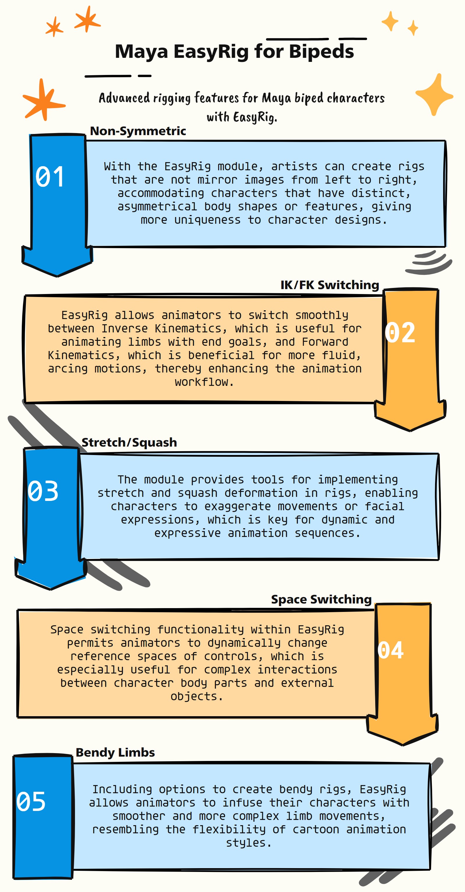
The EasyRig module, tailored for use in Autodesk Maya, is designed to facilitate the rigging of biped characters, incorporating a range of advanced features. Here are some of the key functionalities and uses of the EasyRig module:
Non-Symmetric Rigging: Supports creation of non-symmetric rigs, accommodating unique or asymmetrical body structures in characters.
IK/FK Switching: Includes tools for seamless switching between Inverse Kinematics and Forward Kinematics, essential for various animation techniques.
Stretch and Squash Capabilities: Offers functionalities for stretch and squash deformations, adding expressiveness and flexibility to animations.
Space Switching Functionality: Provides options for space switching, allowing for dynamic changes in the reference space of controls.
Bendy Setup Options: Features for creating bendy rigs, enabling smoother and more fluid movements in character limbs.
User-Friendly Rigging Process: Simplifies the rigging process, making it accessible for artists at different skill levels, while offering advanced options.
Customizable Rigging Options: Allows for extensive customization in rig setups to meet specific character and animation style requirements.
Seamless Integration with Maya Workflow: Designed for seamless integration with Maya’s environment, ensuring a smooth character setup and animation process.
Automated Rigging Solutions: Might include automated solutions to expedite the rigging process and ensure rig consistency across characters.
Advanced Deformation Controls: Likely offers advanced controls for deformations, enhancing the realism and quality of character movements.
- EasyRig.IKFKSwitch(self)#
[shArgs : None]
Purpose:
:: The IKFKSwitch function generates a custom switch control in Autodesk Maya using the curve command. This control typically represents an IK/FK switch in a character rig, allowing animators to switch between Inverse Kinematics and Forward Kinematics for limb control.
Code Examples:
>>> IKFKSwitch()
# This example demonstrates the creation of an IK/FK switch control, which is a curve with a specific shape and point positions.
graph TB Start[("fa:fa-play Start")] --> CreateSwitchCurve[("fas:fa-drafting-compass Create Switch Control Curve")] CreateSwitchCurve --> End[("fas:fa-stop End")] style Start fill:#00cc00,stroke:#000,stroke-width:3px style CreateSwitchCurve fill:#99ccff,stroke:#000,stroke-width:2px style End fill:#ff6666,stroke:#000,stroke-width:3px- Flow Chart Description:
The IKFKSwitch function’s flowchart illustrates this simple process:
The function begins with the creation of the switch control.
It uses the curve command in Maya to create a custom-shaped curve, which represents the IK/FK switch.
The control is created with specific point positions to form the desired shape.
The process ends after the control curve is successfully created.
- EasyRig.LFootControl(self)#
[shArgs : None]
Purpose:
:: The LFootControl function in Autodesk Maya creates an IK control for the left foot of a character. It utilizes MEL commands to generate a custom-shaped control curve and organizes it within a group for rigging purposes.
Code Examples:
>>> LFootControl()
# This example demonstrates the creation of a left foot IK control in a character rig.
graph TB Start[("fa:fa-play Start")] --> CreateFootCtrl[("fas:fa-drafting-compass Create Left Foot Control Curve")] CreateFootCtrl --> GroupFootCtrl[("fas:fa-object-group Group Left Foot Control")] GroupFootCtrl --> End[("fas:fa-stop End")] style Start fill:#00cc00,stroke:#000,stroke-width:3px style CreateFootCtrl fill:#99ccff,stroke:#000,stroke-width:2px style GroupFootCtrl fill:#99ccff,stroke:#000,stroke-width:2px style End fill:#ff6666,stroke:#000,stroke-width:3px- Flow Chart Description:
The LFootControl function’s flowchart illustrates the following process:
The function begins with creating the left foot IK control.
It uses MEL commands to create a curve that serves as the control for the left foot.
The control curve is then grouped to organize it within the rig, allowing for easier manipulation and animation.
The process ends after the control curve is grouped and set up for use in the rig.
- EasyRig.RFootControl(self)#
[shArgs : None]
Purpose:
:: The RFootControl function in Autodesk Maya creates an IK control for the right foot of a character. This function mirrors the approach used for the left foot, generating a similar control curve, flipping it for the right side, and organizing it within a group for rigging.
Code Examples:
>>> RFootControl()
# This example demonstrates the creation of a right foot IK control in a character rig.
graph TB Start[("fa:fa-play Start")] --> CreateFootCtrl[("fas:fa-drafting-compass Create Right Foot Control Curve")] CreateFootCtrl --> GroupFootCtrl[("fas:fa-object-group Group Right Foot Control")] GroupFootCtrl --> MirrorFootCtrl[("fas:fa-arrows-alt-h Mirror Control for Right Foot")] MirrorFootCtrl --> ApplyTransforms[("fas:fa-sync-alt Apply Transforms to Group")] ApplyTransforms --> End[("fas:fa-stop End")] style Start fill:#00cc00,stroke:#000,stroke-width:3px style CreateFootCtrl fill:#99ccff,stroke:#000,stroke-width:2px style GroupFootCtrl fill:#99ccff,stroke:#000,stroke-width:2px style MirrorFootCtrl fill:#99ccff,stroke:#000,stroke-width:2px style ApplyTransforms fill:#99ccff,stroke:#000,stroke-width:2px style End fill:#ff6666,stroke:#000,stroke-width:3px- Flow Chart Description:
The RFootControl function’s flowchart illustrates the following process:
Starts by creating a control curve for the right foot using MEL commands.
Groups the created control to manage it efficiently within the rig.
Mirrors the control to properly align it for the right foot.
Applies transformations to the group to finalize the control’s position and orientation.
Completes the process, setting up the right foot control for use in the character rig.
- EasyRig.__confirmAction(self, action)#
- EasyRig.__init__(self)#
To Create auto biped rig based on curves and to Create cluster based controls
- EasyRig._compileEasyRig(self, userFolder='$_Free_EasyRig_v1.0')#
- EasyRig._isInTime(self, startDate=[2017, 1, 1], endDate=[2018, 1, 1], onlineTime=1, showDaysLeft=1, bufferTime=1)#
- EasyRig._mayaVer(self)#
- EasyRig.add_ExJnt(self, baseJnt, exJntName, numJnts=2, movAmount=0.4)#
[shArgs : None]
Purpose:
:: The add_ExJnt function is a utility in Autodesk Maya for creating extra joints in a joint hierarchy. It allows the user to specify the base joint, name for the extra joint, the number of joints to be added, and the relative movement amount for positioning the extra joints.
Code Examples:
>>> add_ExJnt("joint1", "extraJoint", numJnts=2, movAmount=0.4)
# This example shows the usage of add_ExJnt function to add an extra joint to a joint named 'joint1', naming the extra joint 'extraJoint', creating 2 joints and moving the second one by 0.4 times the translation value of the next base joint.
graph TB Start[("fa:fa-play Start")] --> ClearSelection[("fas:fa-times-circle Clear Selection")] ClearSelection --> CreateJoint[("fas:fa-plus-circle Create Joint")] CreateJoint --> SnapToBase[("fas:fa-compress-alt Snap to Base Joint")] SnapToBase --> ParentToBase[("fas:fa-sitemap Parent to Base Joint")] ParentToBase --> GetChildJoint[("fas:fa-sitemap Get Child Joint")] GetChildJoint --> CheckNumJnts{{"/fas:fa-question Check Number of Joints"}} CheckNumJnts --"If numJnts is 2" --> InsertSecondJoint[("fas:fa-sitemap Insert Second Joint")] InsertSecondJoint --> RenameSecondJoint[("fas:fa-text-height Rename Second Joint")] RenameSecondJoint --> GetTranslation[("fas:fa-arrows-alt Get Translation")] GetTranslation --> MoveSecondJoint[("fas:fa-arrows-alt Move Second Joint")] MoveSecondJoint --> End[("fas:fa-stop End")] CheckNumJnts --"If numJnts is not 2" --> End style Start fill:#00cc00,stroke:#000,stroke-width:3px style ClearSelection fill:#99ccff,stroke:#000,stroke-width:2px style CreateJoint fill:#99ccff,stroke:#000,stroke-width:2px style SnapToBase fill:#99ccff,stroke:#000,stroke-width:2px style ParentToBase fill:#99ccff,stroke:#000,stroke-width:2px style GetChildJoint fill:#99ccff,stroke:#000,stroke-width:2px style CheckNumJnts fill:#ffcc00,stroke:#000,stroke-width:2px style InsertSecondJoint fill:#99ccff,stroke:#000,stroke-width:2px style RenameSecondJoint fill:#99ccff,stroke:#000,stroke-width:2px style GetTranslation fill:#99ccff,stroke:#000,stroke-width:2px style MoveSecondJoint fill:#99ccff,stroke:#000,stroke-width:2px style End fill:#ff6666,stroke:#000,stroke-width:3px- Flow Chart Description:
The add_ExJnt function’s flowchart demonstrates the following sequence:
The function begins by clearing the current selection in the Maya scene.
A new joint is created and named according to the specified exJntName.
The newly created joint is positioned and oriented to match the specified base joint.
The joint is then parented to the base joint.
The function identifies the next base joint as a child of the specified base joint.
If the number of joints to add (numJnts) is 2, a second extra joint is inserted and renamed accordingly.
The translation value of the next base joint is obtained.
The second extra joint is moved a specified amount (movAmount) relative to the translation value.
The process completes if numJnts is not 2 or after moving the second joint.
- EasyRig.add_ExJnt01(self, baseJnt, exJntName, numJnts=2, movAmount=0.25)#
[shArgs : None]
Purpose:
:: The add_ExJnt01 function is designed to add an extra joint to an existing joint chain in Autodesk Maya. :: It allows customization of the extra joint’s name, the number of joints to add, and their relative position.
Code Examples:
>>> add_ExJnt01("joint1", "extraJoint", numJnts=2, movAmount=0.25)
# This example shows the usage of add_ExJnt01 function to add an extra joint to a joint named 'joint1', naming the extra joint 'extraJoint', creating 2 joints and moving the second one by 0.25 times the translation value of the next base joint.
graph TB Start[("fa:fa-play Start")] --> CreateJoint[("fas:fa-plus-circle Create Joint")] CreateJoint --> GetChildJoint[("fas:fa-sitemap Get Child Joint")] GetChildJoint --> InsertJoint[("fas:fa-sitemap Insert Joint")] InsertJoint --> RenameExJnt[("fas:fa-text-height Rename Extra Joint")] RenameExJnt --> CheckNumJnts{{"/fas:fa-question Check Number of Joints"}} CheckNumJnts --"If numJnts is 2" --> InsertSecondJoint[("fas:fa-sitemap Insert Second Joint")] InsertSecondJoint --> RenameSecondJoint[("fas:fa-text-height Rename Second Joint")] RenameSecondJoint --> GetTranslation[("fas:fa-arrows-alt Get Translation")] GetTranslation --> MoveSecondJoint[("fas:fa-arrows-alt Move Second Joint")] MoveSecondJoint --> End[("fas:fa-stop End")] CheckNumJnts --"If numJnts is not 2" --> End style Start fill:#00cc00,stroke:#000,stroke-width:3px style CreateJoint fill:#99ccff,stroke:#000,stroke-width:2px style GetChildJoint fill:#99ccff,stroke:#000,stroke-width:2px style InsertJoint fill:#99ccff,stroke:#000,stroke-width:2px style RenameExJnt fill:#99ccff,stroke:#000,stroke-width:2px style CheckNumJnts fill:#ffcc00,stroke:#000,stroke-width:2px style InsertSecondJoint fill:#99ccff,stroke:#000,stroke-width:2px style RenameSecondJoint fill:#99ccff,stroke:#000,stroke-width:2px style GetTranslation fill:#99ccff,stroke:#000,stroke-width:2px style MoveSecondJoint fill:#99ccff,stroke:#000,stroke-width:2px style End fill:#ff6666,stroke:#000,stroke-width:3px- Flow Chart Description:
The add_ExJnt01 function’s flowchart illustrates the following process:
The function starts by creating a new joint in the Maya scene.
It then identifies the next base joint as a child of the specified base joint.
An extra joint (exJnt) is inserted into the base joint.
The extra joint is renamed to the specified exJntName.
The function checks if the number of joints to add (numJnts) is 2.
If yes, a second extra joint (nxtExJnt) is inserted and renamed accordingly.
The translation value of the next base joint is retrieved.
The second extra joint is then moved a specified amount (movAmount) relative to the translation value.
The process ends if numJnts is not 2 or after moving the second joint.
- EasyRig.add_JntAttrs_AHSS(self)#
[shArgs : None]
Purpose:
:: The add_JntAttrs_AHSS function is designed to automate the process of adding custom attributes to joints in Autodesk Maya. These attributes facilitate advanced controls in rigging, particularly for skinning and deformation. The function checks if joints are given or selects skin joints from a skinned mesh and adds attributes like baseBlend, tailBlend, and moreVolume, among others, to each joint.
Code Examples:
>>> add_JntAttrs_AHSS()
# This example shows the usage of add_JntAttrs_AHSS function to add custom attributes to selected joints or joints associated with a selected skinned mesh.
graph TD Start[("fa:fa-play Start")] --> CheckSelection{{"fas:fa-question-circle Check If Joints or Skinned Mesh Selected"}} CheckSelection --"Joints Selected" --> SetJntsGivenTrue[("fas:fa-check Set JntsGiven to True")] SetJntsGivenTrue --> CreateJntList[("fas:fa-sitemap Create Joint List from Selection")] CheckSelection --"Skinned Mesh Selected" --> GetSkinMeshName[("fas:fa-code Get Skin Mesh Name")] GetSkinMeshName --> SetJntsGivenFalse[("fas:fa-times-circle Set JntsGiven to False")] SetJntsGivenFalse --> GetSkinJnts[("fas:fa-sitemap Get Skinned Joints")] GetSkinJnts --> CreateJntList CheckSelection --"Neither Joints nor Skinned Mesh Selected" --> DisplayError[("fas:fa-exclamation-triangle Display Error Message")] CreateJntList --> ForEachJoint[("fa:fa-repeat For Each Joint in Joint List")] ForEachJoint --> AddCustomAttrs[("fas:fa-plus-circle Add Custom Attributes")] AddCustomAttrs --> End[("fas:fa-stop End")] style Start fill:#00cc00,stroke:#000,stroke-width:3px style CheckSelection fill:#ffcc00,stroke:#000,stroke-width:2px style SetJntsGivenTrue fill:#99ccff,stroke:#000,stroke-width:2px style CreateJntList fill:#99ccff,stroke:#000,stroke-width:2px style GetSkinMeshName fill:#99ccff,stroke:#000,stroke-width:2px style SetJntsGivenFalse fill:#99ccff,stroke:#000,stroke-width:2px style GetSkinJnts fill:#99ccff,stroke:#000,stroke-width:2px style DisplayError fill:#ff6666,stroke:#000,stroke-width:2px style ForEachJoint fill:#ffcc00,stroke:#000,stroke-width:2px style AddCustomAttrs fill:#99ccff,stroke:#000,stroke-width:2px style End fill:#ff6666,stroke:#000,stroke-width:3px- Flow Chart Description:
The add_JntAttrs_AHSS function’s flowchart demonstrates the following sequence:
The function starts by checking if any joints or skinned mesh are selected.
If joints are selected, it sets the flag ‘jntsGiven’ to True and creates a list of selected joints.
If a skinned mesh is selected, it retrieves the skin mesh’s name, sets ‘jntsGiven’ to False, and gets the joints affected by the skin mesh.
An error message is displayed if neither joints nor skinned mesh are selected.
The function then iterates over each joint in the list.
Custom attributes are added to each joint, including baseBlend, tailBlend, and moreVolume.
The process completes after adding attributes to all joints in the list.
- EasyRig.add_Selection(self, textFldName)#
[shArgs : tf=textFld, ms=multiSelect]
Purpose:
:: Adds the name of the selected Maya object(s) to a specified UI text field.
Useful for quickly transferring selected object names into user interfaces or scripts within Maya.
Can handle multiple selections, appending each selected object’s name to the text field.
Streamlines workflows involving the selection and naming of objects in Maya.
- Parameters:
textFld – <str> # The name of the text field where the object’s name will be inputted.
multiSelect – <bool> # Indicates whether multiple object names should be concatenated and added to the text field.
- Returns:
None # This function does not return any value but updates the UI text field with the selected object name(s).
Code Examples:
>>> add_Selection(textFld='objectNameField', multiSelect=True)
# Adds names of all selected objects to 'objectNameField'.

>>> add_Selection(textFld='singleObjectNameField', multiSelect=False)
# Adds the name of the first selected object to 'singleObjectNameField'.
Usage:
obj10           # Adds 'obj10' While pressing Enter.. <== button
box25           # Adds 'box25' While pressing Enter.. <== button
graph TB Start[("fa:fa-play Start")] --> CheckSelection{"/fas:fa-mouse-pointer Check Object Selection"} CheckSelection --"If Objects are Selected"--> DetermineSelectionType{"/fas:fa-list-ul Determine Selection Type"} CheckSelection --"If No Objects are Selected"--> ClearField["/fas:fa-eraser Clear Field"] DetermineSelectionType --"If Multi-Select is True"--> ConcatenateNames["/fas:fa-stream Concatenate Object Names"] DetermineSelectionType --"If Multi-Select is False"--> AddSingleName["/fas:fa-plus-circle Add Single Object Name"] ConcatenateNames --> UpdateField["/fas:fa-pencil-alt Update Field"] AddSingleName --> UpdateField ClearField --> End["/fas:fa-stop End"] UpdateField --> End style Start fill:#00cc00,stroke:#000,stroke-width:3px style CheckSelection fill:#ffcc99,stroke:#000,stroke-width:2px style DetermineSelectionType fill:#99ccff,stroke:#000,stroke-width:2px style ConcatenateNames fill:#ccffcc,stroke:#000,stroke-width:2px style AddSingleName fill:#cc99ff,stroke:#000,stroke-width:2px style UpdateField fill:#ff9999,stroke:#000,stroke-width:2px style ClearField fill:#99ff99,stroke:#000,stroke-width:2px style End fill:#ff6666,stroke:#000,stroke-width:3px- Flow Chart Description:
This flowchart illustrates the add_Selection function:
The process starts by checking if objects are selected in Maya.
If objects are selected, it determines if multiple selections are allowed.
If multiple selections are allowed, it concatenates the names of all selected objects.
If only a single selection is allowed, it adds the name of the first selected object.
The selected object names are then added to the specified text field.
If no objects are selected, the function clears the specified text field.
The process ends after updating or clearing the text field.
- EasyRig.apply(self)#
[shArgs : None]
Purpose:
:: The apply function is designed to automate the process of applying parent constraints from skin joints to skeleton geometry within Autodesk Maya. It’s particularly useful for rigging, ensuring that geometry follows the respective joints’ movements.
Code Example:
>>> apply()
# This example applies parent constraints from nearest joints to the selected skeleton geometry.
graph TB Start[("fa:fa-play Start")] --> CheckSelection{{"/fas:fa-check-circle Check Selection"}} CheckSelection --"Nothing Selected" --> ShowError[("/fas:fa-exclamation-triangle Show Error")] CheckSelection --"Skeleton Selected" --> GetSkeletonList[("fas:fa-list Get Skeleton List")] GetSkeletonList --> GetJointList[("fas:fa-bone Get Joint List")] GetJointList --> ApplyConstraints[("fas:fa-link Apply Constraints")] ShowError --> End[("fas:fa-stop End")] ApplyConstraints --> End style Start fill:#00cc00,stroke:#000,stroke-width:3px style CheckSelection fill:#ffcc00,stroke:#000,stroke-width:2px style ShowError fill:#ff9999,stroke:#000,stroke-width:2px style GetSkeletonList fill:#99ccff,stroke:#000,stroke-width:2px style GetJointList fill:#cc99ff,stroke:#000,stroke-width:2px style ApplyConstraints fill:#99ff99,stroke:#000,stroke-width:2px style End fill:#ff6666,stroke:#000,stroke-width:3px- Flow Chart Description:
The apply function’s flowchart depicts the following steps:
The process begins by checking if any object is selected in the Maya scene.
If no selection is found, it displays an error message.
If a skeleton (or top group of skeleton geometry) is selected, it collects a list of all geometry within the skeleton’s hierarchy.
It then gathers a list of all joints within the scene.
The function applies parent constraints from the nearest joints in the list to each piece of skeleton geometry.
The process ends after successfully applying the constraints.
- EasyRig.applyCharPrefix(self)#
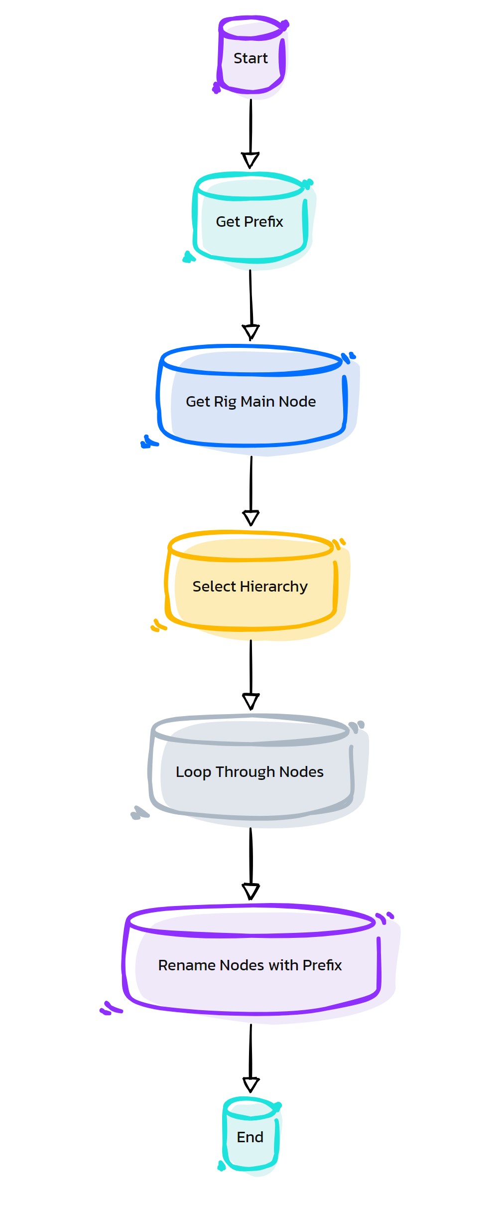
Purpose:
:: The applyCharPrefix function renames all nodes in a rig hierarchy by adding a specific prefix. :: This helps in organizing and identifying nodes related to a particular character or element in complex scenes.
Code Examples:
>>> applyCharPrefix()
# This example demonstrates the use of applyCharPrefix function to rename all nodes in a rig hierarchy with a specific prefix.
graph TB Start[("fa:fa-play Start")] --> GetPrefix[("fas:fa-text-height Get Prefix")] GetPrefix --> GetRigMain[("fas:fa-sitemap Get Rig Main Node")] GetRigMain --> SelectHierarchy[("fas:fa-code-branch Select Hierarchy")] SelectHierarchy --> LoopNodes[("fas:fa-repeat Loop Through Nodes")] LoopNodes --> RenameNodes[("fas:fa-i-cursor Rename Nodes with Prefix")] RenameNodes --> End[("fas:fa-stop End")] style Start fill:#00cc00,stroke:#000,stroke-width:3px style GetPrefix fill:#99ccff,stroke:#000,stroke-width:2px style GetRigMain fill:#99ccff,stroke:#000,stroke-width:2px style SelectHierarchy fill:#99ccff,stroke:#000,stroke-width:2px style LoopNodes fill:#99ccff,stroke:#000,stroke-width:2px style RenameNodes fill:#99ccff,stroke:#000,stroke-width:2px style End fill:#ff6666,stroke:#000,stroke-width:3px- Flow Chart Description:
The applyCharPrefix function flowchart illustrates the following process:
The function starts by retrieving the prefix label specified in the Maya text field.
It then identifies the main rig node, typically named ‘Rig_Main’, in the Maya scene.
The hierarchy of the rigMain node is selected to include all child nodes for renaming.
The function loops through each node in the selected hierarchy.
Each node is renamed by adding the specified prefix to its original name, ensuring consistent naming across the rig hierarchy.
The process ends once all nodes in the rig hierarchy have been renamed with the prefix, helping in better organization and management of rig components.
- EasyRig.as_AboutEasyRig(self)#
[shArgs : None]
Purpose:
:: The as_AboutEasyRig function creates a window in Autodesk Maya displaying credits and information about the as_EasyRig tool. This is often used for informational or credit purposes in software development.
Code Example:
>>> as_AboutEasyRig()
# Displays a window with credits and information about as_EasyRig.
graph TB Start[("fa:fa-play Start")] --> CheckWindow[("/fas:fa-window-maximize Check if Window Exists")] CheckWindow --"If window exists" --> DeleteWindow[("/fas:fa-window-close Delete Existing Window")] CheckWindow --"If window does not exist" --> DefineWindowStyle[("/fas:fa-cogs Define Window Style")] DeleteWindow --> DefineWindowStyle DefineWindowStyle --> CreateWindow[("/fas:fa-window-maximize Create Window")] CreateWindow --> AddContent[("/fas:fa-text-width Add Content")] AddContent --> ShowWindow[("/fas:fa-eye Show Window")] ShowWindow --> WaitForUser[("/fas:fa-clock Wait for User Interaction")] WaitForUser --"After 3 seconds" --> AutoClose[("/fas:fa-times-circle Auto Close Window")] AutoClose --> End[("fas:fa-stop End")] style Start fill:#00cc00,stroke:#000,stroke-width:3px style End fill:#ff6666,stroke:#000,stroke-width:3px- Flow Chart Description:
This flowchart illustrates the as_AboutEasyRig function:
The function begins by checking if the “EasyRigCreditsWin” window already exists. If it does, the existing window is deleted.
Next, it defines the window’s style based on the Maya version.
A new window is created with the title “as_EasyRig_v1.0 Credits..”.
Content including author information, visit links, contact details, and copyright notices are added to the window.
The window is then displayed to the user.
The function waits for user interaction or automatically closes the window after 3 seconds.
- EasyRig.as_ActivateSetPose(self, expEditor=False)#
[shArgs : None]
Purpose:
:: The as_ActivateSetPose function in Autodesk Maya creates a script that resets the pose of selected controls to their default state. It can be particularly useful for animators to quickly revert a character to a neutral pose.
Code Example:
>>> as_ActivateSetPose(expEditor=False)
# This example will execute the function to generate a script that resets selected controls to a default pose.
graph TB Start[("fa:fa-play Start")] --> SetGlobalVariable["/fas:fa-cog Set Global Variable"] SetGlobalVariable --> DeleteExistingScript["/fas:fa-trash-alt Delete Existing Script"] DeleteExistingScript --> SelectCtrls["/fas:fa-mouse-pointer Select Controls"] SelectCtrls --"If controls are selected" --> GenerateScript["/fas:fa-code Generate Script"] SelectCtrls --"If no controls selected" --> DisplayWarning["/fas:fa-exclamation-triangle Display Warning"] GenerateScript --> CreateScriptNode["/fas:fa-file-code Create Script Node"] CreateScriptNode --> ClearSelection["/fas:fa-times-circle Clear Selection"] DisplayWarning --> ClearSelection ClearSelection --> OpenExpEditor["/fas:fa-edit Open Expression Editor"] OpenExpEditor --> End[("fas:fa-stop End")] style Start fill:#00cc00,stroke:#000,stroke-width:3px style SetGlobalVariable fill:#ff9999,stroke:#000,stroke-width:2px style DeleteExistingScript fill:#99ccff,stroke:#000,stroke-width:2px style SelectCtrls fill:#ffcc00,stroke:#000,stroke-width:2px style GenerateScript fill:#99ff99,stroke:#000,stroke-width:2px style CreateScriptNode fill:#ff9999,stroke:#000,stroke-width:2px style ClearSelection fill:#99ccff,stroke:#000,stroke-width:2px style DisplayWarning fill:#ffcc00,stroke:#000,stroke-width:2px style OpenExpEditor fill:#99ff99,stroke:#000,stroke-width:2px style End fill:#ff6666,stroke:#000,stroke-width:3px- Flow Chart Description:
The as_ActivateSetPose function operates through these steps:
Sets a global variable based on the label from a text field.
Attempts to delete an existing script with the same label if it exists.
Selects controls in the scene based on a naming pattern.
Generates a script command to reset the attributes of selected controls.
Creates a new script node with the generated command.
Clears the current selection in the scene.
Optionally opens the Expression Editor if expEditor is True.
The process ends after these operations are completed.
- EasyRig.as_BasicSetup(self)#
[shArgs : None]
Purpose:
:: The as_BasicSetup function is designed to initialize a basic 3D rigging setup in Autodesk Maya. :: It involves creating various control curves, handle controls, and rigging components to set up a character or object for animation.
Code Examples:
>>> as_BasicSetup()
# This example demonstrates how the as_BasicSetup function is used to initialize a basic rigging setup in Maya.
graph TB Start[("fa:fa-play Start")] --> DeleteExistingSetup[("fas:fa-trash-alt Delete Existing Setup")] DeleteExistingSetup --> GlobalVariables[("fas:fa-globe-americas Set Global Variables")] GlobalVariables --> GenerateCurves[("fas:fa-bezier-curve Generate Curves")] GenerateCurves --> CheckAsymmetry[("fas:fa-balance-scale Check Asymmetry")] CheckAsymmetry --"If Asymmetry Enabled" --> GenerateMirrorCurves[("fas:fa-clone Generate Mirror Curves")] CheckAsymmetry --"If Asymmetry Disabled" --> SpineSetup[("fas:fa-spine Spine Setup")] GenerateMirrorCurves --> SpineSetup SpineSetup --> NeckSetup[("fas:fa-necktie Neck Setup")] NeckSetup --> ParentCurves[("fas:fa-sitemap Parent Curves")] ParentCurves --> CreateHandleControls[("fas:fa-hand-paper Create Handle Controls")] CreateHandleControls --> ConfigureControls[("fas:fa-wrench Configure Controls")] ConfigureControls --> FinalizeSetup[("fas:fa-check-circle Finalize Setup")] FinalizeSetup --> End[("fas:fa-stop End")] style Start fill:#00cc00,stroke:#000,stroke-width:3px style DeleteExistingSetup fill:#99ccff,stroke:#000,stroke-width:2px style GlobalVariables fill:#99ccff,stroke:#000,stroke-width:2px style GenerateCurves fill:#99ccff,stroke:#000,stroke-width:2px style CheckAsymmetry fill:#ffcc00,stroke:#000,stroke-width:2px style GenerateMirrorCurves fill:#99ccff,stroke:#000,stroke-width:2px style SpineSetup fill:#99ccff,stroke:#000,stroke-width:2px style NeckSetup fill:#99ccff,stroke:#000,stroke-width:2px style ParentCurves fill:#99ccff,stroke:#000,stroke-width:2px style CreateHandleControls fill:#99ccff,stroke:#000,stroke-width:2px style ConfigureControls fill:#99ccff,stroke:#000,stroke-width:2px style FinalizeSetup fill:#99ccff,stroke:#000,stroke-width:2px style End fill:#ff6666,stroke:#000,stroke-width:3px- Flow Chart Description:
The as_BasicSetup function flowchart illustrates the following process:
The function starts by deleting any existing setup if present.
It then initializes global variables required for the rigging process.
The function generates various control curves for different parts of the character or object.
It checks if asymmetry is enabled and accordingly generates mirror curves for the opposite side.
The spine and neck setup are executed, involving the creation of joints and controls for these areas.
The generated curves are parented to establish a hierarchy.
Handle controls are created for all curve vertices, allowing for detailed manipulation of the rig.
These controls are then configured for their specific purposes and attributes.
The setup is finalized, integrating all components into a functional rig.
The process ends with the basic rigging setup ready for animation.
- EasyRig.as_BendySetup(self, baseJnt, bendyCount=4, elbowBendy=False, deleteUnwanted='hands', globalCtrl='Placement01_Ctrl', bendySwitch=None)#
[shArgs : baseJnt, bendyCount, elbowBendy, deleteUnwanted, globalCtrl, bendySwitch]
Purpose:
:: The as_BendySetup function sets up a dynamic bendy system for character rigging in Autodesk Maya. It generates bendy joints, controls, and IK handles for smoother deformations in character limbs.
Code Example:
>>> as_BendySetup('L_Shoulder_Jnt', bendyCount=4, elbowBendy=True, deleteUnwanted='hands', globalCtrl='Placement01_Ctrl')
# This example creates a bendy setup for the left shoulder joint, with 4 bendy divisions, elbow bendy, hand deletion, and global control as 'Placement01_Ctrl'.
graph TB Start[("fa:fa-play Start")] --> ProcessInputs["/fas:fa-cogs Process Inputs"] ProcessInputs --> DeleteUnwanted{"/fas:fa-trash-alt Delete Unwanted"} DeleteUnwanted --"If hands" --> DeleteHands["/fas:fa-hand-paper Delete Hands"] DeleteUnwanted --"If legs" --> DeleteLegs["/fas:fa-walking Delete Legs"] DeleteHands --> CreateGroups["/fas:fa-layer-group Create Groups"] DeleteLegs --> CreateGroups DeleteUnwanted --"None" --> CreateGroups CreateGroups --> CreateBendyCurve["/fas:fa-curve Create Bendy Curve"] CreateBendyCurve --> CreateBendyJoints["/fas:fa-sitemap Create Bendy Joints"] CreateBendyJoints --> PlaceLocators["/fas:fa-map-marker-alt Place Locators"] PlaceLocators --> CreateBendyControls["/fas:fa-sliders-h Create Bendy Controls"] CreateBendyControls --> AddTwistJoints["/fas:fa-sync-alt Add Twist Joints"] AddTwistJoints --> ConfigureTangentConstraint["/fas:fa-link Configure Tangent Constraint"] ConfigureTangentConstraint --> SetupTwistPercent["/fas:fa-percent Setup Twist Percent"] SetupTwistPercent --> FinalizeSetup["/fas:fa-check-circle Finalize Setup"] FinalizeSetup --> End[("fas:fa-stop End")] style Start fill:#00cc00,stroke:#000,stroke-width:3px style ProcessInputs fill:#ffcc00,stroke:#000,stroke-width:2px style DeleteUnwanted fill:#ff9999,stroke:#000,stroke-width:2px style DeleteHands fill:#99ccff,stroke:#000,stroke-width:2px style DeleteLegs fill:#cc99ff,stroke:#000,stroke-width:2px style CreateGroups fill:#99ff99,stroke:#000,stroke-width:2px style CreateBendyCurve fill:#ff6666,stroke:#000,stroke-width:2px style CreateBendyJoints fill:#66ccff,stroke:#000,stroke-width:2px style PlaceLocators fill:#ccccff,stroke:#000,stroke-width:2px style CreateBendyControls fill:#ffcc66,stroke:#000,stroke-width:2px style AddTwistJoints fill:#66ffcc,stroke:#000,stroke-width:2px style ConfigureTangentConstraint fill:#ccff66,stroke:#000,stroke-width:2px style SetupTwistPercent fill:#ff99cc,stroke:#000,stroke-width:2px style FinalizeSetup fill:#99cccc,stroke:#000,stroke-width:2px style End fill:#ff6666,stroke:#000,stroke-width:3px- Flow Chart Description:
The as_BendySetup function carries out these steps:
Process Inputs: Prepares necessary inputs like side position and joint axis.
Delete Unwanted: Removes unwanted joints based on the specified option (hands or legs).
Create Groups: Sets up groups for bendy systems, twist, and curves.
Create Bendy Curve: Generates a curve along the joint chain for the bendy system.
Create Bendy Joints: Creates bendy joints based on the provided bendy count.
Place Locators: Positions start, middle, and end locators for the bendy curve.
Create Bendy Controls: Adds controls for manipulating the bendy curve.
Add Twist Joints: Implements joints for twist deformation control.
Configure Tangent Constraint: Sets up constraints for aligning bendy joints with the curve.
Setup Twist Percent: Configures the twist percentage for each bendy joint.
Finalize Setup: Completes the setup by hiding unnecessary elements and creating switch attributes if needed.
- EasyRig.as_BendySetup_Hands(self, bendyCount=4)#
[shArgs : bendyCount]
Purpose:
:: The as_BendySetup_Hands function is designed to automate the bendy setup for both arms (including the shoulders and elbows) of a character rig in Autodesk Maya. It calls the as_BendySetup function for each joint in the arm, simplifying the process of creating a bendy rig for the hands.
Code Example:
>>> as_BendySetup_Hands(bendyCount=4)
# This example creates a bendy setup for both arms with 4 bendy divisions.
graph TB Start[("fa:fa-play Start")] --> SetGlobalCtrl["/fas:fa-cogs Set Global Control"] SetGlobalCtrl --> CreateL_ElbowBendy["/fas:fa-arrow-alt-circle-right Create L_Elbow Bendy"] CreateL_ElbowBendy --> CreateL_ShoulderBendy["/fas:fa-arrow-alt-circle-right Create L_Shoulder Bendy"] CreateL_ShoulderBendy --> CreateR_ElbowBendy["/fas:fa-arrow-alt-circle-right Create R_Elbow Bendy"] CreateR_ElbowBendy --> CreateR_ShoulderBendy["/fas:fa-arrow-alt-circle-right Create R_Shoulder Bendy"] CreateR_ShoulderBendy --> End[("fas:fa-stop End")] style Start fill:#00cc00,stroke:#000,stroke-width:3px style SetGlobalCtrl fill:#ffcc00,stroke:#000,stroke-width:2px style CreateL_ElbowBendy fill:#ff9999,stroke:#000,stroke-width:2px style CreateL_ShoulderBendy fill:#99ccff,stroke:#000,stroke-width:2px style CreateR_ElbowBendy fill:#cc99ff,stroke:#000,stroke-width:2px style CreateR_ShoulderBendy fill:#99ff99,stroke:#000,stroke-width:2px style End fill:#ff6666,stroke:#000,stroke-width:3px- Flow Chart Description:
The as_BendySetup_Hands function follows these steps:
Set Global Control: Initializes global control variable for bendy setups.
Create L_Elbow Bendy: Applies bendy setup to the left elbow with hand deletion.
Create L_Shoulder Bendy: Applies bendy setup to the left shoulder without deleting additional joints.
Create R_Elbow Bendy: Applies bendy setup to the right elbow with hand deletion.
Create R_Shoulder Bendy: Applies bendy setup to the right shoulder without deleting additional joints.
- EasyRig.as_BendySetup_Legs(self, bendyCount=4)#
[shArgs : bendyCount]
Purpose:
:: The as_BendySetup_Legs function is used to create a bendy setup for the legs of a character rig in Autodesk Maya. This setup includes both the hips and knees. It simplifies the process by calling the as_BendySetup function for each joint, ensuring a consistent and efficient setup for the leg rigging.
Code Example:
>>> as_BendySetup_Legs(bendyCount=4)
# This example sets up a bendy rig for the legs with 4 divisions for each bendy joint.
graph TB Start[("fa:fa-play Start")] --> SetGlobalCtrl["/fas:fa-cogs Set Global Control"] SetGlobalCtrl --> CreateL_KneeBendy["/fas:fa-arrow-alt-circle-right Create L_Knee Bendy"] CreateL_KneeBendy --> CreateL_HipBendy["/fas:fa-arrow-alt-circle-right Create L_Hip Bendy"] CreateL_HipBendy --> CreateR_KneeBendy["/fas:fa-arrow-alt-circle-right Create R_Knee Bendy"] CreateR_KneeBendy --> CreateR_HipBendy["/fas:fa-arrow-alt-circle-right Create R_Hip Bendy"] CreateR_HipBendy --> End[("fas:fa-stop End")] style Start fill:#00cc00,stroke:#000,stroke-width:3px style SetGlobalCtrl fill:#ffcc00,stroke:#000,stroke-width:2px style CreateL_KneeBendy fill:#ff9999,stroke:#000,stroke-width:2px style CreateL_HipBendy fill:#99ccff,stroke:#000,stroke-width:2px style CreateR_KneeBendy fill:#cc99ff,stroke:#000,stroke-width:2px style CreateR_HipBendy fill:#99ff99,stroke:#000,stroke-width:2px style End fill:#ff6666,stroke:#000,stroke-width:3px- Flow Chart Description:
The as_BendySetup_Legs function follows these steps:
Set Global Control: Initializes the global control variable for leg bendy setups.
Create L_Knee Bendy: Applies bendy setup to the left knee with leg deletion.
Create L_Hip Bendy: Applies bendy setup to the left hip without deleting additional joints.
Create R_Knee Bendy: Applies bendy setup to the right knee with leg deletion.
Create R_Hip Bendy: Applies bendy setup to the right hip without deleting additional joints.
- EasyRig.as_ControlColors(self)#
[**shArgs : ct=colorType]
Purpose:
:: Customizes the colors of control objects in a rigging setup in Autodesk Maya.
This function streamlines the process of color-coding control objects for easier rigging and animation.
It changes all control colors to yellow, then adjusts left and right controls to blue and red (or alternate colors) respectively.
The function operates based on a color type option selected by the user, ensuring flexibility and customization.
It’s particularly useful in rigging workflows for visually organizing different control objects in a complex rig.
- Parameters:
colorType – <int> # The color type selected by the user, determining the color scheme for the control objects.
- Returns:
None # This function does not return a value but alters the color attributes of control objects in the Maya scene.
Code Examples:
>>> as_ControlColors()
# This will change the control colors based on the selected color type option in the Maya UI.
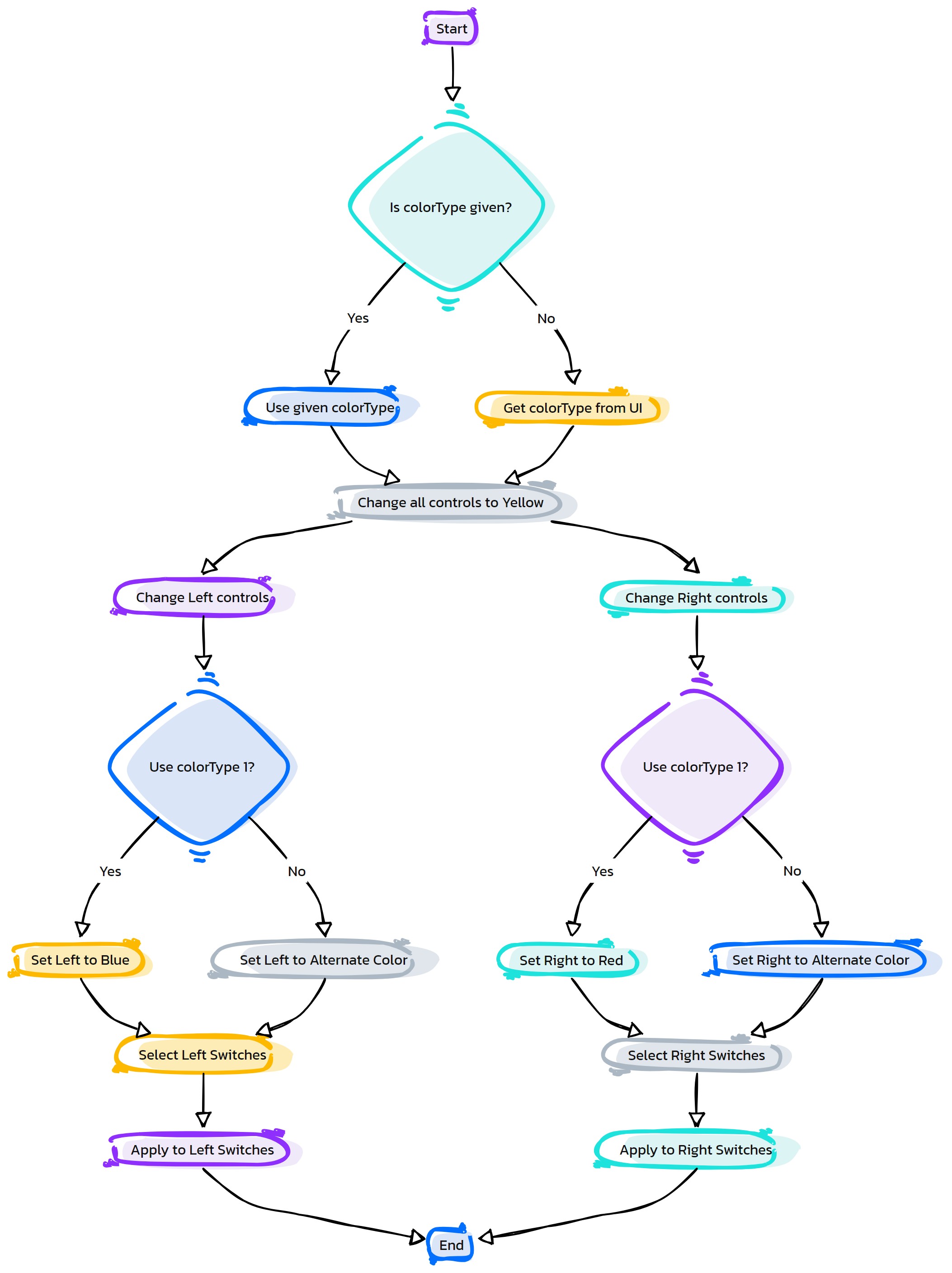
- Flow Chart Description:
This flowchart illustrates the as_ControlColors function:
The process starts by checking if a color type is provided. If not, it retrieves the color type from the Maya UI.
All control objects are initially set to a yellow color.
Left-side controls are then selected and set to blue or an alternate color based on the color type.
Right-side controls are selected next and set to red or pink, also depending on the color type.
The function ends after applying the specified colors to the controls.
- EasyRig.as_CreateBreastsRig(self)#
[shArgs : None]
Purpose:
:: The as_CreateBreastsRig function is designed to create a dynamic and adjustable rig for the breasts in a character model, enhancing the realism and flexibility of animations in Autodesk Maya.
Code Example:
>>> as_CreateBreastsRig()
# This example creates a breasts rig for a character model.
graph TB Start[("fa:fa-play Start")] --> PrepCurve[("/fas:fa-vector-square Prepare Curve")] PrepCurve --> CreateJoints[("/fas:fa-sitemap Create Joints")] CreateJoints --> OrientJoints[("/fas:fa-redo-alt Orient Joints")] OrientJoints --> ParentToSpine[("/fas:fa-link Parent to Spine")] ParentToSpine --> MirrorJoints[("/fas:fa-clone Mirror Joints")] MirrorJoints --> CreateIK[("/fas:fa-arrows-alt Create IK Handles")] CreateIK --> CreateCtrls[("/fas:fa-hand-pointer Create Controls")] CreateCtrls --> MirroringCtrls[("/fas:fa-clone Mirroring Controls")] MirroringCtrls --> ConnectCtrls[("/fas:fa-link Connect Controls to IK")] ConnectCtrls --> ParentCtrls[("/fas:fa-link Parent Controls")] ParentCtrls --> End[("fas:fa-stop End")] style Start fill:#00cc00,stroke:#000,stroke-width:3px style PrepCurve fill:#99ff99,stroke:#000,stroke-width:2px style CreateJoints fill:#99ff99,stroke:#000,stroke-width:2px style OrientJoints fill:#99ff99,stroke:#000,stroke-width:2px style ParentToSpine fill:#99ff99,stroke:#000,stroke-width:2px style MirrorJoints fill:#99ff99,stroke:#000,stroke-width:2px style CreateIK fill:#99ff99,stroke:#000,stroke-width:2px style CreateCtrls fill:#99ff99,stroke:#000,stroke-width:2px style MirroringCtrls fill:#99ff99,stroke:#000,stroke-width:2px style ConnectCtrls fill:#99ff99,stroke:#000,stroke-width:2px style ParentCtrls fill:#99ff99,stroke:#000,stroke-width:2px style End fill:#ff6666,stroke:#000,stroke-width:3px- Flow Chart Description:
The as_CreateBreastsRig function’s flowchart depicts the following sequence:
The process starts by preparing the curve for rig creation.
Joints are created along the curve to form the basic structure.
These joints are oriented correctly to match the body’s anatomy.
The joints are then parented to the spine for proper movement correlation.
The joints on one side are mirrored to the other side for symmetry.
IK handles are created to control the movement of the breasts.
Controls for IK handles are created for easier manipulation.
These controls are mirrored to ensure symmetrical control on both sides.
The controls are then connected to the IK handles for effective rigging.
Finally, the controls are parented appropriately for hierarchical structure.
The process concludes with a fully functional breasts rig setup.
- EasyRig.as_CreateEyeSetup(self)#
[shArgs : None]
Purpose:
:: The as_CreateEyeSetup function is designed to create a detailed eye rig for a character in Autodesk Maya. This includes setting up eye joints, controls, and aim constraints to enable realistic eye movements.
Code Example:
>>> as_CreateEyeSetup()
# This example will initiate the process of creating an eye setup for a character rig.
graph TB Start[("fa:fa-play Start")] --> SetGlobalVariables["/fas:fa-cog Set Global Variables"] SetGlobalVariables --> RenameEyes["/fas:fa-edit Rename Eyes"] RenameEyes --> CreateEyeJoints["/fas:fa-bone Create Eye Joints"] CreateEyeJoints --> CreateEyesMainCtrl["/fas:fa-eye Create Eyes Main Control"] CreateEyesMainCtrl --> CreateLeftEyeCtrl["/fas:fa-eye Create Left Eye Control"] CreateEyesMainCtrl --> CreateRightEyeCtrl["/fas:fa-eye Create Right Eye Control"] CreateLeftEyeCtrl --> AimConstraintLEye["/fas:fa-bullseye Aim Constraint L Eye"] CreateRightEyeCtrl --> AimConstraintREye["/fas:fa-bullseye Aim Constraint R Eye"] AimConstraintLEye --> BindLEyeJnt["/fas:fa-link Bind L Eye Joint"] AimConstraintREye --> BindREyeJnt["/fas:fa-link Bind R Eye Joint"] BindLEyeJnt --> End[("fas:fa-stop End")] BindREyeJnt --> End style Start fill:#00cc00,stroke:#000,stroke-width:3px style SetGlobalVariables fill:#ff9999,stroke:#000,stroke-width:2px style RenameEyes fill:#99ccff,stroke:#000,stroke-width:2px style CreateEyeJoints fill:#ffcc00,stroke:#000,stroke-width:2px style CreateEyesMainCtrl fill:#99ff99,stroke:#000,stroke-width:2px style CreateLeftEyeCtrl fill:#ff9999,stroke:#000,stroke-width:2px style CreateRightEyeCtrl fill:#99ccff,stroke:#000,stroke-width:2px style AimConstraintLEye fill:#ffcc00,stroke:#000,stroke-width:2px style AimConstraintREye fill:#99ff99,stroke:#000,stroke-width:2px style BindLEyeJnt fill:#cc99ff,stroke:#000,stroke-width:2px style BindREyeJnt fill:#99ff99,stroke:#000,stroke-width:2px style End fill:#ff6666,stroke:#000,stroke-width:3px- Flow Chart Description:
The as_CreateEyeSetup function follows these steps:
Sets global variables such as joint names and group names.
Renames eye objects for consistency and usability.
Creates eye joints and positions them according to the character’s anatomy.
Generates the main control for the eyes, used for overall movement.
Creates a control for the left eye with appropriate settings and position.
Creates a control for the right eye similar to the left eye.
Applies aim constraints to the left eye for directional control.
Applies aim constraints to the right eye, mirroring the left.
Binds the left eye joint to the character’s mesh for skinning.
Binds the right eye joint, completing the eye rig setup.
- EasyRig.as_CreateFingerJoints(self)#
[shArgs : palmCurve, thumbCurve, indexCurve, middleCurve, ringCurve, pinkyCurve]
Purpose:
:: The as_CreateFingerJoints function is used in Autodesk Maya to create finger joints for a character’s hands. It supports both left-hand (LH) and right-hand (RH) side fingers, generating joints based on specific curves for the thumb, index, middle, ring, and pinky fingers.
Code Example:
>>> as_CreateFingerJoints()
# This example invokes the function to create finger joints for both hands based on predefined curves for each finger.
graph TB Start[("fa:fa-play Start")] --> DefineFingerNames["/fas:fa-hand-paper Define Finger Names"] DefineFingerNames --> CreateJointsLH{"/fas:fa-hand-left Create Joints LH"} CreateJointsLH --> OrientJointsLH["/fas:fa-sync-alt Orient Joints LH"] OrientJointsLH --> CreatePalmJointsLH["/fas:fa-hand-holding Create Palm Joints LH"] CreatePalmJointsLH --> AddBaseJointsLH{"/fas:fa-plus-square Add Base Joints LH"} AddBaseJointsLH --> CheckAsymmetry{{"/fas:fa-balance-scale Check Asymmetry"}} CheckAsymmetry -- "If asymmetry is enabled" --> MirrorJointsRH{"/fas:fa-magic Mirror Joints RH"} CheckAsymmetry -- "If asymmetry is not enabled" --> CreateJointsRH{"/fas:fa-hand-right Create Joints RH"} MirrorJointsRH --> End[("fas:fa-stop End")] CreateJointsRH --> OrientJointsRH["/fas:fa-sync-alt Orient Joints RH"] OrientJointsRH --> CreatePalmJointsRH["/fas:fa-hand-holding Create Palm Joints RH"] CreatePalmJointsRH --> AddBaseJointsRH{"/fas:fa-plus-square Add Base Joints RH"} AddBaseJointsRH --> End style Start fill:#00cc00,stroke:#000,stroke-width:3px style DefineFingerNames fill:#ffcc00,stroke:#000,stroke-width:2px style CreateJointsLH fill:#ff9999,stroke:#000,stroke-width:2px style OrientJointsLH fill:#99ccff,stroke:#000,stroke-width:2px style CreatePalmJointsLH fill:#cc99ff,stroke:#000,stroke-width:2px style AddBaseJointsLH fill:#99ff99,stroke:#000,stroke-width:2px style CheckAsymmetry fill:#ff6666,stroke:#000,stroke-width:2px style MirrorJointsRH fill:#66ccff,stroke:#000,stroke-width:2px style CreateJointsRH fill:#ccccff,stroke:#000,stroke-width:2px style OrientJointsRH fill:#ccffcc,stroke:#000,stroke-width:2px style CreatePalmJointsRH fill:#99ccff,stroke:#000,stroke-width:2px style AddBaseJointsRH fill:#ff9999,stroke:#000,stroke-width:2px style End fill:#ff6666,stroke:#000,stroke-width:3px- Flow Chart Description:
The as_CreateFingerJoints function performs the following steps:
Define Finger Names: Sets the names for fingers and corresponding curves.
Create Joints LH: Generates joints for the left hand’s fingers based on the defined curves.
Orient Joints LH: Correctly orients the left hand finger joints.
Create Palm Joints LH: Constructs additional joints at the left palm for the fingers’ bases.
Add Base Joints LH: Adds base joints for individual fingers on the left hand.
Check Asymmetry: Determines whether to create joints for the right hand or mirror the left hand’s joints based on asymmetry setting.
Mirror Joints RH: Mirrors the left hand’s joints to the right hand if asymmetry is enabled.
Create Joints RH: Generates joints for the right hand’s fingers if asymmetry is not enabled.
Orient Joints RH: Correctly orients the right hand finger joints.
Create Palm Joints RH: Constructs additional joints at the right palm for the fingers’ bases.
Add Base Joints RH: Adds base joints for individual fingers on the right hand.
The process concludes with properly setup finger joints for both hands.
- EasyRig.as_CreateFingerJoints_R(self)#
[shArgs : palmCurve_R, thumbCurve_R, indexCurve_R, middleCurve_R, ringCurve_R, pinkyCurve_R]
Purpose:
:: The as_CreateFingerJoints_R function generates the right hand’s finger joints in Autodesk Maya, based on curves representing the thumb, index, middle, ring, and pinky fingers.
Code Example:
>>> as_CreateFingerJoints_R()
# This example constructs the right hand's finger joints based on predefined curves for each finger.
graph TB Start[("fa:fa-play Start")] --> DuplicateCurves["/fas:fa-copy Duplicate Curves"] DuplicateCurves --> CreateMirrorGroup{"/fas:fa-object-group Create Mirror Group"} CreateMirrorGroup --> GenerateFingerJoints{"/fas:fa-hand-paper Generate Finger Joints"} GenerateFingerJoints --> SetJointOrientation{"/fas:fa-tools Set Joint Orientation"} SetJointOrientation --> CreatePalmJoints["/fas:fa-hand-holding Create Palm Mid Joints"] CreatePalmJoints --> AddBaseJoints{"/fas:fa-plus-square Add Base Joints"} AddBaseJoints --> MirrorPalmJoints{"/fas:fa-magic Mirror Palm Joints"} MirrorPalmJoints --> DeleteOriginals{"/fas:fa-trash-alt Delete Originals"} DeleteOriginals --> OrientFingerJoints{"/fas:fa-sync-alt Orient Finger Joints"} OrientFingerJoints --> End[("fas:fa-stop End")] style Start fill:#00cc00,stroke:#000,stroke-width:3px style DuplicateCurves fill:#ffcc00,stroke:#000,stroke-width:2px style CreateMirrorGroup fill:#ff9999,stroke:#000,stroke-width:2px style GenerateFingerJoints fill:#99ccff,stroke:#000,stroke-width:2px style SetJointOrientation fill:#cc99ff,stroke:#000,stroke-width:2px style CreatePalmJoints fill:#99ff99,stroke:#000,stroke-width:2px style AddBaseJoints fill:#ff6666,stroke:#000,stroke-width:2px style MirrorPalmJoints fill:#66ccff,stroke:#000,stroke-width:2px style DeleteOriginals fill:#ccccff,stroke:#000,stroke-width:2px style OrientFingerJoints fill:#ccffcc,stroke:#000,stroke-width:2px style End fill:#ff6666,stroke:#000,stroke-width:3px- Flow Chart Description:
The as_CreateFingerJoints_R function involves the following steps:
Duplicate Curves: Creates duplicates of the right hand’s finger curves.
Create Mirror Group: Generates a mirrored group for the duplicated finger curves.
Generate Finger Joints: Creates joints for each finger based on the mirrored curves.
Set Joint Orientation: Adjusts the orientation of the newly created finger joints.
Create Palm Mid Joints: Constructs additional joints at the palm for the fingers’ bases.
Add Base Joints: Adds base joints for individual fingers.
Mirror Palm Joints: Mirrors the palm joints to the right hand.
Delete Originals: Removes the original left hand finger joints.
Orient Finger Joints: Correctly orients the finger joints on the right hand.
The process concludes with properly setup finger joints for the right hand.
- EasyRig.as_CreateFingerSetup(self)#
[shArgs : palmCurve, thumbCurve, indexCurve, ringCurve, middleCurve, pinkyCurve, ikGrp]
Purpose:
:: The as_CreateFingerSetup function in Autodesk Maya generates a comprehensive setup for finger controls, including IK handles and control attributes for curl, spread, and rotation. It supports asymmetric rigging, allowing individual setup for left and right hands.
Code Example:
>>> as_CreateFingerSetup()
# This example runs the function to create finger setup for a character rig, with options for asymmetry and palm extras.
graph TB Start[("fa:fa-play Start")] --> CreateJointLists["/fas:fa-list-ol Create Joint Lists"] CreateJointLists --> CreateCtrlsLH{"/fas:fa-hand-paper Create Ctrls LH"} CreateCtrlsLH --> CreateCtrlsRH{"/fas:fa-hand-paper Create Ctrls RH"} CreateCtrlsRH --> CreateFistSetupLH["/fas:fa-fist-raised Create Fist Setup LH"] CreateFistSetupLH --> CreateFistSetupRH["/fas:fa-fist-raised Create Fist Setup RH"] CreateFistSetupRH --> CheckPalmExtras{{"/fas:fa-plus Check Palm Extras"}} CheckPalmExtras --"If enabled" --> CreatePalmExtrasLH["/fas:fa-hand-holding Create Palm Extras LH"] CreatePalmExtrasLH --> CreatePalmExtrasRH["/fas:fa-hand-holding Create Palm Extras RH"] CheckPalmExtras --"If not enabled" --> End[("fas:fa-stop End")] CreatePalmExtrasRH --> End style Start fill:#00cc00,stroke:#000,stroke-width:3px style CreateJointLists fill:#ffcc00,stroke:#000,stroke-width:2px style CreateCtrlsLH fill:#ff9999,stroke:#000,stroke-width:2px style CreateCtrlsRH fill:#99ccff,stroke:#000,stroke-width:2px style CreateFistSetupLH fill:#cc99ff,stroke:#000,stroke-width:2px style CreateFistSetupRH fill:#99ff99,stroke:#000,stroke-width:2px style CheckPalmExtras fill:#ff6666,stroke:#000,stroke-width:2px style CreatePalmExtrasLH fill:#66ccff,stroke:#000,stroke-width:2px style CreatePalmExtrasRH fill:#ccccff,stroke:#000,stroke-width:2px style End fill:#ff6666,stroke:#000,stroke-width:3px- Flow Chart Description:
The as_CreateFingerSetup function carries out these steps:
Create Joint Lists: Establishes lists of finger joints for both left and right hands.
Create Ctrls LH: Constructs finger controls for the left hand, including IK setup and attributes for curl, spread, etc.
Create Ctrls RH: Replicates the left hand’s finger control setup for the right hand.
Create Fist Setup LH: Sets up the fist control for the left hand, integrating IK handles and constraints.
Create Fist Setup RH: Mirrors the fist setup from the left hand to the right hand.
Check Palm Extras: Decides whether to include additional palm controls based on user settings.
Create Palm Extras LH: Adds extra palm controls like palm tip and mid controls for the left hand, if enabled.
Create Palm Extras RH: Replicates the left hand’s palm extras for the right hand, if enabled.
The process concludes with a complete finger control setup for both hands, including optional palm extras.
- EasyRig.as_CreateHandsSetup(self)#
[shArgs : asymRig, refCount, handsCurv=’L_Hands_Curve’]
Purpose:
:: The as_CreateHandsSetup function constructs a comprehensive rig for the hands in Autodesk Maya, focusing on IK/FK switching, clavicle automation, and hand pole control for enhanced animatability and flexibility.
Code Example:
>>> as_CreateHandsSetup()
# This example sets up a detailed hand rig in Maya with IK/FK switching, automated clavicle control, and hand pole controls.
graph TB Start[("fa:fa-play Start")] --> AsymmetryCheck{{"/fas:fa-balance-scale Asymmetry Check"}} AsymmetryCheck --"If asymmetry enabled" --> AsymmetricSetup["/fas:fa-hands-helping Asymmetric Setup"] AsymmetryCheck --"Otherwise" --> SymmetricSetup["/fas:fa-handshake Symmetric Setup"] AsymmetricSetup --> CreateJointsFromCurve{("/fas:fa-drafting-compass Create Joints From Curve")} SymmetricSetup --> CreateJointsFromCurve CreateJointsFromCurve --> ElbowAlignment{("/fas:fa-arrows-alt-h Align Elbow Jnt")} ElbowAlignment --> DuplicateHandJoints{("/fas:fa-clone Duplicate Hand Joints")} DuplicateHandJoints --> MirrorJoints{("/fas:fa-magic Mirror Joints")} MirrorJoints --> IKFKMixJoints{("/fas:fa-exchange-alt Create IK/FK Mix Joints")} IKFKMixJoints --> CreateHandIK{("/fas:fa-hand-paper Create Hand IK")} CreateHandIK --> IKFKSwitchCreation{("/fas:fa-toggle-on Create IK/FK Switch")} IKFKSwitchCreation --> CreateIKCtrl{("/fas:fa-cursor Create IK Ctrl")} CreateIKCtrl --> CreateHandPoleCtrl{("/fas:fa-location-arrow Create Hand Pole Ctrl")} CreateHandPoleCtrl --> CreateFKCtrls{("/fas:fa-hands Create FK Ctrls")} CreateFKCtrls --> ClavicleSetup{("/fas:fa-bone Clavicle Setup")} ClavicleSetup --> AutoClavicleSetup{("/fas:fa-robot Auto Clavicle Setup")} AutoClavicleSetup --> SpaceSwitchSetup{("/fas:fa-exchange-alt Space Switch Setup")} SpaceSwitchSetup --> End[("fas:fa-stop End")] style Start fill:#00cc00,stroke:#000,stroke-width:3px style AsymmetryCheck fill:#ffcc00,stroke:#000,stroke-width:2px style AsymmetricSetup fill:#ff9999,stroke:#000,stroke-width:2px style SymmetricSetup fill:#99ccff,stroke:#000,stroke-width:2px style CreateJointsFromCurve fill:#cc99ff,stroke:#000,stroke-width:2px style ElbowAlignment fill:#99ff99,stroke:#000,stroke-width:2px style DuplicateHandJoints fill:#ff6666,stroke:#000,stroke-width:2px style MirrorJoints fill:#66ccff,stroke:#000,stroke-width:2px style IKFKMixJoints fill:#ccccff,stroke:#000,stroke-width:2px style CreateHandIK fill:#ccffcc,stroke:#000,stroke-width:2px style IKFKSwitchCreation fill:#ffcc99,stroke:#000,stroke-width:2px style CreateIKCtrl fill:#ff99cc,stroke:#000,stroke-width:2px style CreateHandPoleCtrl fill:#99ccff,stroke:#000,stroke-width:2px style CreateFKCtrls fill:#cc99ff,stroke:#000,stroke-width:2px style ClavicleSetup fill:#99ff99,stroke:#000,stroke-width:2px style AutoClavicleSetup fill:#ff6666,stroke:#000,stroke-width:2px style SpaceSwitchSetup fill:#66ccff,stroke:#000,stroke-width:2px style End fill:#ff6666,stroke:#000,stroke-width:3px- Flow Chart Description:
The as_CreateHandsSetup function follows these steps:
Check for Asymmetry: Determines if asymmetric rigging is enabled.
Asymmetric/Symmetric Setup: Generates joints based on the selected mode (asymmetric/symmetric).
Create Joints From Curve: Forms joints along the hands curve.
Align Elbow Jnt: Adjusts elbow joint alignment for natural deformation.
Duplicate Hand Joints: Creates FK, IK, and Auto joints.
Mirror Joints: Mirrors hand joints to the other side if symmetrical setup is chosen.
Create IK/FK Mix Joints: Forms joints for IK/FK mixing, particularly for bendy setups.
Create Hand IK: Sets up IK handles for hand animation.
Create IK/FK Switch: Implements a system for switching between IK and FK modes.
Create IK Ctrl: Crafts IK controls for hand manipulation.
Create Hand Pole Ctrl: Develops pole vector controls for IK hands.
Create FK Ctrls: Establishes FK controls for the hand joints.
Clavicle Setup: Sets up clavicle joints and controls for shoulder movement.
Auto Clavicle Setup: Automates clavicle movement in relation to hand movement.
Space Switch Setup: Implements space switching for hand controls to various parent spaces.
The process ends after completing all steps.
- EasyRig.as_CreateHeadNeckSetup(self)#
[shArgs : neckCurv=’Neck_Curve’, setupType=’Basic’]
Purpose:
:: The as_CreateHeadNeckSetup function facilitates the creation of head and neck rig setups in Autodesk Maya, offering different types of setups such as Basic, IK_FK, or Skeleton based on the user’s selection.
Code Example:
>>> as_CreateHeadNeckSetup()
# This example creates a head and neck setup based on the 'Neck_Curve' and the chosen setup type in Maya.
graph TB Start[("fa:fa-play Start")] --> ChooseSetupType{("/fas:fa-list-ol Choose Setup Type")} ChooseSetupType --"If Basic" --> HeadNeckSetupBasic[("/fas:fa-user-circle Head Neck Setup Basic")] ChooseSetupType --"If IK_FK" --> HeadNeckSetupIKFK[("/fas:fa-user-alt Head Neck Setup IK_FK")] ChooseSetupType --"If Skeleton" --> HeadNeckSetupSkeleton[("/fas:fa-user-ninja Head Neck Setup Skeleton")] HeadNeckSetupBasic --> End[("fas:fa-stop End")] HeadNeckSetupIKFK --> End HeadNeckSetupSkeleton --> End style Start fill:#00cc00,stroke:#000,stroke-width:3px style ChooseSetupType fill:#ffcc00,stroke:#000,stroke-width:2px style HeadNeckSetupBasic fill:#99ccff,stroke:#000,stroke-width:2px style HeadNeckSetupIKFK fill:#cc99ff,stroke:#000,stroke-width:2px style HeadNeckSetupSkeleton fill:#99ff99,stroke:#000,stroke-width:2px style End fill:#ff6666,stroke:#000,stroke-width:3px- Flow Chart Description:
The as_CreateHeadNeckSetup function’s flowchart illustrates the following steps:
The process begins with choosing the setup type for the head and neck rig (Basic, IK_FK, or Skeleton) based on the user’s selection.
- Depending on the chosen setup type, the function proceeds to create the appropriate rig:
Basic: A simple head and neck rig is set up.
IK_FK: An IK-FK blended head and neck rig is created.
Skeleton: A more complex skeleton-based head and neck rig is constructed.
The function concludes once the selected rig setup is complete.
- EasyRig.as_CreateHierarchy(self)#
[shArgs : None]
Purpose:
:: The as_CreateHierarchy function in Maya is designed to create an organized hierarchy for a character rig. :: This function sets up various groups for different rig components like joints, geometry, IK handles, and global controls.
Code Examples:
>>> as_CreateHierarchy()
# This example shows how to create a hierarchical structure for a character rig in Maya using the as_CreateHierarchy function.
graph TB Start[("fa:fa-play Start")] --> ResetGlobalCtrlGrp[("fas:fa-sync-alt Reset Global Ctrl Grp")] ResetGlobalCtrlGrp --> CreateTopGroups[("fas:fa-layer-group Create Top Groups")] CreateTopGroups --> CreateGlobalControl[("fas:fa-globe-americas Create Global Control")] CreateGlobalControl --> CreateTransformGroup[("fas:fa-arrows-alt Create Transform Group")] CreateTransformGroup --> CheckTransGrp[{"fas:fa-question Check TransGrp"}] CheckTransGrp --"If TransGrp exists" --> ParentGlobalCtrlGrp[("fas:fa-link Parent Global Ctrl Grp")] CheckTransGrp --"If TransGrp does not exist" --> End[("fas:fa-stop End")] ParentGlobalCtrlGrp --> CreateControlGroups[("fas:fa-sitemap Create Control Groups")] CreateControlGroups --> CreateJointGroup[("fas:fa-bone Create Joint Group")] CreateJointGroup --> CreateGeometryGroup[("fas:fa-cubes Create Geometry Group")] CreateGeometryGroup --> CreateIKGroup[("fas:fa-cogs Create IK Group")] CreateIKGroup --> AddGlobalCtrlAttributes[("fas:fa-plus-square Add Global Ctrl Attributes")] AddGlobalCtrlAttributes --> CreateGlobalCtrlConnections[("fas:fa-link Create Global Ctrl Connections")] CreateGlobalCtrlConnections --> SetVisibilityAttributes[("fas:fa-eye Set Visibility Attributes")] SetVisibilityAttributes --> End style Start fill:#00cc00,stroke:#000,stroke-width:3px style ResetGlobalCtrlGrp fill:#99ccff,stroke:#000,stroke-width:2px style CreateTopGroups fill:#99ccff,stroke:#000,stroke-width:2px style CreateGlobalControl fill:#99ccff,stroke:#000,stroke-width:2px style CreateTransformGroup fill:#99ccff,stroke:#000,stroke-width:2px style CheckTransGrp fill:#ffcc00,stroke:#000,stroke-width:2px style ParentGlobalCtrlGrp fill:#99ccff,stroke:#000,stroke-width:2px style CreateControlGroups fill:#99ccff,stroke:#000,stroke-width:2px style CreateJointGroup fill:#99ccff,stroke:#000,stroke-width:2px style CreateGeometryGroup fill:#99ccff,stroke:#000,stroke-width:2px style CreateIKGroup fill:#99ccff,stroke:#000,stroke-width:2px style AddGlobalCtrlAttributes fill:#99ccff,stroke:#000,stroke-width:2px style CreateGlobalCtrlConnections fill:#99ccff,stroke:#000,stroke-width:2px style SetVisibilityAttributes fill:#99ccff,stroke:#000,stroke-width:2px style End fill:#ff6666,stroke:#000,stroke-width:3px- Flow Chart Description:
The as_CreateHierarchy function flowchart illustrates the following steps:
The process begins with resetting the global control group.
It then creates top-level groups for organizing different rig components.
A global control is created to manage the overall rig.
A transform group is set up for transformations.
The function checks if the transform group exists.
If the transform group exists, the global control group is parented under it.
The function creates control groups for specific rig parts like hands and legs.
A joint group is created for organizing all the joints in the rig.
A geometry group is set up for managing geometry elements.
An IK group is created for IK handles and related controls.
Additional attributes are added to the global control for enhanced rig management.
Connections are established between the global control and other rig components.
Visibility attributes are set for various groups to control their display in the viewport.
The process concludes after the rig hierarchy is successfully created and organized.
- EasyRig.as_CreateLegSetup(self)#
[shArgs : None]
Purpose:
:: The as_CreateLegSetup function sets up a complete leg rig for a character in Autodesk Maya, including IK/FK switching, reverse foot controls, pole vectors, and bank controls. This setup is essential for animating leg movements and foot mechanics realistically.
Code Example:
>>> as_CreateLegSetup()
# This example will create a complete leg rig setup for a character.
graph TB Start[("fa:fa-play Start")] --> CheckAsymmetry["/fas:fa-balance-scale Check Asymmetry Rig"] CheckAsymmetry --"If asymmetric rig" --> CreateMirroredCurve["/fas:fa-sync-alt Create Mirrored Curve for Right Leg"] CreateMirroredCurve --> CreateJoints["/fas:fa-bone Create Joints for Left Leg"] CreateJoints --> AlignKneeJoint["/fas:fa-arrows-alt-h Align Knee Joint"] AlignKneeJoint --> CreateCOGJoint["/fas:fa-circle Create COG Joint"] CreateCOGJoint --> MirrorJoints["/fas:fa-balance-scale Mirror Joints to Right Leg"] MirrorJoints --> DuplicateJoints["/fas:fa-copy Duplicate FK, IK, and Auto Joints"] DuplicateJoints --> CreateIKFKMixJoints["/fas:fa-exchange-alt Create IK/FK Mix Joints"] CreateIKFKMixJoints --> CreateIKHandles["/fas:fa-hand-paper Create IK Handles"] CreateIKHandles --> CreateIKFKSwitches["/fas:fa-toggle-on Create IK/FK Switches"] CreateIKFKSwitches --> CreateFKControls["/fas:fa-hands Create FK Controls"] CreateFKControls --> CreateReverseFootJoints["/fas:fa-undo-alt Create Reverse Foot Joints"] CreateReverseFootJoints --> CreateIKHandlesForRF["/fas:fa-hand-rock Create IK Handles for Reverse Foot"] CreateIKHandlesForRF --> ApplyConstraints["/fas:fa-link Apply Constraints to IK Handles"] ApplyConstraints --> CreateFootControls["/fas:fa-shoe-prints Create Foot Controls"] CreateFootControls --> ConnectRFAttributes["/fas:fa-chain Connect Reverse Foot Attributes"] ConnectRFAttributes --> CreatePoleVectorControls["/fas:fa-compass Create Pole Vector Controls"] CreatePoleVectorControls --> CreateBankSetup["/fas:fa-sliders-h Create Bank Setup"] CreateBankSetup --> End[("fas:fa-stop End")] style Start fill:#00cc00,stroke:#000,stroke-width:3px style CheckAsymmetry fill:#ff9999,stroke:#000,stroke-width:2px style CreateMirroredCurve fill:#99ccff,stroke:#000,stroke-width:2px style CreateJoints fill:#ffcc00,stroke:#000,stroke-width:2px style AlignKneeJoint fill:#ff9999,stroke:#000,stroke-width:2px style CreateCOGJoint fill:#99ccff,stroke:#000,stroke-width:2px style MirrorJoints fill:#ffcc00,stroke:#000,stroke-width:2px style DuplicateJoints fill:#99ff99,stroke:#000,stroke-width:2px style CreateIKFKMixJoints fill:#ff9999,stroke:#000,stroke-width:2px style CreateIKHandles fill:#99ccff,stroke:#000,stroke-width:2px style CreateIKFKSwitches fill:#ffcc00,stroke:#000,stroke-width:2px style CreateFKControls fill:#99ff99,stroke:#000,stroke-width:2px style CreateReverseFootJoints fill:#ff9999,stroke:#000,stroke-width:2px style CreateIKHandlesForRF fill:#99ccff,stroke:#000,stroke-width:2px style ApplyConstraints fill:#ffcc00,stroke:#000,stroke-width:2px style CreateFootControls fill:#99ff99,stroke:#000,stroke-width:2px style ConnectRFAttributes fill:#ff9999,stroke:#000,stroke-width:2px style CreatePoleVectorControls fill:#99ccff,stroke:#000,stroke-width:2px style CreateBankSetup fill:#ffcc00,stroke:#000,stroke-width:2px style End fill:#ff6666,stroke:#000,stroke-width:3px- Flow Chart Description:
The as_CreateLegSetup function operates as follows:
Checks for asymmetric rig setup.
Creates mirrored curves and joints for the right leg if asymmetric.
Aligns the knee joint for a more natural deformation.
Creates a COG (Center of Gravity) joint and parents leg joints to it.
Mirrors joints to the right leg.
Duplicates joints for FK, IK, and auto setups.
Creates IK/FK mix joints for bendy leg setup.
Generates IK handles for leg movements.
Creates IK/FK switches for seamless transitions.
Establishes FK controls for manual joint rotation.
Constructs reverse foot joints for foot roll and twist.
Applies constraints to IK handles and reverse foot setup.
Creates foot controls for IK leg setup.
Connects reverse foot attributes to foot controls.
Sets up pole vector controls for IK knee direction.
Creates a bank setup for foot banking.
- EasyRig.as_CreateSpineSetup(self)#
[shArgs : None]
Purpose:
:: The as_CreateSpineSetup function provides various options for creating a spine rig in Autodesk Maya, such as Basic, IK-FK, and Skeleton setups, catering to different animation requirements.
Code Example:
>>> as_CreateSpineSetup()
# This example creates a spine rig based on the selected setup type in Autodesk Maya.
graph TB Start[("fa:fa-play Start")] --> SetupType{"/fas:fa-cogs Determine Setup Type"} SetupType -- "Basic Setup" --> BasicSetup[("/fas:fa-sitemap Basic Spine Setup")] SetupType -- "IK-FK Setup" --> IKFKSetup[("/fas:fa-arrows-alt-v IK-FK Spine Setup")] SetupType -- "Skeleton Setup" --> SkeletonSetup[("/fas:fa-bone Skeleton Spine Setup")] BasicSetup --> End[("fas:fa-stop End")] IKFKSetup --> End SkeletonSetup --> End style Start fill:#00cc00,stroke:#000,stroke-width:3px style SetupType fill:#ffcc00,stroke:#000,stroke-width:2px style BasicSetup fill:#99ff99,stroke:#000,stroke-width:2px style IKFKSetup fill:#99ff99,stroke:#000,stroke-width:2px style SkeletonSetup fill:#99ff99,stroke:#000,stroke-width:2px style End fill:#ff6666,stroke:#000,stroke-width:3px- Flow Chart Description:
The as_CreateSpineSetup function’s flowchart describes the following steps:
The process starts by determining the type of spine setup chosen.
If ‘Basic Setup’ is chosen, the function proceeds to create a basic spine rig.
If ‘IK-FK Setup’ is selected, the function creates an IK-FK spine rig for more advanced control.
If ‘Skeleton Setup’ is selected, the function creates a skeleton spine rig, which is more detailed and anatomically accurate.
The process ends with the chosen spine setup completed and ready for use in character animations.
- EasyRig.as_CreateToeJoints(self)#
[shArgs : None]
Purpose:
:: The as_CreateToeJoints function is designed to generate a complete toe joint setup for a character in Autodesk Maya. This setup includes creating toe joints from curves, orienting joints, and establishing FK controls and IK handles for each toe.
Code Example:
>>> as_CreateToeJoints()
# This example will create a complete toe joint setup for a character.
graph TB Start[("fa:fa-play Start")] --> SetGlobalVariables["/fas:fa-cog Set Global Variables"] SetGlobalVariables --> CreateJointsForEachToeCurve["/fas:fa-stream Create Joints for Each Toe Curve"] CreateJointsForEachToeCurve --> OrientToeJoints["/fas:fa-sync-alt Orient Toe Joints"] OrientToeJoints --> CreatePalmMidJoints["/fas:fa-bone Create Palm Mid Joints for Toe Bases"] CreatePalmMidJoints --> ParentToesToBaseJoints["/fas:fa-sitemap Parent Toes to Base Joints"] ParentToesToBaseJoints --> ParentMidJntToRootJnt["/fas:fa-link Parent Mid Joint to Root Joint"] ParentMidJntToRootJnt --> MirrorToRightSide["/fas:fa-balance-scale Mirror to Right Side"] MirrorToRightSide --> ParentToAnkleJnt["/fas:fa-link Parent to Ankle Joint"] ParentToAnkleJnt --> SetupFKForToes["/fas:fa-hands Setup FK for Toes"] SetupFKForToes --> CreateIKForToes["/fas:fa-hand-paper Create IK for Toes"] CreateIKForToes --> End[("fas:fa-stop End")] style Start fill:#00cc00,stroke:#000,stroke-width:3px style SetGlobalVariables fill:#ff9999,stroke:#000,stroke-width:2px style CreateJointsForEachToeCurve fill:#99ccff,stroke:#000,stroke-width:2px style OrientToeJoints fill:#ffcc00,stroke:#000,stroke-width:2px style CreatePalmMidJoints fill:#99ff99,stroke:#000,stroke-width:2px style ParentToesToBaseJoints fill:#ff9999,stroke:#000,stroke-width:2px style ParentMidJntToRootJnt fill:#99ccff,stroke:#000,stroke-width:2px style MirrorToRightSide fill:#ffcc00,stroke:#000,stroke-width:2px style ParentToAnkleJnt fill:#99ff99,stroke:#000,stroke-width:2px style SetupFKForToes fill:#ff9999,stroke:#000,stroke-width:2px style CreateIKForToes fill:#99ccff,stroke:#000,stroke-width:2px style End fill:#ff6666,stroke:#000,stroke-width:3px- Flow Chart Description:
The as_CreateToeJoints function proceeds as follows:
Sets global variables for toe curves, names, and related joints.
Creates joints for each toe based on curves.
Orients the toe joints for proper rotation.
Generates palm mid joints as the base for toes.
Parents each toe’s joints to their corresponding base joints.
Parents the mid joint to the root joint of the rig.
Mirrors the left side toe setup to create the right side.
Parents the mid joint to the respective ankle joint.
Sets up FK controls for each toe.
Creates IK handles for toes to aid in animation.
- EasyRig.as_CreateToesSetup(self)#
[shArgs : None]
Purpose:
:: The as_CreateToesSetup function is designed to establish a comprehensive setup for toes in a character rig within Autodesk Maya. This includes creating toe controls, setting up IK handles, and integrating these components into the hand rig.
Code Example:
>>> as_CreateToesSetup()
# This example will create a complete toe setup for a character rig.
graph TB Start[("fa:fa-play Start")] --> SetGlobalVariables["/fas:fa-cog Set Global Variables"] SetGlobalVariables --> CreatePalmMidJoints["/fas:fa-bone Create Palm Mid Joints"] CreatePalmMidJoints --> MirrorPalmMidJoints["/fas:fa-balance-scale Mirror Palm Mid Joints"] MirrorPalmMidJoints --> ParentMidJntsToHands["/fas:fa-sitemap Parent Mid Joints to Hands"] ParentMidJntsToHands --> CreateToeCtrlLists["/fas:fa-list Create Toe Control Lists"] CreateToeCtrlLists --> CreateToeControls["/fas:fa-hand-paper Create Toe Controls"] CreateToeControls --> CreateFistSetup["/fas:fa-hand-rock Create Fist Setup"] CreateFistSetup --> CreatePalmExtras["/fas:fa-plus-circle Create Palm Extras"] CreatePalmExtras --> End[("fas:fa-stop End")] style Start fill:#00cc00,stroke:#000,stroke-width:3px style SetGlobalVariables fill:#ff9999,stroke:#000,stroke-width:2px style CreatePalmMidJoints fill:#99ccff,stroke:#000,stroke-width:2px style MirrorPalmMidJoints fill:#ffcc00,stroke:#000,stroke-width:2px style ParentMidJntsToHands fill:#99ff99,stroke:#000,stroke-width:2px style CreateToeCtrlLists fill:#ff9999,stroke:#000,stroke-width:2px style CreateToeControls fill:#99ccff,stroke:#000,stroke-width:2px style CreateFistSetup fill:#ffcc00,stroke:#000,stroke-width:2px style CreatePalmExtras fill:#99ff99,stroke:#000,stroke-width:2px style End fill:#ff6666,stroke:#000,stroke-width:3px- Flow Chart Description:
The as_CreateToesSetup function progresses as follows:
Sets global variables for toes setup, including names and hand references.
Creates palm mid joints as a base for toe controls.
Mirrors the palm mid joints to the opposite side of the character.
Parents the mid joints to the corresponding hand joints.
Generates variable lists for toe joints on both left and right sides.
Creates toe controls for fingers and toes, establishing FK control.
Implements a fist setup to control the closing of the hand and fingers.
Adds additional controls for palm and IK setups to enhance rig functionality.
- EasyRig.as_EasyRig(self)#
[shArgs : None]
Purpose:
:: The as_EasyRig function serves as an entry point to the EasyRig rigging system in Autodesk Maya. :: It provides a user-friendly interface for setting up character rigs, starting with eye positioning and including other body parts.
Code Examples:
>>> as_EasyRig()
# This example demonstrates initiating the EasyRig setup process, which opens a dedicated rigging interface in Maya for character rigging.
graph TB Start[("fa:fa-play Start")] --> CheckWindow[("fas:fa-window-maximize Check if Window Exists")] CheckWindow --"If Window Exists" --> RetrieveInputs[("fas:fa-keyboard Retrieve Previous Inputs")] RetrieveInputs --> DeleteExistingWindow[("fas:fa-window-close Delete Existing Window")] DeleteExistingWindow --> LoadUI[("fas:fa-upload Load UI")] LoadUI --> DisplayWindow[("fas:fa-desktop Display Window")] DisplayWindow --> SetPreviousInputs[("fas:fa-redo-alt Set Previous Inputs")] CheckWindow --"If Window Does Not Exist" --> LoadUI SetPreviousInputs --> End[("fas:fa-stop End")] style Start fill:#00cc00,stroke:#000,stroke-width:3px style CheckWindow fill:#ff9999,stroke:#000,stroke-width:2px style RetrieveInputs fill:#99ccff,stroke:#000,stroke-width:2px style DeleteExistingWindow fill:#99ccff,stroke:#000,stroke-width:2px style LoadUI fill:#99ccff,stroke:#000,stroke-width:2px style DisplayWindow fill:#99ccff,stroke:#000,stroke-width:2px style SetPreviousInputs fill:#99ccff,stroke:#000,stroke-width:2px style End fill:#ff6666,stroke:#000,stroke-width:3px- Flow Chart Description:
The as_EasyRig function flowchart illustrates the following process:
It starts by checking if the EasyRig window already exists in Maya.
If the window exists, the function retrieves the previously entered inputs for eye positions, body geometry, and armpit vertex.
It then proceeds to delete the existing window to ensure a fresh start.
Next, the function loads the EasyRig user interface from a specified location or the default Maya scripts directory.
The EasyRig window is then displayed to the user with appropriate width and height settings.
If any previous inputs were retrieved, they are set back into the respective fields in the new window.
The process concludes by making the EasyRig window ready for user interaction, facilitating an easier and more efficient rigging workflow.
- EasyRig.as_EasyRig1(self)#
- EasyRig.as_FinalizeSetup(self)#
[shArgs : None]
Purpose:
:: The as_FinalizeSetup function is designed to finalize the rigging setup in Autodesk Maya. It performs several operations like locking control attributes, hiding various rig elements, creating selection sets, and setting up space switches.
Code Example:
>>> as_FinalizeSetup()
# This example will execute the function to finalize the rigging setup for a character.
graph TB Start[("fa:fa-play Start")] --> SetGlobalVariable["/fas:fa-cog Set Global Variable"] SetGlobalVariable --> LockControlAttributes["/fas:fa-lock Lock Control Attributes"] LockControlAttributes --> HideRigElements["/fas:fa-eye-slash Hide Rig Elements"] HideRigElements --> LockHideJoints["/fas:fa-bone Lock and Hide Joints"] LockHideJoints --> CreateAnnotation["/fas:fa-sticky-note Create Annotation"] CreateAnnotation --> CreateSelectionSet["/fas:fa-object-group Create Selection Set"] CreateSelectionSet --> ColorPlacementControl["/fas:fa-paint-brush Color Placement Control"] ColorPlacementControl --> SetupSpaceSwitches["/fas:fa-exchange-alt Setup Space Switches"] SetupSpaceSwitches --> AddJointAttributes["/fas:fa-tags Add Joint Attributes"] AddJointAttributes --> DefineMoCapAHSS["/fas:fa-user-alt Define MoCap/AHSS"] DefineMoCapAHSS --> SetControlRotateOrder["/fas:fa-redo Set Control Rotate Order"] SetControlRotateOrder --> End[("fas:fa-stop End")] style Start fill:#00cc00,stroke:#000,stroke-width:3px style SetGlobalVariable fill:#ff9999,stroke:#000,stroke-width:2px style LockControlAttributes fill:#99ccff,stroke:#000,stroke-width:2px style HideRigElements fill:#ffcc00,stroke:#000,stroke-width:2px style LockHideJoints fill:#99ff99,stroke:#000,stroke-width:2px style CreateAnnotation fill:#ff9999,stroke:#000,stroke-width:2px style CreateSelectionSet fill:#99ccff,stroke:#000,stroke-width:2px style ColorPlacementControl fill:#ffcc00,stroke:#000,stroke-width:2px style SetupSpaceSwitches fill:#99ff99,stroke:#000,stroke-width:2px style AddJointAttributes fill:#ff9999,stroke:#000,stroke-width:2px style DefineMoCapAHSS fill:#99ccff,stroke:#000,stroke-width:2px style SetControlRotateOrder fill:#ffcc00,stroke:#000,stroke-width:2px style End fill:#ff6666,stroke:#000,stroke-width:3px- Flow Chart Description:
The as_FinalizeSetup function performs the following actions:
Sets a global variable based on the character prefix.
Locks visibility and scale attributes for all controls.
Hides IK handles, curves, and cluster nodes in the scene.
Locks and hides all joints.
Creates an annotation note on the main control.
Generates a selection set for key controls.
Colors and untemplates the placement control.
Sets up space switches for various controls.
Adds custom joint attributes for AHSS (Advanced Human Simulation System) compatibility.
Defines MoCap and AHSS parent-child relationships for specific joints.
Adjusts rotate order for controls to optimize animation workflow.
Concludes the setup process.
- EasyRig.as_GenerateHyperPoints(self)#
[shArgs : None]
Purpose:
:: The as_GenerateHyperPoints function is pivotal in rigging character models in Autodesk Maya. It automates the placement of ‘HyperPoints’, which are critical control points on a 3D character’s rig. These points correspond to various anatomical landmarks like joints, the spine, and extremities. This function intelligently positions these points based on the geometry of the character, ensuring a more accurate and efficient rigging process.
Code Example:
>>> as_GenerateHyperPoints()
# Automates the placement of HyperPoints on a 3D character model in Maya.
graph TB Start[("fa:fa-play Start")] --> HPInit[("/fas:fa-cube Initialize HyperPoints")] HPInit --> CheckBody[("/fas:fa-check-circle Check Body Existence")] CheckBody --"Body Exists" --> QuickHP[("/fas:fa-bolt Quick HyperPoints")] QuickHP --"Quick Mode Selected" --> DuplicateMesh[("/fas:fa-clone Duplicate Mesh")] QuickHP --"Standard Mode" --> DuplicateMesh DuplicateMesh --> SetDisplayType[("/fas:fa-eye Set Display Type")] SetDisplayType --> DefineVariables[("/fas:fa-sliders-h Define Variables")] DefineVariables --> GenerateRoot[("/fas:fa-code Generate Root HyperPoint")] GenerateRoot --> GenerateChest[("/fas:fa-code Generate Chest HyperPoint")] GenerateChest --> GenerateSpine[("/fas:fa-code Generate Spine HyperPoint")] GenerateSpine --> GenerateHead[("/fas:fa-code Generate Head HyperPoint")] GenerateHead --> GenerateJaw[("/fas:fa-code Generate Jaw HyperPoint")] GenerateJaw --> GenerateLimbs[("/fas:fa-code Generate Limbs HyperPoints")] GenerateLimbs --> GenerateHands[("/fas:fa-hand-paper Generate Hands HyperPoints")] GenerateHands --> GenerateFingers[("/fas:fa-hand-rock Generate Fingers HyperPoints")] GenerateFingers --> End[("fas:fa-stop End")] style Start fill:#00cc00,stroke:#000,stroke-width:3px style End fill:#ff6666,stroke:#000,stroke-width:3px- Flow Chart Description:
This flowchart illustrates the as_GenerateHyperPoints function:
The function begins by initializing HyperPoints and checking if the body of the character exists.
It checks if Quick HyperPoints mode is selected. If yes, it duplicates the mesh for a faster process; otherwise, it follows the standard procedure.
Display types for the meshes are set, and essential variables for the process are defined.
Sequentially, the function generates HyperPoints for various parts of the body: Root, Chest, Spine, Head, Jaw, Limbs, Hands, and Fingers.
The HyperPoints are meticulously placed based on the character’s geometry, ensuring accurate positioning for rigging.
- EasyRig.as_HeadNeckSetup_Basic(self)#
[shArgs : neckCurv=’Neck_Curve’, headCurv=’Head_Curve’, jawCurv=’Jaw_Curve’]
Purpose:
:: The as_HeadNeckSetup_Basic function creates a basic rigging setup for the head, neck, and jaw in Autodesk Maya, using specified curve objects to define joint positions.
Code Example:
>>> as_HeadNeckSetup_Basic()
# This example sets up a basic head, neck, and jaw rig in Maya using 'Neck_Curve', 'Head_Curve', and 'Jaw_Curve'.
graph TB Start[("fa:fa-play Start")] --> NeckSetup{("/fas:fa-necklace Neck Setup")} NeckSetup --> HeadSetup{("/fas:fa-head-side Head Setup")} HeadSetup --> JawSetup{("/fas:fa-tooth Jaw Setup")} JawSetup --> ParentJoints{("/fas:fa-link Parent Joints")} ParentJoints --> CreateNeckIK{("/fas:fa-bezier-curve Create Neck IK")} CreateNeckIK --> CreateNeckControl[("/fas:fa-user-circle Create Neck Control")] CreateNeckControl --> CreateHeadControl[("/fas:fa-user-alt Create Head Control")] CreateHeadControl --> CreateNeckIKCurve[("/fas:fa-draw-polygon Create Neck IK Curve")] CreateNeckIKCurve --> SetupClusterNeck{("/fas:fa-object-group Setup Cluster Neck")} SetupClusterNeck --> SetupClusterHead{("/fas:fa-object-group Setup Cluster Head")} SetupClusterHead --> SetupClusterMid{("/fas:fa-object-ungroup Setup Cluster Mid")} SetupClusterMid --> HeadCtrlSpaceSwitch{("/fas:fa-exchange-alt Head Ctrl Space Switch")} HeadCtrlSpaceSwitch --> ConnectJawMovement{("/fas:fa-link Connect Jaw Movement")} ConnectJawMovement --> CreateSetPoseGrp{("/fas:fa-user-check Create Set Pose Grp")} CreateSetPoseGrp --> End[("fas:fa-stop End")] style Start fill:#00cc00,stroke:#000,stroke-width:3px style NeckSetup fill:#ffcc00,stroke:#000,stroke-width:2px style HeadSetup fill:#ff9999,stroke:#000,stroke-width:2px style JawSetup fill:#99ccff,stroke:#000,stroke-width:2px style ParentJoints fill:#cc99ff,stroke:#000,stroke-width:2px style CreateNeckIK fill:#99ff99,stroke:#000,stroke-width:2px style CreateNeckControl fill:#ff6666,stroke:#000,stroke-width:2px style CreateHeadControl fill:#66ccff,stroke:#000,stroke-width:2px style CreateNeckIKCurve fill:#ccccff,stroke:#000,stroke-width:2px style SetupClusterNeck fill:#ccffcc,stroke:#000,stroke-width:2px style SetupClusterHead fill:#ffcc99,stroke:#000,stroke-width:2px style SetupClusterMid fill:#ff99cc,stroke:#000,stroke-width:2px style HeadCtrlSpaceSwitch fill:#cccccc,stroke:#000,stroke-width:2px style ConnectJawMovement fill:#ff99ff,stroke:#000,stroke-width:2px style CreateSetPoseGrp fill:#99cccc,stroke:#000,stroke-width:2px style End fill:#ff6666,stroke:#000,stroke-width:3px- Flow Chart Description:
The as_HeadNeckSetup_Basic function’s flowchart outlines the following steps:
Neck Setup: Creation of neck joints based on ‘Neck_Curve’.
Head Setup: Establishing head joints using ‘Head_Curve’.
Jaw Setup: Forming jaw joints with ‘Jaw_Curve’.
Parent Joints: Hierarchically organizing the created joints.
Create Neck IK: Generating IK handle for neck movement.
Create Neck Control: Crafting a control for the neck.
Create Head Control: Developing a control for the head.
Create Neck IK Curve: Producing a curve to drive the neck IK.
Setup Cluster Neck: Configuring clusters for neck curve CVs.
Setup Cluster Head: Setting up clusters for head curve CVs.
Setup Cluster Mid: Arranging a mid-cluster for intermediate control.
Head Ctrl Space Switch: Implementing space switching for head control.
Connect Jaw Movement: Linking jaw movements to head control.
Create Set Pose Grp: Establishing a group for pose setting.
The process concludes once all steps are completed.
- EasyRig.as_HeadNeckSetup_Skeleton(self, numJnts=7)#
[shArgs : numJnts=7, neckCurv=’Neck_Curve’, headCurv=’Head_Curve’, jawCurv=’Jaw_Curve’]
Purpose:
:: The as_HeadNeckSetup_Skeleton function constructs a detailed skeletal rig for the head and neck in Autodesk Maya, using curve objects to define joint placements and various rigging techniques for enhanced control and realism.
Code Example:
>>> as_HeadNeckSetup_Skeleton(numJnts=7)
# This example sets up a detailed head and neck rig in Maya with 7 joints using 'Neck_Curve', 'Head_Curve', and 'Jaw_Curve'.
graph TB Start[("fa:fa-play Start")] --> NeckSkeletonSetup{("/fas:fa-necklace Neck Skeleton Setup")} NeckSkeletonSetup --> DuplicateFKIKNeck{("/fas:fa-clone Duplicate FK/IK Neck")} DuplicateFKIKNeck --> CreateNeckIKCurve{("/fas:fa-draw-polygon Create Neck IK Curve")} CreateNeckIKCurve --> CreateNeckIKCtrls{("/fas:fa-hand-point-up Create Neck IK Ctrls")} CreateNeckIKCtrls --> SkinNeckCurve[("/fas:fa-syringe Skin Neck Curve")] SkinNeckCurve --> SetupNeckConstraints{("/fas:fa-link Setup Neck Constraints")} SetupNeckConstraints --> CreateNeckTwist{("/fas:fa-sync-alt Create Neck Twist")} CreateNeckTwist --> CreateFKCtrlsNeck[("/fas:fa-user-cog Create FK Ctrls Neck")] CreateFKCtrlsNeck --> HeadSetup{("/fas:fa-head-side Head Setup")} HeadSetup --> JawSetup{("/fas:fa-tooth Jaw Setup")} JawSetup --> FinalIKFKConnections{("/fas:fa-exchange-alt Final IK/FK Connections")} FinalIKFKConnections --> End[("fas:fa-stop End")] style Start fill:#00cc00,stroke:#000,stroke-width:3px style NeckSkeletonSetup fill:#ffcc00,stroke:#000,stroke-width:2px style DuplicateFKIKNeck fill:#ff9999,stroke:#000,stroke-width:2px style CreateNeckIKCurve fill:#99ccff,stroke:#000,stroke-width:2px style CreateNeckIKCtrls fill:#cc99ff,stroke:#000,stroke-width:2px style SkinNeckCurve fill:#99ff99,stroke:#000,stroke-width:2px style SetupNeckConstraints fill:#ff6666,stroke:#000,stroke-width:2px style CreateNeckTwist fill:#66ccff,stroke:#000,stroke-width:2px style CreateFKCtrlsNeck fill:#ccccff,stroke:#000,stroke-width:2px style HeadSetup fill:#ccffcc,stroke:#000,stroke-width:2px style JawSetup fill:#ffcc99,stroke:#000,stroke-width:2px style FinalIKFKConnections fill:#ff99cc,stroke:#000,stroke-width:2px style End fill:#ff6666,stroke:#000,stroke-width:3px- Flow Chart Description:
The as_HeadNeckSetup_Skeleton function’s flowchart outlines these steps:
Neck Skeleton Setup: Generating neck joints from ‘Neck_Curve’.
Duplicate FK/IK Neck: Creating FK and IK duplicates for the neck joints.
Create Neck IK Curve: Producing a curve to drive the neck IK setup.
Create Neck IK Ctrls: Crafting IK controls for neck manipulation.
Skin Neck Curve: Binding skin joints to the neck curve for deformation.
Setup Neck Constraints: Implementing constraints for neck movement.
Create Neck Twist: Establishing a twist system for neck rotation.
Create FK Ctrls Neck: Developing FK controls for the neck joints.
Head Setup: Setting up head joints and controls.
Jaw Setup: Forming jaw joints and linking them to the head.
Final IK/FK Connections: Establishing IK/FK switches and connections for the complete setup.
The process concludes once all steps are executed.
- EasyRig.as_QuickSetup(self)#
[shArgs : None]
Purpose:
:: The as_QuickSetup function serves as a higher-level function that sequentially calls as_QuickSetup01 and as_QuickSetup02. These two functions are part of an automated rigging process in Autodesk Maya, typically handling specific stages of the rigging procedure.
Code Example:
>>> as_QuickSetup()
# This example executes the function, triggering the execution of `as_QuickSetup01` followed by `as_QuickSetup02` as part of a rigging process.
graph TB Start[("fa:fa-play Start")] --> CallFirstFunction["/fas:fa-cogs Call as_QuickSetup01"] CallFirstFunction --"Function executed"--> CallSecondFunction["/fas:fa-cogs Call as_QuickSetup02"] CallSecondFunction --"Function executed"--> End[("fas:fa-stop End")] style Start fill:#00cc00,stroke:#000,stroke-width:3px style CallFirstFunction fill:#99ccff,stroke:#000,stroke-width:2px style CallSecondFunction fill:#99ccff,stroke:#000,stroke-width:2px style End fill:#ff6666,stroke:#000,stroke-width:3px- Flow Chart Description:
The as_QuickSetup function performs the following steps:
It begins by calling the as_QuickSetup01 function. This is the first stage of a predefined rigging process.
Upon completion of as_QuickSetup01, it proceeds to call as_QuickSetup02, which represents the next stage in the rigging process.
After the execution of as_QuickSetup02, the overall function completes its operation.
- EasyRig.as_QuickSetup01(self)#
[shArgs : None]
Purpose:
:: The as_QuickSetup01 function is part of an automated rigging system in Autodesk Maya, designed to streamline the initial stages of character rigging. It primarily handles the creation of a hierarchy structure, spine setup, and optionally, head, neck, and hand setups including finger joints.
Code Example:
>>> as_QuickSetup01()
# Executes the initial setup process for character rigging in Autodesk Maya.
graph TB Start[("fa:fa-play Start")] --> CloseWindows["/fas:fa-window-close Close Open Windows"] CloseWindows --"Windows closed"--> CreateHierarchy["/fas:fa-sitemap Create Hierarchy"] CreateHierarchy --"Hierarchy created"--> CreateSpineSetup["/fas:fa-spine Create Spine Setup"] CreateSpineSetup --> CheckHeadNeck["{{fa:fa-question-circle Check Head and Neck Rig Option}}"] CheckHeadNeck --"If enabled"--> CreateHeadNeckSetup["/fas:fa-user-headset Create Head and Neck Setup"] CheckHeadNeck --"If not enabled"--> CheckHandsRig{{"fa:fa-question-circle Check Hands Rig Option"}} CreateHeadNeckSetup --> CheckHandsRig{{"fa:fa-question-circle Check Hands Rig Option"}} CheckHandsRig --"If enabled"--> CreateHandsSetup["/fas:fa-hand-paper Create Hands Setup"] CreateHandsSetup --"If asymmetry enabled"--> CreateFingerJoints_R["/fas:fa-hand-paper Create Right Hand Finger Joints"] CreateHandsSetup --"Proceed to"--> CreateFingerJoints["/fas:fa-hand-paper Create Finger Joints"] CreateFingerJoints_R --> CreateFingerJoints CreateFingerJoints --> End[("fas:fa-stop End")] style Start fill:#00cc00,stroke:#000,stroke-width:3px style CloseWindows fill:#ff9999,stroke:#000,stroke-width:2px style CreateHierarchy fill:#99ccff,stroke:#000,stroke-width:2px style CreateSpineSetup fill:#99ccff,stroke:#000,stroke-width:2px style CheckHeadNeck fill:#ffcc00,stroke:#000,stroke-width:2px style CreateHeadNeckSetup fill:#99ccff,stroke:#000,stroke-width:2px style CheckHandsRig fill:#ffcc00,stroke:#000,stroke-width:2px style CreateHandsSetup fill:#99ccff,stroke:#000,stroke-width:2px style CreateFingerJoints_R fill:#99ccff,stroke:#000,stroke-width:2px style CreateFingerJoints fill:#99ccff,stroke:#000,stroke-width:2px style End fill:#ff6666,stroke:#000,stroke-width:3px- Flow Chart Description:
The as_QuickSetup01 function performs the following steps:
Begins by closing any open windows to clear the workspace.
Creates the basic hierarchy structure required for rigging.
Sets up the spine rigging components.
Checks if the option for Head and Neck rigging is enabled. If so, it proceeds to set up the head and neck rig.
Checks if the option for Hands rigging is enabled. If so, it proceeds to set up the hands rig.
Within the hands setup, it checks for asymmetry. If asymmetry is enabled, it first creates finger joints for the right hand.
Finally, it creates finger joints for the specified rigging setup.
- EasyRig.as_QuickSetup02(self)#
[shArgs : None]
Purpose:
:: The as_QuickSetup02 function continues the automated rigging process in Autodesk Maya. It handles the creation of fingers, legs, toes, eyes, bendy setups, and finalizes the rig setup, including optional features like breast rigging.
Code Example:
>>> as_QuickSetup02()
# Completes the advanced stages of character rigging in Autodesk Maya.
graph TB Start[("fa:fa-play Start")] --> CheckHandsRig01{{"/fas:fa-question-circle Check Hands Rig Option"}} CheckHandsRig01 --"If enabled"--> CreateFingerSetup["/fas:fa-hand-paper Create Finger Setup"] CheckHandsRig01 --"If not enabled"--> CheckLegsRig{{"/fas:fa-question-circle Check Legs Rig Option"}} CreateFingerSetup --> CheckLegsRig{{"/fas:fa-question-circle Check Legs Rig Option"}} CheckLegsRig --"If enabled"--> CreateLegSetup["/fas:fa-walking Create Leg Setup"] CheckLegsRig --"If not enabled"--> CheckEyesSetup{{"/fas:fa-eye Check Eyes Setup Option"}} CreateLegSetup --> CheckCreateToes{{"/fas:fa-question-circle Check Create Toes Option"}} CheckCreateToes --"If enabled"--> CreateToeJoints["/fas:fa-shoe-prints Create Toe Joints"] CheckCreateToes --"If not enabled"--> CheckEyesSetup{{"/fas:fa-eye Check Eyes Setup Option"}} CreateToeJoints --> CheckEyesSetup{{"/fas:fa-eye Check Eyes Setup Option"}} CheckEyesSetup --"Try executing"--> CreateEyeSetup["/fas:fa-eye Create Eye Setup"] CreateEyeSetup --"Proceed to"--> CheckBendySetup{{"/fas:fa-ruler-combined Check Bendy Setup Option"}} CheckBendySetup --"If enabled"--> CheckHandsRig02{{"/fas:fa-question-circle Check Hands Rig Option"}} CheckBendySetup --"If not enabled"--> ActivateSetPose["/fas:fa-clipboard-list Activate Set Pose"] CheckHandsRig02 --"If enabled"--> BendySetupHands["/fas:fa-hand-paper Bendy Setup Hands"] CheckHandsRig02 --"If not enabled"--> CheckLegsRig02{{"/fas:fa-question-circle Check Legs Rig Option"}} BendySetupHands --> CheckLegsRig02{{"/fas:fa-question-circle Check Legs Rig Option"}} CheckLegsRig02 --"If enabled"--> BendySetupLegs["/fas:fa-walking Bendy Setup Legs"] CheckLegsRig02 --"If not enabled"--> ActivateSetPose["/fas:fa-clipboard-list Activate Set Pose"] BendySetupLegs --> ActivateSetPose ActivateSetPose --> ControlColors["/fas:fa-palette Control Colors"] ControlColors --> FinalizeSetup["/fas:fa-tools Finalize Setup"] FinalizeSetup --> CheckBreastsRig{{"/fas:fa-question-circle Check Breasts Rig Option"}} CheckBreastsRig --"If enabled"--> CreateBreastsRig["/fas:fa-female Create Breasts Rig"] CheckBreastsRig --"If not enabled"--> CreateAnimCtrlsSet["/fas:fa-object-group Create Animation Controls Set"] CreateBreastsRig --> CreateAnimCtrlsSet CreateAnimCtrlsSet --> End[("fas:fa-stop End")] style Start fill:#00cc00,stroke:#000,stroke-width:3px style CheckHandsRig01 fill:#ffcc00,stroke:#000,stroke-width:2px style CreateFingerSetup fill:#99ccff,stroke:#000,stroke-width:2px style CheckLegsRig fill:#ffcc00,stroke:#000,stroke-width:2px style CreateLegSetup fill:#99ccff,stroke:#000,stroke-width:2px style CheckCreateToes fill:#ffcc00,stroke:#000,stroke-width:2px style CreateToeJoints fill:#99ccff,stroke:#000,stroke-width:2px style CheckEyesSetup fill:#ffcc00,stroke:#000,stroke-width:2px style CreateEyeSetup fill:#99ccff,stroke:#000,stroke-width:2px style CheckBendySetup fill:#ffcc00,stroke:#000,stroke-width:2px style CheckHandsRig02 fill:#ffcc00,stroke:#000,stroke-width:2px style BendySetupHands fill:#99ccff,stroke:#000,stroke-width:2px style CheckLegsRig02 fill:#ffcc00,stroke:#000,stroke-width:2px style BendySetupLegs fill:#99ccff,stroke:#000,stroke-width:2px style ActivateSetPose fill:#99ccff,stroke:#000,stroke-width:2px style ControlColors fill:#99ccff,stroke:#000,stroke-width:2px style FinalizeSetup fill:#99ccff,stroke:#000,stroke-width:2px style CheckBreastsRig fill:#ffcc00,stroke:#000,stroke-width:2px style CreateBreastsRig fill:#99ccff,stroke:#000,stroke-width:2px style CreateAnimCtrlsSet fill:#99ccff,stroke:#000,stroke-width:2px style End fill:#ff6666,stroke:#000,stroke-width:3px- Flow Chart Description:
The as_QuickSetup02 function encompasses these key steps:
Checks if the hands rigging option is enabled and creates finger setups accordingly.
Proceeds to check for legs rigging. If enabled, sets up the leg rig, and optionally the toes if the toes option is enabled.
Attempts to create eye setups, and continues even if it fails.
Checks for the bendy setup option. If enabled, performs bendy setups for hands and legs.
Activates set pose functionality and applies control colors.
Finalizes the rig setup, and optionally creates breast rigs if the option is enabled.
Lastly, creates a set for animation controls.
- EasyRig.as_SampleCurves(self)#
- EasyRig.as_SelectMirrorEdge(self)#
[shArgs : None]
Purpose:
:: The as_SelectMirrorEdge function mirrors the selection of edges on a 3D model in Autodesk Maya. It calculates the mirrored position of each selected edge and selects the corresponding edge on the opposite side of the model.
Code Example:
>>> as_SelectMirrorEdge()
# This example will mirror the selection of edges on a 3D model.
graph TB Start[("fa:fa-play Start")] --> GetEdgeList["/fas:fa-list Get Edge List"] GetEdgeList --> InitializeProgressWindow["/fas:fa-spinner Initialize Progress Window"] InitializeProgressWindow --> IterateEdges{"/fas:fa-sync-alt Iterate Through Edges"} IterateEdges --"For each edge" --> CheckProgressWindow{{"/fas:fa-window-maximize Check Progress Window"}} CheckProgressWindow --"If cancelled" --> End[("fas:fa-stop End")] CheckProgressWindow --"Continue" --> CalculateMirrorEdge["/fas:fa-calculator Calculate Mirror Edge"] CalculateMirrorEdge --> UpdateProgressWindow["/fas:fa-tasks Update Progress Window"] UpdateProgressWindow --"Next Edge" --> IterateEdges UpdateProgressWindow --"Completed" --> SelectMirroredEdges["/fas:fa-mouse-pointer Select Mirrored Edges"] SelectMirroredEdges --> CheckEdgeCount{{"/fas:fa-balance-scale Check Edge Count"}} CheckEdgeCount --"If counts match" --> DisplayMatchInfo["/fas:fa-info Display Matching Info"] CheckEdgeCount --"If counts don't match" --> DisplayErrorInfo["/fas:fa-exclamation-triangle Display Error Info"] DisplayMatchInfo --> End DisplayErrorInfo --> End style Start fill:#00cc00,stroke:#000,stroke-width:3px style GetEdgeList fill:#ff9999,stroke:#000,stroke-width:2px style InitializeProgressWindow fill:#99ccff,stroke:#000,stroke-width:2px style IterateEdges fill:#ffcc00,stroke:#000,stroke-width:2px style CheckProgressWindow fill:#ff9999,stroke:#000,stroke-width:2px style CalculateMirrorEdge fill:#99ccff,stroke:#000,stroke-width:2px style UpdateProgressWindow fill:#99ff99,stroke:#000,stroke-width:2px style SelectMirroredEdges fill:#ff9999,stroke:#000,stroke-width:2px style CheckEdgeCount fill:#ffcc00,stroke:#000,stroke-width:2px style DisplayMatchInfo fill:#99ff99,stroke:#000,stroke-width:2px style DisplayErrorInfo fill:#ff6666,stroke:#000,stroke-width:2px style End fill:#ff6666,stroke:#000,stroke-width:3px- Flow Chart Description:
The as_SelectMirrorEdge function operates as follows:
Retrieves the list of selected edges.
Initializes a progress window to track the process.
Iterates through each edge, calculating its mirrored position.
Updates the progress window with each processed edge.
Selects the mirrored edges upon completion of iteration.
Checks if the number of original and mirrored edges match.
Displays information if counts match or an error message if they don’t.
- EasyRig.as_SelectMirrorVtx(self)#
[shArgs : None]
Purpose:
:: The as_SelectMirrorVtx function mirrors the selection of vertices on a 3D model in Autodesk Maya. It calculates the mirrored position of each selected vertex and selects the corresponding vertex on the opposite side of the model.
Code Example:
>>> as_SelectMirrorVtx()
# This example will mirror the selection of vertices on a 3D model.
graph TB Start[("fa:fa-play Start")] --> GetVtxList["/fas:fa-list Get Vertex List"] GetVtxList --> InitializeProgressWindow["/fas:fa-spinner Initialize Progress Window"] InitializeProgressWindow --> IterateVertices{"/fas:fa-sync-alt Iterate Through Vertices"} IterateVertices --"For each vertex" --> CheckProgressWindow{{"/fas:fa-window-maximize Check Progress Window"}} CheckProgressWindow --"If cancelled" --> End[("fas:fa-stop End")] CheckProgressWindow --"Continue" --> CalculateMirrorVtx["/fas:fa-calculator Calculate Mirror Vertex"] CalculateMirrorVtx --> UpdateProgressWindow["/fas:fa-tasks Update Progress Window"] UpdateProgressWindow --"Next Vertex" --> IterateVertices UpdateProgressWindow --"Completed" --> SelectMirroredVertices["/fas:fa-mouse-pointer Select Mirrored Vertices"] SelectMirroredVertices --> CheckVertexCount{{"/fas:fa-balance-scale Check Vertex Count"}} CheckVertexCount --"If counts match" --> DisplayMatchInfo["/fas:fa-info Display Matching Info"] CheckVertexCount --"If counts don't match" --> DisplayErrorInfo["/fas:fa-exclamation-triangle Display Error Info"] DisplayMatchInfo --> End DisplayErrorInfo --> End style Start fill:#00cc00,stroke:#000,stroke-width:3px style GetVtxList fill:#ff9999,stroke:#000,stroke-width:2px style InitializeProgressWindow fill:#99ccff,stroke:#000,stroke-width:2px style IterateVertices fill:#ffcc00,stroke:#000,stroke-width:2px style CheckProgressWindow fill:#ff9999,stroke:#000,stroke-width:2px style CalculateMirrorVtx fill:#99ccff,stroke:#000,stroke-width:2px style UpdateProgressWindow fill:#99ff99,stroke:#000,stroke-width:2px style SelectMirroredVertices fill:#ff9999,stroke:#000,stroke-width:2px style CheckVertexCount fill:#ffcc00,stroke:#000,stroke-width:2px style DisplayMatchInfo fill:#99ff99,stroke:#000,stroke-width:2px style DisplayErrorInfo fill:#ff6666,stroke:#000,stroke-width:2px style End fill:#ff6666,stroke:#000,stroke-width:3px- Flow Chart Description:
The as_SelectMirrorVtx function operates as follows:
Retrieves the list of selected vertices.
Initializes a progress window to track the process.
Iterates through each vertex, calculating its mirrored position.
Updates the progress window with each processed vertex.
Selects the mirrored vertices upon completion of iteration.
Checks if the number of original and mirrored vertices match.
Displays information if counts match or an error message if they don’t.
- EasyRig.as_SpineSetup_Basic(self)#
[shArgs : None]
Purpose:
:: The as_SpineSetup_Basic function creates a basic spine setup for character rigging in Autodesk Maya, involving joint creation, IK handle setup, and control creation for animating the spine.
Code Example:
>>> as_SpineSetup_Basic()
# This example creates a basic spine rig setup in Autodesk Maya.
graph TB Start[("fa:fa-play Start")] --> OrganizeHierarchy[("/fas:fa-sitemap Organize Hierarchy")] OrganizeHierarchy --> CreateSpineJoints[("/fas:fa-bone Create Spine Joints")] CreateSpineJoints --> OrientJoints[("/fas:fa-sync-alt Orient Joints")] OrientJoints --> CreateIKHandle[("/fas:fa-vector-square Create IK Handle")] CreateIKHandle --> CreateClusters[("/fas:fa-layer-group Create Clusters")] CreateClusters --> CreateControls[("/fas:fa-cog Create Controls")] CreateControls --> ParentClusters[("/fas:fa-object-group Parent Clusters to Controls")] ParentClusters --> CreateSpineTwist[("/fas:fa-redo Create Spine Twist Setup")] CreateSpineTwist --> End[("fas:fa-stop End")] style Start fill:#00cc00,stroke:#000,stroke-width:3px style OrganizeHierarchy fill:#99ff99,stroke:#000,stroke-width:2px style CreateSpineJoints fill:#99ff99,stroke:#000,stroke-width:2px style OrientJoints fill:#99ff99,stroke:#000,stroke-width:2px style CreateIKHandle fill:#99ff99,stroke:#000,stroke-width:2px style CreateClusters fill:#99ff99,stroke:#000,stroke-width:2px style CreateControls fill:#99ff99,stroke:#000,stroke-width:2px style ParentClusters fill:#99ff99,stroke:#000,stroke-width:2px style CreateSpineTwist fill:#99ff99,stroke:#000,stroke-width:2px style End fill:#ff6666,stroke:#000,stroke-width:3px- Flow Chart Description:
The as_SpineSetup_Basic function’s flowchart describes the following steps:
The process begins by organizing the hierarchy in Autodesk Maya for spine setup.
It then creates spine joints at specified vertex positions along the spine curve.
The joints are oriented for proper rotation alignment.
An IK handle is created for the spine to enable IK manipulation.
Clusters are created and associated with the spine curve to control its deformation.
Controls are created for each significant joint in the spine for animator interaction.
The clusters are parented to the respective controls for coherent movement.
A spine twist setup is created to provide realistic twisting motion along the spine.
The process ends with a completed basic spine rig, ready for animation.
- EasyRig.as_SpineSetup_IKFK(self)#
[shArgs : None]
Purpose:
:: The as_SpineSetup_IKFK function establishes an IK-FK spine rig in Autodesk Maya. It duplicates the original spine joints into IK and FK joints, sets up controls, and creates an IK-FK switch for flexible spine animation.
Code Example:
>>> as_SpineSetup_IKFK()
# This example sets up an IK-FK spine rig in Autodesk Maya.
graph TB Start[("fa:fa-play Start")] --> OrganizeHierarchy[("/fas:fa-sitemap Organize Hierarchy")] OrganizeHierarchy --> CreateJoints[("/fas:fa-bone Create Joints")] CreateJoints --> DuplicateJoints[("/fas:fa-clone Duplicate Joints for IK/FK")] DuplicateJoints --> CreateIKHandle[("/fas:fa-vector-square Create IK Handle")] CreateIKHandle --> CreateIKCtrls[("/fas:fa-cog Create IK Controls")] CreateIKCtrls --> CreateFKCtrls[("/fas:fa-cog Create FK Controls")] CreateFKCtrls --> SetupIKFKSwitch[("/fas:fa-exchange-alt Setup IK-FK Switch")] SetupIKFKSwitch --> CreateSpineTwist[("/fas:fa-redo Create Spine Twist Setup")] CreateSpineTwist --> End[("fas:fa-stop End")] style Start fill:#00cc00,stroke:#000,stroke-width:3px style OrganizeHierarchy fill:#99ff99,stroke:#000,stroke-width:2px style CreateJoints fill:#99ff99,stroke:#000,stroke-width:2px style DuplicateJoints fill:#99ff99,stroke:#000,stroke-width:2px style CreateIKHandle fill:#99ff99,stroke:#000,stroke-width:2px style CreateIKCtrls fill:#99ff99,stroke:#000,stroke-width:2px style CreateFKCtrls fill:#99ff99,stroke:#000,stroke-width:2px style SetupIKFKSwitch fill:#99ff99,stroke:#000,stroke-width:2px style CreateSpineTwist fill:#99ff99,stroke:#000,stroke-width:2px style End fill:#ff6666,stroke:#000,stroke-width:3px- Flow Chart Description:
The as_SpineSetup_IKFK function’s flowchart outlines the following procedure:
It starts by organizing the hierarchy for the IK-FK spine setup.
Joints are created along the spine based on the given curve.
These joints are duplicated to create separate IK and FK joint chains.
An IK handle is created for the IK joint chain.
IK controls are created and linked to the IK joint chain for manipulation.
FK controls are created for each FK joint, providing traditional FK animation capability.
An IK-FK switch is set up to seamlessly transition between IK and FK controls.
A spine twist setup is created for realistic spine twisting motion.
The process concludes with a complete IK-FK spine rig, ready for animation in Maya.
- EasyRig.as_SpineSetup_Skeleton(self, numJnts=5, numJnt_TopCtrl=4)#
[shArgs : numJnts=5, numJnt_TopCtrl=4]
Purpose:
:: The as_SpineSetup_Skeleton function creates a dynamic spine rig in Autodesk Maya with a customizable number of joints and controls. It sets up both FK and IK spine chains and includes an IK-FK switch for versatile rigging options.
Code Example:
>>> as_SpineSetup_Skeleton(numJnts=5, numJnt_TopCtrl=4)
# This example creates a spine rig with 5 spine joints and 4 top controls.
graph TB Start[("fa:fa-play Start")] --> OrganizeHierarchy[("/fas:fa-sitemap Organize Hierarchy")] OrganizeHierarchy --> CreateJoints[("/fas:fa-bone Create Joints")] CreateJoints --> DuplicateJoints[("/fas:fa-clone Duplicate Joints for IK/FK")] DuplicateJoints --> CreateIKHandle[("/fas:fa-vector-square Create IK Handle")] CreateIKHandle --> CreateIKCtrls[("/fas:fa-cog Create IK Controls")] CreateIKCtrls --> SetupIKFKSwitch[("/fas:fa-exchange-alt Setup IK-FK Switch")] SetupIKFKSwitch --> CreateFKCtrls[("/fas:fa-cog Create FK Controls")] CreateFKCtrls --> CreateSpineTwist[("/fas:fa-redo Create Spine Twist Setup")] CreateSpineTwist --> AlignJoints[("/fas:fa-align-center Align Joints")] AlignJoints --> FinalizeSetup[("/fas:fa-check-circle Finalize Setup")] FinalizeSetup --> End[("fas:fa-stop End")] style Start fill:#00cc00,stroke:#000,stroke-width:3px style OrganizeHierarchy fill:#99ff99,stroke:#000,stroke-width:2px style CreateJoints fill:#99ff99,stroke:#000,stroke-width:2px style DuplicateJoints fill:#99ff99,stroke:#000,stroke-width:2px style CreateIKHandle fill:#99ff99,stroke:#000,stroke-width:2px style CreateIKCtrls fill:#99ff99,stroke:#000,stroke-width:2px style SetupIKFKSwitch fill:#99ff99,stroke:#000,stroke-width:2px style CreateFKCtrls fill:#99ff99,stroke:#000,stroke-width:2px style CreateSpineTwist fill:#99ff99,stroke:#000,stroke-width:2px style AlignJoints fill:#99ff99,stroke:#000,stroke-width:2px style FinalizeSetup fill:#99ff99,stroke:#000,stroke-width:2px style End fill:#ff6666,stroke:#000,stroke-width:3px- Flow Chart Description:
The as_SpineSetup_Skeleton function’s flowchart explains the following process:
It begins by organizing the hierarchy for the spine setup.
Joints are created along the spine based on the given curve and number of joints.
These joints are duplicated to form separate IK and FK spine chains.
An IK handle is created for the IK joint chain.
IK controls are established and linked to the IK joint chain for manipulation.
An IK-FK switch is set up to allow seamless transition between IK and FK controls.
FK controls are created for each FK joint, enabling FK animation.
A spine twist setup is implemented for realistic spine twisting motion.
Joints are aligned for proper deformation.
The process concludes with a finalized dynamic spine rig, adaptable for animation in Maya.
- EasyRig.as_UpdateHyperPoints(self)#
[shArgs : None]
Purpose:
:: The as_UpdateHyperPoints function is designed to update the positions of HyperPoints in a character rig in Autodesk Maya. HyperPoints are special control points that form a crucial part of the rig, defining key areas like joints and pivots. This function ensures that each HyperPoint is precisely positioned at specific control handles (HndCtrls) of the rig for accurate animation.
Code Example:
>>> as_UpdateHyperPoints()
# Updates the positions of HyperPoints in a character rig in Maya.
graph TB Start[("fa:fa-play Start")] --> SnapRoot[("/fas:fa-magnet Snap Root HyperPoint")] SnapRoot --> SnapHeadPiv[("/fas:fa-magnet Snap Head Pivot HyperPoint")] SnapHeadPiv --> SnapHeadTop[("/fas:fa-magnet Snap Head Top HyperPoint")] SnapHeadTop --> SnapChest[("/fas:fa-magnet Snap Chest HyperPoint")] SnapChest --> SnapNeck[("/fas:fa-magnet Snap Neck HyperPoint")] SnapNeck --> SnapJaw[("/fas:fa-magnet Snap Jaw HyperPoint")] SnapJaw --> SnapJawEnd[("/fas:fa-magnet Snap Jaw End HyperPoint")] SnapJawEnd --> SnapShoulder[("/fas:fa-magnet Snap Shoulder HyperPoint")] SnapShoulder --> SnapClavicle[("/fas:fa-magnet Snap Clavicle HyperPoint")] SnapClavicle --> SnapHip[("/fas:fa-magnet Snap Hip HyperPoint")] SnapHip --> SnapKnee[("/fas:fa-magnet Snap Knee HyperPoint")] SnapKnee --> SnapAnkle[("/fas:fa-magnet Snap Ankle HyperPoint")] SnapAnkle --> SnapToe[("/fas:fa-magnet Snap Toe HyperPoint")] SnapToe --> SnapBall[("/fas:fa-magnet Snap Ball HyperPoint")] SnapBall --> SnapR_RF[("/fas:fa-magnet Snap Right Reverse Foot HyperPoint")] SnapR_RF --> SnapMidFinger1[("/fas:fa-magnet Snap Middle Finger 1 HyperPoint")] SnapMidFinger1 --> SnapMidFinger2[("/fas:fa-magnet Snap Middle Finger 2 HyperPoint")] SnapMidFinger2 --> SnapMidFinger3[("/fas:fa-magnet Snap Middle Finger 3 HyperPoint")] SnapMidFinger3 --> SnapMidFinger4[("/fas:fa-magnet Snap Middle Finger 4 HyperPoint")] SnapMidFinger4 --> SnapIndexFinger1[("/fas:fa-magnet Snap Index Finger 1 HyperPoint")] SnapIndexFinger1 --> SnapIndexFinger2[("/fas:fa-magnet Snap Index Finger 2 HyperPoint")] SnapIndexFinger2 --> SnapIndexFinger3[("/fas:fa-magnet Snap Index Finger 3 HyperPoint")] SnapIndexFinger3 --> SnapIndexFinger4[("/fas:fa-magnet Snap Index Finger 4 HyperPoint")] SnapIndexFinger4 --> SnapRingFinger1[("/fas:fa-magnet Snap Ring Finger 1 HyperPoint")] SnapRingFinger1 --> SnapRingFinger2[("/fas:fa-magnet Snap Ring Finger 2 HyperPoint")] SnapRingFinger2 --> SnapRingFinger3[("/fas:fa-magnet Snap Ring Finger 3 HyperPoint")] SnapRingFinger3 --> SnapRingFinger4[("/fas:fa-magnet Snap Ring Finger 4 HyperPoint")] SnapRingFinger4 --> SnapPinkyFinger1[("/fas:fa-magnet Snap Pinky Finger 1 HyperPoint")] SnapPinkyFinger1 --> SnapPinkyFinger2[("/fas:fa-magnet Snap Pinky Finger 2 HyperPoint")] SnapPinkyFinger2 --> SnapPinkyFinger3[("/fas:fa-magnet Snap Pinky Finger 3 HyperPoint")] SnapPinkyFinger3 --> SnapPinkyFinger4[("/fas:fa-magnet Snap Pinky Finger 4 HyperPoint")] SnapPinkyFinger4 --> SnapThumbFinger1[("/fas:fa-magnet Snap Thumb Finger 1 HyperPoint")] SnapThumbFinger1 --> SnapThumbFinger2[("/fas:fa-magnet Snap Thumb Finger 2 HyperPoint")] SnapThumbFinger2 --> SnapThumbFinger3[("/fas:fa-magnet Snap Thumb Finger 3 HyperPoint")] SnapThumbFinger3 --> SnapThumbFinger4[("/fas:fa-magnet Snap Thumb Finger 4 HyperPoint")] SnapThumbFinger4 --> SnapWrist[("/fas:fa-magnet Snap Wrist HyperPoint")] SnapWrist --> SnapPalmMid[("/fas:fa-magnet Snap Palm Mid HyperPoint")] SnapPalmMid --> SnapElbow[("/fas:fa-magnet Snap Elbow HyperPoint")] SnapElbow --> End[("fas:fa-stop End")] style Start fill:#00cc00,stroke:#000,stroke-width:3px style End fill:#ff6666,stroke:#000,stroke-width:3px- Flow Chart Description:
This flowchart illustrates the as_UpdateHyperPoints function:
The function begins by snapping the ‘Root HyperPoint’ to the ‘Spine Curve’ hand control.
It proceeds to update the positions of various HyperPoints, aligning them with specific hand controls for different body parts such as the head, chest, neck, jaw, and limbs.
The process includes snapping HyperPoints for fingers, toes, and reverse foot controls.
The function ensures that each HyperPoint is accurately placed, which is critical for the rig’s functionality.
- EasyRig.checkMirrorSelection(self)#
[shArgs : None]
Purpose:
:: The checkMirrorSelection function determines whether to apply a mirror selection to vertices or edges based on the user’s choice in a radio button group in Autodesk Maya. The function queries the selected option and calls the appropriate function for mirroring either vertices or edges.
Code Example:
>>> checkMirrorSelection()
# This example will check the selected option in the radio button group and perform the corresponding mirror selection action.
graph TB Start[("fa:fa-play Start")] --> CheckMirrorOption{{"/fas:fa-question-circle Check Mirror Option"}} CheckMirrorOption --"If Mirror Vertices is selected" --> MirrorVertices["/fas:fa-object-ungroup Mirror Vertices"] CheckMirrorOption --"If Mirror Edges is selected" --> MirrorEdges["/fas:fa-object-group Mirror Edges"] MirrorVertices --> End[("fas:fa-stop End")] MirrorEdges --> End style Start fill:#00cc00,stroke:#000,stroke-width:3px style CheckMirrorOption fill:#ffcc00,stroke:#000,stroke-width:2px style MirrorVertices fill:#ff9999,stroke:#000,stroke-width:2px style MirrorEdges fill:#99ccff,stroke:#000,stroke-width:2px style End fill:#ff6666,stroke:#000,stroke-width:3px- Flow Chart Description:
The checkMirrorSelection function proceeds as follows:
Check Mirror Option: Verifies the selected option in the radio button group.
Mirror Vertices: If the option for mirroring vertices is selected, the function mirrors the selected vertices.
Mirror Edges: If the option for mirroring edges is selected, the function mirrors the selected edges.
- EasyRig.crateLayers_CBS(self)#
[shArgs : None]
Purpose:
:: The crateLayers_CBS function creates display layers in Autodesk Maya for the selected nodes. This function is particularly useful for organizing and managing scene objects through layers.
Code Example:
>>> crateLayers_CBS()
# This example will execute the function to create display layers for each currently selected node in the Maya scene.
graph TB Start[("fa:fa-play Start")] --> IterateNodes{{"/fas:fa-stream Iterate Over Selected Nodes"}} IterateNodes --"For each selected node"--> CreateLayer["/fas:fa-layer-group Create Display Layer"] CreateLayer --"Layer created for node"--> IterateNodes IterateNodes --"All nodes processed"--> End[("fas:fa-stop End")] style Start fill:#00cc00,stroke:#000,stroke-width:3px style IterateNodes fill:#ffcc00,stroke:#000,stroke-width:2px style CreateLayer fill:#99ccff,stroke:#000,stroke-width:2px style End fill:#ff6666,stroke:#000,stroke-width:3px- Flow Chart Description:
The crateLayers_CBS function performs the following steps:
It starts by iterating over each node that is currently selected in the Maya scene.
For each selected node, it creates a new display layer, naming it based on the short name of the node, followed by an underscore.
This process repeats for every selected node.
Once all nodes have been processed, the function completes its execution.
- EasyRig.createClusterCtrl(self)#
[shArgs : ]
Purpose:
:: Creates a new cluster control for selected vertices and optionally mirrors it to the opposite side.
This function streamlines the process of creating cluster controls on 3D models, enhancing the efficiency of rigging workflows.
It allows for easy manipulation of clusters in Maya and can mirror the setup for symmetrical models.
Argument | Description :—- | :—- None | This function does not take any arguments.
- Returns:
None # This function does not return a value but creates cluster controls in the Maya scene.
Code Examples:
>>> createClusterCtrl()
# This will create a new cluster control on the selected vertices and mirror it if mirroring is enabled.
graph TB Start[("fa:fa-play Start")] --> CheckMirr[("/fas:fa-check-circle Check Mirror Option")] CheckMirr --"Mirroring Enabled" --> CreateClustL[("/fas:fa-sitemap Create Left Cluster Control")] CreateClustL --> CreateClustR[("/fas:fa-sitemap Create Right Cluster Control")] CreateClustR --> End[("fas:fa-stop End")] CheckMirr --"Mirroring Disabled" --> CreateClustSingle[("/fas:fa-sitemap Create Single Cluster Control")] CreateClustSingle --> End style Start fill:#00cc00,stroke:#000,stroke-width:3px style CheckMirr fill:#ffcc00,stroke:#000,stroke-width:2px style CreateClustL fill:#99ccff,stroke:#000,stroke-width:2px style CreateClustR fill:#99ccff,stroke:#000,stroke-width:2px style CreateClustSingle fill:#99ccff,stroke:#000,stroke-width:2px style End fill:#ff6666,stroke:#000,stroke-width:3px- Flow Chart Description:
This flowchart illustrates the createClusterCtrl function:
The process starts by checking if mirroring is enabled.
If mirroring is enabled, a cluster control is created for the selected vertices on the left side, then mirrored to the right side.
If mirroring is disabled, only a single cluster control is created for the selected vertices.
The process ends after creating the cluster controls.
- EasyRig.createEdgeLoopCtrls(self)#
[shArgs : mc=1]
Purpose:
:: The createEdgeLoopCtrls function creates controllers for selected edge loops in Autodesk Maya. This is useful for animators and riggers who need to control specific edge loops in their models.
Code Example:
>>> createEdgeLoopCtrls()
# This example will create controllers for the currently selected edge loops in Maya.
graph TB Start[("fa:fa-play Start")] --> CheckSelection{"/fas:fa-check-circle Check Selection"} CheckSelection --"If edges are selected" --> CreateCtrls[("/fas:fa-cog Create Controllers")] CheckSelection --"If no edges selected" --> DisplayError[("/fas:fa-exclamation-triangle Display Error")] CreateCtrls --> End[("fas:fa-stop End")] DisplayError --> End style Start fill:#00cc00,stroke:#000,stroke-width:3px style CheckSelection fill:#ffcc00,stroke:#000,stroke-width:2px style CreateCtrls fill:#99ff99,stroke:#000,stroke-width:2px style DisplayError fill:#ff9999,stroke:#000,stroke-width:2px style End fill:#ff6666,stroke:#000,stroke-width:3px- Flow Chart Description:
The createEdgeLoopCtrls function’s flowchart describes the following procedure:
The process begins by checking if edge loops are selected in Maya.
If edge loops are selected, it proceeds to create controllers for each selected edge loop.
If no edges are selected, an error message is displayed to prompt the user for a valid selection.
The process ends after the controllers are created or an error message is displayed.
- EasyRig.createNSpineSetup(self)#
[shArgs : spineCurv=’Spine_Curv’, numJnts=5]
Purpose:
:: The createNSpineSetup function constructs a dynamic and flexible spine rig in Autodesk Maya, consisting of joint chains, controllers, IK handles, and other elements to facilitate efficient animation of spine movements.
Code Example:
>>> createNSpineSetup()
# This example creates a new spine setup based on the default 'Spine_Curv' curve in Maya.
graph TB Start[("fa:fa-play Start")] --> CreateSpineJnts[("/fas:fa-project-diagram Create Spine Joints")] CreateSpineJnts --> OrientJoints[("/fas:fa-vector-square Orient Joints")] OrientJoints --> CreateIKHandle[("/fas:fa-link Create IK Handle")] CreateIKHandle --> CreateSkinJnts[("/fas:fa-sitemap Create Skin Joints")] CreateSkinJnts --> CreateSpineCtrls[("/fas:fa-gamepad Create Spine Controllers")] CreateSpineCtrls --> CreatePolySpine[("/fas:fa-draw-polygon Create Poly Spine")] CreatePolySpine --> CreateDistanceDimensions[("/fas:fa-ruler-combined Create Distance Dimensions")] CreateDistanceDimensions --> PointOnPolyConstraint[("/fas:fa-compress-arrows-alt Point On Poly Constraint")] PointOnPolyConstraint --> SnapVertices[("/fas:fa-map-pin Snap Poly Spine Vertices")] SnapVertices --> DoSkinning[("/fas:fa-user-md Do Skinning")] DoSkinning --> SmoothSkin[("/fas:fa-brush Smooth Skin")] SmoothSkin --> TransferSkin[("/fas:fa-exchange-alt Transfer Skin")] TransferSkin --> ConnectDistToJnt[("/fas:fa-link Connect Distances to Joints")] ConnectDistToJnt --> LimitStretchSquash[("/fas:fa-arrows-alt-h Limit Stretch and Squash")] LimitStretchSquash --> SetupTwist[("/fas:fa-sync-alt Setup Twist")] SetupTwist --> CreateVisualLocators[("/fas:fa-map-marker-alt Create Visual Locators")] CreateVisualLocators --> SelectMiddleCtrl[("/fas:fa-hand-pointer Select Middle Controller")] SelectMiddleCtrl --> End[("fas:fa-stop End")] style Start fill:#00cc00,stroke:#000,stroke-width:3px style CreateSpineJnts fill:#ffcc00,stroke:#000,stroke-width:2px style OrientJoints fill:#99ccff,stroke:#000,stroke-width:2px style CreateIKHandle fill:#cc99ff,stroke:#000,stroke-width:2px style CreateSkinJnts fill:#99ff99,stroke:#000,stroke-width:2px style CreateSpineCtrls fill:#ff9999,stroke:#000,stroke-width:2px style CreatePolySpine fill:#ffcc99,stroke:#000,stroke-width:2px style CreateDistanceDimensions fill:#ccffcc,stroke:#000,stroke-width:2px style PointOnPolyConstraint fill:#ccccff,stroke:#000,stroke-width:2px style SnapVertices fill:#cccccc,stroke:#000,stroke-width:2px style DoSkinning fill:#ffcc00,stroke:#000,stroke-width:2px style SmoothSkin fill:#ff6666,stroke:#000,stroke-width:2px style TransferSkin fill:#99ccff,stroke:#000,stroke-width:2px style ConnectDistToJnt fill:#cc99ff,stroke:#000,stroke-width:2px style LimitStretchSquash fill:#99ff99,stroke:#000,stroke-width:2px style SetupTwist fill:#ff9999,stroke:#000,stroke-width:2px style CreateVisualLocators fill:#ffcc99,stroke:#000,stroke-width:2px style SelectMiddleCtrl fill:#ccffcc,stroke:#000,stroke-width:2px style End fill:#ff6666,stroke:#000,stroke-width:3px- Flow Chart Description:
The createNSpineSetup function’s flowchart outlines the following sequence of operations:
Creation of spine joints from a predefined curve, followed by their orientation.
Generation of an IK handle for the spine.
Creation of skin joints and spine controllers.
Construction of a polygonal spine for stretch and squash dynamics.
Creation of distance dimensions between spine joints.
Application of point-on-poly constraints to align distance locators with the poly spine.
Snapping of poly spine vertices to the nearest spine joints.
Skinning of the spine curve and poly spine.
Smoothing the skin weights and transferring them from the spine curve to the poly spine.
Connection of distance measurements to joint translations.
Setting limitations on the stretch and squash of the spine.
Setup of the spine twist functionality.
Creation of joint locators for visual testing.
Selection of the middle spine controller to conclude the setup.
- EasyRig.createRivet(self)#
[shArgs : sv=scaleVal, el=edgeList_L]
Purpose:
:: Creates a rivet on a selected edge and optionally mirrors it to a corresponding edge on the opposite side.
This function is useful in rigging for attaching objects firmly to deforming meshes.
It allows precise placement of rivets on 3D models and can automatically handle symmetrical placement on mirrored geometry.
- Parameters:
scaleVal – <float> # Scale value to be applied to the created rivet.
edgeList_L – <list> # List of edges selected on the left side to create the rivet.
rivetName – <str> # The name to be assigned to the created rivet.
mirrCheck – <int> # Value to determine if a mirrored rivet should be created (1 for true).
- Returns:
None # This function does not return a value but creates rivets in the scene.
Code Examples:
>>> scale_val = 1.0
>>> selected_edges = ['pCube1.e[0]']
>>> createRivet()
# This will create a rivet on the selected edge of 'pCube1' with the given scale value.
# If mirrored edges are selected, rivets will be created on them as well.
graph TB Start[("fa:fa-play Start")] --> CheckEdges{"/fas:fa-check-circle Check Selected Edges"} CheckEdges --"If edges are selected" --> CreateRivetL[("/fas:fa-dot-circle Create Rivet Left Side")] CreateRivetL --> RenameRivetL[("/fas:fa-text-height Rename Rivet Left")] RenameRivetL --> ScaleRivetL[("/fas:fa-expand-arrows-alt Scale Rivet Left")] ScaleRivetL --> CheckMirror[("fa:fa-question Check Mirror")] CheckMirror --"If mirroring is enabled" --> SelectMirrorEdges[("/fas:fa-arrows-alt-h Select Mirror Edges")] SelectMirrorEdges --> CreateRivetR[("/fas:fa-dot-circle Create Rivet Right Side")] CreateRivetR --> RenameRivetR[("/fas:fa-text-height Rename Rivet Right")] RenameRivetR --> ScaleRivetR[("/fas:fa-expand-arrows-alt Scale Rivet Right")] ScaleRivetR --> End[("fas:fa-stop End")] CheckMirror --"If mirroring is not enabled" --> End style Start fill:#00cc00,stroke:#000,stroke-width:3px style CheckEdges fill:#ffcc00,stroke:#000,stroke-width:2px style CreateRivetL fill:#ff9999,stroke:#000,stroke-width:2px style RenameRivetL fill:#99ccff,stroke:#000,stroke-width:2px style ScaleRivetL fill:#cc99ff,stroke:#000,stroke-width:2px style CheckMirror fill:#ffcc00,stroke:#000,stroke-width:2px style SelectMirrorEdges fill:#ff9999,stroke:#000,stroke-width:2px style CreateRivetR fill:#99ccff,stroke:#000,stroke-width:2px style RenameRivetR fill:#cc99ff,stroke:#000,stroke-width:2px style ScaleRivetR fill:#99ff99,stroke:#000,stroke-width:2px style End fill:#ff6666,stroke:#000,stroke-width:3px- Flow Chart Description:
This flowchart depicts the createRivet function:
The process begins by verifying if edges are selected.
A rivet is created on the left side of the selected edge.
The created rivet on the left side is then renamed appropriately.
The left rivet is scaled based on the specified scale value.
The function checks if mirror rivet creation is enabled.
If enabled, mirror edges are selected and a rivet is created on the right side.
The right side rivet is renamed and scaled similar to the left side.
The process ends after creating and configuring rivets on both sides.
- EasyRig.deleteAll(self)#
[**shArgs : none]
Purpose:
:: Deletes all objects within the Autodesk Maya scene.
This function is designed to remove all elements in the Maya scene, providing a clean slate for new projects or testing.
It utilizes Maya’s built-in selection and deletion commands to ensure a thorough and efficient removal of all objects.
Primarily used in rigging and animation workflows for scene management and resetting the workspace.
No arguments are required for this function.
- Returns:
None # This function does not return a value but performs a global deletion action in the Maya scene.
Code Examples:
>>> deleteAll()
# This will delete all objects in the current Maya scene.
graph TB Start[("fa:fa-play Start")] --> SelectAll["/fas:fa-check-square Select All Objects"] SelectAll --> PerformDelete["/fas:fa-trash-alt Delete All Selected Objects"] PerformDelete --> End[("fas:fa-stop End")] style Start fill:#00cc00,stroke:#000,stroke-width:3px style SelectAll fill:#ffcc00,stroke:#000,stroke-width:2px style PerformDelete fill:#ff9999,stroke:#000,stroke-width:2px style End fill:#00cc00,stroke:#000,stroke-width:3px- Flow Chart Description:
This flowchart illustrates the deleteAll function:
The function starts by selecting all objects in the Maya scene.
Once all objects are selected, it proceeds to delete them, effectively clearing the entire scene.
The function concludes after all objects in the scene have been deleted.
- EasyRig.deleteBasicSetup(self)#
[shArgs : None]
Purpose:
:: The deleteBasicSetup function is used to remove specific elements of a rig setup in Maya. :: It primarily targets the global curve, global external group, and mirror bone group.
Code Examples:
>>> deleteBasicSetup()
# This example shows how to use the deleteBasicSetup function to remove certain rig components in Maya.
graph TB Start[("fa:fa-play Start")] --> TryDeleteGlobalCurve[("fas:fa-trash Try Delete Global Curve")] TryDeleteGlobalCurve --> TryDeleteGlobalExGrp[("fas:fa-trash Try Delete Global Ex Grp")] TryDeleteGlobalExGrp --> TryDeleteMirrorBoneGrp[("fas:fa-trash Try Delete Mirror Bone Grp")] TryDeleteMirrorBoneGrp --> CheckError[{"fas:fa-question Check Error"}] CheckError --"If Error Occurs" --> DisplayError[("fas:fa-exclamation-triangle Display Error")] CheckError --"If No Error" --> End[("fas:fa-stop End")] DisplayError --> End style Start fill:#00cc00,stroke:#000,stroke-width:3px style TryDeleteGlobalCurve fill:#99ccff,stroke:#000,stroke-width:2px style TryDeleteGlobalExGrp fill:#99ccff,stroke:#000,stroke-width:2px style TryDeleteMirrorBoneGrp fill:#99ccff,stroke:#000,stroke-width:2px style CheckError fill:#ffcc00,stroke:#000,stroke-width:2px style DisplayError fill:#ff9999,stroke:#000,stroke-width:2px style End fill:#ff6666,stroke:#000,stroke-width:3px- Flow Chart Description:
The deleteBasicSetup function flowchart describes these steps:
The function initiates by attempting to delete the Global Curve.
It then tries to delete the Global External Group (Global_Ex_Grp).
Subsequently, it attempts to remove the Mirror Bone Group (Mirror_Bone_Grp).
The function checks for any errors during the deletion process.
If an error occurs, it displays an error message indicating the issue.
The process concludes after these deletions are attempted and any errors are handled.
- EasyRig.deleteBasicSetup1(self)#
- EasyRig.deleteSetup(self)#
[shArgs : None]
Purpose:
:: The deleteSetup function is used for removing a rig setup in Maya, identified by a specific top group. :: It uses the global top group name or a user-defined prefix combined with ‘Rig_Main’ to target the deletion.
Code Examples:
>>> deleteSetup()
# This example demonstrates the usage of the deleteSetup function to remove a rig setup in Maya.
graph TB Start[("fa:fa-play Start")] --> TryDeleteTopGrp[("fas:fa-trash Try Delete Top Group")] TryDeleteTopGrp --> CheckError1[{"fas:fa-question Check Error 1"}] CheckError1 --"If Error Occurs" --> TryDeleteWithLabel[("fas:fa-trash-alt Try Delete With Label")] TryDeleteWithLabel --> CheckError2[{"fas:fa-question Check Error 2"}] CheckError2 --"If Error Occurs" --> DisplayError2[("fas:fa-exclamation-triangle Display Error 2")] CheckError1 --"If No Error" --> End[("fas:fa-stop End")] CheckError2 --"If No Error" --> End DisplayError2 --> End style Start fill:#00cc00,stroke:#000,stroke-width:3px style TryDeleteTopGrp fill:#99ccff,stroke:#000,stroke-width:2px style CheckError1 fill:#ffcc00,stroke:#000,stroke-width:2px style TryDeleteWithLabel fill:#99ccff,stroke:#000,stroke-width:2px style CheckError2 fill:#ffcc00,stroke:#000,stroke-width:2px style DisplayError2 fill:#ff9999,stroke:#000,stroke-width:2px style End fill:#ff6666,stroke:#000,stroke-width:3px- Flow Chart Description:
The deleteSetup function’s flowchart describes these steps:
The function initiates by attempting to delete the top group (topGrp).
If an error occurs during the deletion of topGrp, it tries to delete the group using a user-defined label concatenated with ‘Rig_Main’.
The function checks for errors after each deletion attempt.
If an error occurs while deleting with the label, an error message is displayed.
The process concludes after these deletion attempts and handling any errors.
- EasyRig.exportSkeletonConstraints(self, conList=['parent', 'scale'])#
[shArgs : conList=[‘parent’, ‘scale’]]
Purpose:
:: The exportSkeletonConstraints function is designed to export specified types of constraints (e.g., parent and scale constraints) applied to a selected skeleton hierarchy in Autodesk Maya. It’s particularly useful for rigging tasks where constraint setups need to be replicated or backed up.
Code Example:
>>> exportSkeletonConstraints(conList=['parent', 'scale'])
# This example exports parent and scale constraints from the selected skeleton hierarchy.
graph TB Start[("fa:fa-play Start")] --> CheckSelection{{"/fas:fa-check-circle Check Selection"}} CheckSelection --"Nothing Selected" --> ShowError[("/fas:fa-exclamation-triangle Show Error")] CheckSelection --"Skeleton Selected" --> SelectHierarchy[("fas:fa-sitemap Select Hierarchy")] SelectHierarchy --> ExportConstraints[("fas:fa-file-export Export Constraints")] ShowError --> End[("fas:fa-stop End")] ExportConstraints --> End style Start fill:#00cc00,stroke:#000,stroke-width:3px style CheckSelection fill:#ffcc00,stroke:#000,stroke-width:2px style ShowError fill:#ff9999,stroke:#000,stroke-width:2px style SelectHierarchy fill:#99ccff,stroke:#000,stroke-width:2px style ExportConstraints fill:#99ff99,stroke:#000,stroke-width:2px style End fill:#ff6666,stroke:#000,stroke-width:3px- Flow Chart Description:
The exportSkeletonConstraints function’s flowchart depicts the following steps:
It starts by checking if any object is selected in the Maya scene.
If no selection is found, it displays an error message.
If a skeleton (or top group of skeleton geometry) is selected, it proceeds to select the entire hierarchy of the skeleton.
The function then exports the specified constraints (parent and scale by default) for the selected hierarchy.
The process ends after successfully exporting the constraints.
- EasyRig.getAimTo(self)#
[shArgs : None]
Purpose:
:: The getAimTo function in Autodesk Maya is designed to orient a control object (like a hand control) towards a specified target, such as a vertex or an edge. This function is particularly useful for animators and riggers in achieving precise orientation and positioning of rig controls.
Code Example:
>>> getAimTo()
# Orients a control object towards a specified target in Maya.
graph TB Start[("fa:fa-play Start")] --> GetSelection{{"/fas:fa-mouse-pointer Get Selection"}} GetSelection --> CheckSelectionType{{"/fas:fa-code-branch Check Selection Type"}} CheckSelectionType --"If Edge or Vertex"--> AssignObjects1["/fas:fa-exchange-alt Assign hndObj and vtxOrEdg"] CheckSelectionType --"If Hand Control"--> AssignObjects2["/fas:fa-exchange-alt Assign vtxOrEdg and hndObj"] CheckSelectionType --"Else"--> AssignObjects3["/fas:fa-exchange-alt Default Assignment"] AssignObjects1 --> DetermineEndCtrl AssignObjects2 --> DetermineEndCtrl AssignObjects3 --> DetermineEndCtrl DetermineEndCtrl --> CheckObjectEnding CheckObjectEnding --"If '_HndCtrl' and Vertex"--> HandleParentConstraint CheckObjectEnding --"Else"--> SetRotateDir HandleParentConstraint --> SetRotateDir SetRotateDir --> CheckVertexOrEdge{{"/fas:fa-question-circle Check Vertex or Edge"}} CheckVertexOrEdge --"Vertex"--> ProcessVertex CheckVertexOrEdge --"Edge"--> ProcessEdge ProcessVertex --> CreateVtxLoc["/fas:fa-map-pin Create Vertex Locator"] CreateVtxLoc --> SnapRotate["/fas:fa-sync-alt Snap Rotate"] SnapRotate --> AdjustOrientation["/fas:fa-tools Adjust Orientation"] AdjustOrientation --> DeleteVtxLoc["/fas:fa-trash Delete Vertex Locator"] DeleteVtxLoc --> End[("fas:fa-stop End")] ProcessEdge --> SelectEdgeLoop["/fas:fa-arrow-right Select Edge Loop"] SelectEdgeLoop --> DuplicateCurves["/fas:fa-clone Duplicate Curves"] DuplicateCurves --> CreateCtrlCurve["/fas:fa-crop-alt Create Control Curve"] CreateCtrlCurve --> SnapToObject["/fas:fa-magnet Snap To Object"] SnapToObject --> DeleteCtrlCurve["/fas:fa-trash-alt Delete Control Curve"] DeleteCtrlCurve --> End style Start fill:#00cc00,stroke:#000,stroke-width:3px style GetSelection fill:#ffcc00,stroke:#000,stroke-width:2px style CheckSelectionType fill:#ffcc00,stroke:#000,stroke-width:2px style AssignObjects1 fill:#99ccff,stroke:#000,stroke-width:2px style AssignObjects2 fill:#99ccff,stroke:#000,stroke-width:2px style AssignObjects3 fill:#99ccff,stroke:#000,stroke-width:2px style DetermineEndCtrl fill:#99ccff,stroke:#000,stroke-width:2px style CheckObjectEnding fill:#ffcc00,stroke:#000,stroke-width:2px style HandleParentConstraint fill:#99ccff,stroke:#000,stroke-width:2px style SetRotateDir fill:#99ccff,stroke:#000,stroke-width:2px style CheckVertexOrEdge fill:#ffcc00,stroke:#000,stroke-width:2px style ProcessVertex fill:#99ccff,stroke:#000,stroke-width:2px style ProcessEdge fill:#99ccff,stroke:#000,stroke-width:2px style CreateVtxLoc fill:#99ccff,stroke:#000,stroke-width:2px style SnapRotate fill:#99ccff,stroke:#000,stroke-width:2px style AdjustOrientation fill:#99ccff,stroke:#000,stroke-width:2px style DeleteVtxLoc fill:#99ccff,stroke:#000,stroke-width:2px style SelectEdgeLoop fill:#99ccff,stroke:#000,stroke-width:2px style DuplicateCurves fill:#99ccff,stroke:#000,stroke-width:2px style CreateCtrlCurve fill:#99ccff,stroke:#000,stroke-width:2px style SnapToObject fill:#99ccff,stroke:#000,stroke-width:2px style DeleteCtrlCurve fill:#99ccff,stroke:#000,stroke-width:2px style End fill:#ff6666,stroke:#000,stroke-width:3px- Flow Chart Description:
This flowchart illustrates the getAimTo function:
Obtains the selected objects in Maya, identifying if they are edges, vertices, or hand controls.
Determines the end control based on the selected hand object.
Sets the appropriate rotation direction based on the object’s type (neck, spine, etc.).
- Processes the aiming action differently for vertices and edges:
For vertices, it creates a locator, snaps rotation, adjusts orientation, and deletes the locator.
For edges, it selects edge loops, duplicates curves, creates a control curve, snaps to the object, and deletes the control curve.
The process concludes by orienting the control object towards the specified target.
- EasyRig.grpIt(self, obj, grpLevel=1, snapPiv=True)#
[shArgs : obj, grpLevel=1, snapPiv=True]
Purpose:
:: The grpIt function groups the given object (obj) at different levels (grpLevel) and optionally snaps the pivot point of the group to the object’s pivot (snapPiv). This function is typically used in rigging setups in Autodesk Maya to organize scene hierarchies.
Code Examples:
>>> grpIt('pCube1', grpLevel=1, snapPiv=True)
# This example groups the object named 'pCube1' with a single group level and snaps the pivot.

>>> grpIt('pSphere1', grpLevel=2)
# This example creates a two-level group hierarchy for 'pSphere1' and snaps the pivot by default.

>>> grpIt('pCylinder1', grpLevel=3, snapPiv=False)
# This example creates a three-level group hierarchy for 'pCylinder1' without snapping the pivot.
graph TB Start[("fa:fa-play Start")] --> CheckGrpLevel{{"/fas:fa-layer-group Check Group Level"}} CheckGrpLevel --"Level 1" --> GroupLevel1[("fas:fa-object-group Group Object (Level 1)")] CheckGrpLevel --"Level 2" --> GroupLevel2[("fas:fa-object-group Group Object (Level 2)")] CheckGrpLevel --"Level 3" --> GroupLevel3[("fas:fa-object-group Group Object (Level 3)")] GroupLevel1 --> SnapPivot1{{"/fas:fa-location-arrow Snap Pivot (Level 1)"}} GroupLevel2 --> SnapPivot2{{"/fas:fa-location-arrow Snap Pivot (Level 2)"}} GroupLevel3 --> SnapPivot3{{"/fas:fa-location-arrow Snap Pivot (Level 3)"}} SnapPivot1 --"If snapPiv is True" --> End[("fas:fa-stop End")] SnapPivot1 --"If snapPiv is False" --> End SnapPivot2 --"If snapPiv is True" --> End SnapPivot2 --"If snapPiv is False" --> End SnapPivot3 --"If snapPiv is True" --> End SnapPivot3 --"If snapPiv is False" --> End style Start fill:#00cc00,stroke:#000,stroke-width:3px style CheckGrpLevel fill:#ffcc00,stroke:#000,stroke-width:2px style GroupLevel1 fill:#99ccff,stroke:#000,stroke-width:2px style GroupLevel2 fill:#99ccff,stroke:#000,stroke-width:2px style GroupLevel3 fill:#99ccff,stroke:#000,stroke-width:2px style SnapPivot1 fill:#99ff99,stroke:#000,stroke-width:2px style SnapPivot2 fill:#99ff99,stroke:#000,stroke-width:2px style SnapPivot3 fill:#99ff99,stroke:#000,stroke-width:2px style End fill:#ff6666,stroke:#000,stroke-width:3px- Flow Chart Description:
The grpIt function’s flowchart demonstrates the following process:
It begins by checking the group level specified by grpLevel.
- Based on the group level, it executes one of three paths:
Level 1: Creates a single group for the object.
Level 2: Creates a group and a sub-group for more complex hierarchy.
Level 3: Adds another level of grouping for even more complex structures.
Depending on the snapPiv parameter, it snaps the pivot point of each group to the object’s pivot.
The process completes after setting up the required group hierarchy.
- EasyRig.importCtrlShapes(self)#
[shArgs : fp=filePath, fn=fileName]
Purpose:
:: Imports control shapes from a specified file.
- Parameters:
filePath – (<str, optional>) # The path of the file containing control shapes. If not provided, the default library path is used.
fileName – (<str, optional>) # The name of the file containing control shapes. Defaults to ‘ctrlShapes.py’.
- Returns:
None
Code Examples:
>>> importCtrlShapes()
graph TD Start[("fa:fa-play Start")] --> CheckShArgs{"/fas:fa-question-circle Check shArgs"} CheckShArgs --"If shArgs Exist"--> ParseShArgs["/fas:fa-cogs Parse shArgs"] CheckShArgs --"If shArgs Does Not Exist"--> InitializeParameters["/fas:fa-wrench Initialize Parameters"] InitializeParameters --> GetLibraryPath{"/fas:fa-folder Get Library Path"} GetLibraryPath --> ImportFile["/fas:fa-download Import File"] ImportFile --> End["/fas:fa-stop End"] ParseShArgs --> ImportFile End --> DisplaySuccessMessage["/fas:fa-check-circle Display Success Message"] style Start fill:#00cc00,stroke:#000,stroke-width:3px- Flow Chart Description:
This flowchart illustrates the importCtrlShapes function:
Checks if shArgs exist, and if so, parses the parameters from it.
If shArgs do not exist, initializes parameters with default values.
Retrieves the library path if not provided.
Imports the control shapes file from the specified or default library path.
Displays a success message.
- EasyRig.importSkeletonConstraints(self)#
[shArgs : None]
Purpose:
:: The importSkeletonConstraints function is designed for importing and applying skeleton constraints from a Python script within Autodesk Maya. It is particularly useful in rigging workflows where constraints need to be consistently reapplied or shared across different scenes or models.
Code Example:
>>> importSkeletonConstraints()
# This example imports and applies skeleton constraints from a Python script located in a specific directory.
graph TB Start[("fa:fa-play Start")] --> GetSceneName[("/fas:fa-file Get Scene Name")] GetSceneName --"Scene Name Available" --> GetFilePath[("fas:fa-folder-open Get File Path")] GetSceneName --"Scene Name Not Available" --> ShowError[("/fas:fa-exclamation-triangle Show Error")] GetFilePath --> CheckFile[("fas:fa-check-square Check File Exists")] CheckFile --"File Exists" --> ExecuteFile[("fas:fa-play-circle Execute Python File")] CheckFile --"File Does Not Exist" --> ShowError ShowError --> End[("fas:fa-stop End")] ExecuteFile --> End style Start fill:#00cc00,stroke:#000,stroke-width:3px style GetSceneName fill:#ffcc00,stroke:#000,stroke-width:2px style GetFilePath fill:#99ccff,stroke:#000,stroke-width:2px style CheckFile fill:#ff9999,stroke:#000,stroke-width:2px style ShowError fill:#cc99ff,stroke:#000,stroke-width:2px style ExecuteFile fill:#99ff99,stroke:#000,stroke-width:2px style End fill:#ff6666,stroke:#000,stroke-width:3px- Flow Chart Description:
The importSkeletonConstraints function’s flowchart illustrates these steps:
The process begins by retrieving the name of the current Maya scene.
If a scene name is available, it extracts the file path from the scene name.
If no scene name is found, an error message is displayed.
The function then checks if the Python script for skeleton constraints exists at the designated file path.
If the file exists, it executes the Python script to import and apply the skeleton constraints.
If the file does not exist, an error message is displayed.
The process concludes after the execution of the Python file or displaying an error.
- EasyRig.importSkinWeights(self, meshName=None)#
[shArgs : fp=filePath, fn=fileName]
Purpose:
:: Imports skin weights from a specified file and applies them to the selected skinned mesh.
- Parameters:
filePath – (<str, optional>) # The path of the file containing skin weights. If not provided, the default library path is used.
fileName – (<str, optional>) # The name of the file containing skin weights. If not provided, a default name based on the selected skinned mesh is used.
- Returns:
None
Code Examples:
>>> EasyBird.importSkinWeights()
graph TD Start[("fa:fa-play Start")] --> CheckShArgs{"/fas:fa-question-circle Check shArgs"} CheckShArgs --"If shArgs Exist"--> ParseShArgs["/fas:fa-cogs Parse shArgs"] CheckShArgs --"If shArgs Does Not Exist"--> GetSelectedMesh["/fas:fa-mouse-pointer Get Selected Mesh"] GetSelectedMesh --> SetFilePath{"/fas:fa-folder Set File Path"} SetFilePath --> SetFileName{"/fas:fa-file Set File Name"} SetFileName --> ImportSkinWeights["/fas:fa-upload Import Skin Weights"] ParseShArgs --> ImportSkinWeights ImportSkinWeights --> End["/fas:fa-stop End"] End --> DisplaySuccessMessage["/fas:fa-check-circle Display Success Message"] style Start fill:#00cc00,stroke:#000,stroke-width:3px style CheckShArgs fill:#ffcc00,stroke:#000,stroke-width:2px style ParseShArgs fill:#ffcc00,stroke:#000,stroke-width:2px style GetSelectedMesh fill:#ffcc00,stroke:#000,stroke-width:2px style SetFilePath fill:#ffcc00,stroke:#000,stroke-width:2px style SetFileName fill:#ffcc00,stroke:#000,stroke-width:2px style ImportSkinWeights fill:#ffcc00,stroke:#000,stroke-width:2px style End fill:#ff6666,stroke:#000,stroke-width:3px style DisplaySuccessMessage fill:#00cc00,stroke:#000,stroke-width:3px- Flow Chart Description:
This flowchart illustrates the importSkinWeights function:
Checks if shArgs exist, and if so, parses the parameters from it.
If shArgs do not exist, gets the selected skinned mesh.
Sets the file path based on the provided or default scene directory.
Sets the file name based on the selected skinned mesh if not provided.
Imports skin weights from the specified file and applies them to the selected skinned mesh.
Displays a success message.
- EasyRig.message(self, messageTxt)#
[**shArgs : mt=messageTxt]
Purpose:
:: Sends a given message through confirmDialog window.
Provide Argument | Description:
- Parameters:
messageTxt – (<str>) # The message to be displayed in the dialog window.
- Returns:
(<NoneType>) # No return value.
Code Examples:
>>> message("This is a sample message!")
graph TB Start[("fa:fa-play Start")] --> CheckShArgs{{"/fas:fa-question Check shArgs"}} CheckShArgs --"If shArgs is provided"--> ProcessShArgs["/fas:fa-cogs Process shArgs"] CheckShArgs --"If shArgs is not provided"--> CallConfirmDialog["/fas:fa-comment-dots Call confirmDialog"] ProcessShArgs --> CallConfirmDialog CallConfirmDialog --"Display message in dialog"--> End[("fas:fa-stop End")] style Start fill:#00cc00,stroke:#000,stroke-width:3px style CheckShArgs fill:#ffcc00,stroke:#000,stroke-width:2px style ProcessShArgs fill:#ff9999,stroke:#000,stroke-width:2px style CallConfirmDialog fill:#99ccff,stroke:#000,stroke-width:2px style End fill:#ff6666,stroke:#000,stroke-width:3px- Flow Chart Description:
This flowchart illustrates the message function:
The process starts by checking if shArgs are provided and updates messageTxt if necessary.
It then calls the confirmDialog function to display the message.
- EasyRig.newCtrl(self, ctrlName)#
- EasyRig.newCtrl01(self, ctrlName)#
[**shArgs : cn=ctrlName]
Purpose:
:: Creates a new control with specified name, consisting of an outer and inner circle, lofted to form a 3D control object in Autodesk Maya.
This function generates a visually distinct control object, aiding animators and riggers in identifying and manipulating rig components.
It uses Maya’s circle and loft commands to create a custom control shape, which is then styled with specific visual attributes.
The function is flexible, allowing the user to specify the name of the control, thereby customizing its application within the rig.
It is particularly useful in complex rigging scenarios where customized control shapes enhance the rig’s usability and clarity.
- Parameters:
ctrlName – <str> # The name for the new control. This name will be used to create the outer and inner circles and the final lofted control object.
- Returns:
None # This function does not return a value but creates a new control object in the Maya scene.
Code Examples:
>>> newCtrl01("Arm_Ctrl")
# This will create a new control named 'Arm_Ctrl' with customized shape and appearance settings.
graph TB Start[("fa:fa-play Start")] --> DefineParams["/fas:fa-pencil-alt Define Parameters"] DefineParams --> CreateOuterInnerCircles["/fas:fa-circle Create Outer & Inner Circles"] CreateOuterInnerCircles --> LoftCircles["/fas:fa-project-diagram Loft Circles"] LoftCircles --> SetVisualAttributes["/fas:fa-eye Set Visual Attributes"] SetVisualAttributes --> CheckCreateShader["/fas:fa-paint-brush Check/Create Shader"] CheckCreateShader --> AssignShader["/fas:fa-paint-roller Assign Shader"] AssignShader --> ColorTransparencyAdjust["/fas:fa-tint Color & Transparency Adjust"] ColorTransparencyAdjust --> AdjustAttributes["/fas:fa-sliders-h Adjust Attributes"] AdjustAttributes --> ParentCircles["/fas:fa-sitemap Parent Circles"] ParentCircles --> End[("fas:fa-stop End")] style Start fill:#00cc00,stroke:#000,stroke-width:3px style DefineParams fill:#ffcc00,stroke:#000,stroke-width:2px style CreateOuterInnerCircles fill:#99ccff,stroke:#000,stroke-width:2px style LoftCircles fill:#cc99ff,stroke:#000,stroke-width:2px style SetVisualAttributes fill:#99ff99,stroke:#000,stroke-width:2px style CheckCreateShader fill:#ff9999,stroke:#000,stroke-width:2px style AssignShader fill:#ffcc99,stroke:#000,stroke-width:2px style ColorTransparencyAdjust fill:#ccffcc,stroke:#000,stroke-width:2px style AdjustAttributes fill:#ffcc99,stroke:#000,stroke-width:2px style ParentCircles fill:#99ff99,stroke:#000,stroke-width:2px style End fill:#ff6666,stroke:#000,stroke-width:3px- Flow Chart Description:
This flowchart illustrates the newCtrl01 function:
The function starts by defining the name of the control object.
It creates an outer and an inner circle at the scene origin.
These circles are lofted to form a 3D control object.
Visual attributes of the object are set, including display overrides.
The function checks for an existing shader or creates a new one if needed.
The control object is assigned to the shader with adjusted color and transparency.
Various attributes of the control object are adjusted for desired appearance.
The original circles are parented to the final control object.
The function ends after completing these steps.
- EasyRig.old_getAimTo(self)#
- EasyRig.openBlog(self)#
- EasyRig.refreshView(self, num)#
[shArgs : ]
Purpose:
:: Refreshes the Maya viewport to update changes.
- Returns:
None
Code Examples:
>>> EasyBird.refreshView(1)
graph TB Start[("fa:fa-play Start")] --> CheckNumValue{"/fas:fa-check-circle Check Num Value"} CheckNumValue --"If num value is provided" --> RefreshViewMultipleTimes["/fas:fa-sync-alt Refresh View Multiple Times"] CheckNumValue --"If num value is not provided" --> End[("fas:fa-stop End")] RefreshViewMultipleTimes --"Perform refresh on Maya viewport" --> End style Start fill:#00cc00,stroke:#000,stroke-width:3px style CheckNumValue fill:#99ccff,stroke:#000,stroke-width:2px style RefreshViewMultipleTimes fill:#ffcc00,stroke:#000,stroke-width:2px style End fill:#ff6666,stroke:#000,stroke-width:3px- Flow Chart Description:
This flowchart illustrates the refreshView function:
The process begins by checking if a numerical value (num) is provided.
If num is provided, it refreshes the Maya viewport as many times as the num value indicates.
If num is not provided, the function concludes without any action.
- EasyRig.resetGlobalCtrlGrp(self)#
[shArgs : None]
Purpose:
:: The resetGlobalCtrlGrp function is designed to reset the Global Control Group in a 3D scene, :: particularly useful in 3D animation and rigging within Autodesk Maya.
Code Examples:
>>> resetGlobalCtrlGrp()
# This example demonstrates how the resetGlobalCtrlGrp function is used to reset and configure the global control group.
graph TB Start[("fa:fa-play Start")] --> GetGlobals[("fas:fa-globe-americas Get Global Controls")] GetGlobals --> CheckConnection[("fas:fa-plug Check Scale Connection")] CheckConnection --"If Connected" --> Disconnect[("fas:fa-unlink Disconnect Scale")] Disconnect --> ResetTransforms[("fas:fa-sync-alt Reset Transforms")] CheckConnection --"If Not Connected" --> ResetTransforms ResetTransforms --> SetDisplayTypeGlobal[("fas:fa-eye Set Display Type for Global Control")] ResetTransforms --> SetDisplayTypePlacement[("fas:fa-eye Set Display Type for Placement Control")] SetDisplayTypeGlobal --> ColorGlobalControl[("fas:fa-palette Color Global Control")] SetDisplayTypePlacement --> ColorPlacementControl[("fas:fa-palette Color Placement Control")] ColorGlobalControl --> DisplayInfo[("fas:fa-info-circle Display Info")] ColorPlacementControl --> DisplayInfo DisplayInfo --> End[("fas:fa-stop End")] style Start fill:#00cc00,stroke:#000,stroke-width:3px style GetGlobals fill:#99ccff,stroke:#000,stroke-width:2px style CheckConnection fill:#99ccff,stroke:#000,stroke-width:2px style Disconnect fill:#99ccff,stroke:#000,stroke-width:2px style ResetTransforms fill:#99ccff,stroke:#000,stroke-width:2px style SetDisplayTypeGlobal fill:#99ccff,stroke:#000,stroke-width:2px style SetDisplayTypePlacement fill:#99ccff,stroke:#000,stroke-width:2px style ColorGlobalControl fill:#99ccff,stroke:#000,stroke-width:2px style ColorPlacementControl fill:#99ccff,stroke:#000,stroke-width:2px style DisplayInfo fill:#99ccff,stroke:#000,stroke-width:2px style End fill:#ff6666,stroke:#000,stroke-width:3px- Flow Chart Description:
The resetGlobalCtrlGrp function flowchart illustrates the following process:
The function begins by identifying the Global Control and Placement Control nodes in the Maya scene.
It checks if there is any connection to the scale attribute of the Global Control.
If a connection is found, it disconnects the scale attribute from its source.
The Global Control Group’s transformations (scale, rotation, translation) are reset to their default values.
The display type for both Global Control and Placement Control is set to normal (visible).
The colors of Global Control and Placement Control are changed to predefined values for easy identification.
An information message is displayed to confirm the successful reset of the Global Control Group.
The process ends after the Global Control Group is successfully reset and configured, ensuring it’s ready for further operations in the scene.
- EasyRig.rnd_getMeshCenter_fromOuterPoint(self, fromLoc=None, checkMesh='body', getAllHits=False)#
[shArgs : None]
Purpose:
:: The rnd_getMeshCenter_fromOuterPoint function calculates the center point of a mesh from an external locator’s perspective. It’s particularly useful in 3D modeling and animation within Autodesk Maya for determining positions relative to a mesh’s geometry.
Code Example:
>>> rnd_getMeshCenter_fromOuterPoint(fromLoc, checkMesh='body', getAllHits=False)
# Calculates the center of a mesh from an external point's perspective.
graph TB Start[("fa:fa-play Start")] --> CheckInput[("/fas:fa-question-circle Check Input")] CheckInput --"If both inputs are None" --> SelectObjects[("/fas:fa-mouse-pointer Select Objects")] SelectObjects --> AssignMeshAndLoc[("/fas:fa-tags Assign Mesh and Locator")] CheckInput --"If inputs are provided" --> CalculateCenter[("/fas:fa-crosshairs Calculate Center")] AssignMeshAndLoc --> CalculateCenter CalculateCenter --"Center Found" --> SelectLocator[("/fas:fa-location-arrow Select Locator")] SelectLocator --> End[("fas:fa-stop End")] CalculateCenter --"If getAllHits is True" --> GetClosestPos[("/fas:fa-ruler-combined Get Closest Position")] GetClosestPos --> GetLongestDir[("/fas:fa-arrows-alt Get Longest Direction")] GetLongestDir --> End CalculateCenter --"No Center Found" --> Error[("/fas:fa-exclamation-triangle Error Message")] Error --> End style Start fill:#00cc00,stroke:#000,stroke-width:3px style End fill:#ff6666,stroke:#000,stroke-width:3px- Flow Chart Description:
This flowchart illustrates the rnd_getMeshCenter_fromOuterPoint function:
The function starts by checking if the checkMesh and fromLoc inputs are provided. If not, it selects objects from the scene.
It then assigns the selected mesh and locator based on the scene selection.
The function calculates the center of the mesh from the external locator’s perspective.
If a center is found, it selects the locator at that position. If getAllHits is True, it further finds the closest and longest directions from the locator to the mesh.
In case no center is found, an error message is displayed.
- EasyRig.rnd_hasMeshContainsPoint(self, checkMesh=None, checkPointOrObj=None)#
[shArgs : None]
Purpose:
:: The rnd_hasMeshContainsPoint function is designed to check whether a given point or object is contained within a specified mesh. This function is particularly useful in 3D modeling and rigging in Autodesk Maya, where determining the spatial relationship between objects and meshes is crucial.
Code Example:
>>> rnd_hasMeshContainsPoint(checkMesh, checkPointOrObj)
# Checks if the specified point or object is inside the given mesh.
graph TB Start[("fa:fa-play Start")] --> CheckInput[("/fas:fa-question-circle Check Input")] CheckInput --"If both inputs are None" --> SelectObjects[("/fas:fa-mouse-pointer Select Objects")] SelectObjects --> AssignMeshAndObj[("/fas:fa-tags Assign Mesh and Object")] CheckInput --"If inputs are provided" --> CheckContainment[("/fas:fa-search Check Containment")] AssignMeshAndObj --> CheckContainment CheckContainment --"Mesh Contains Point/Object" --> MessageYes[("/fas:fa-comment-alt Positive Message")] CheckContainment --"Mesh Does Not Contain Point/Object" --> ErrorNo[("/fas:fa-times-circle Negative Error")] MessageYes --> End[("fas:fa-stop End")] ErrorNo --> End style Start fill:#00cc00,stroke:#000,stroke-width:3px style End fill:#ff6666,stroke:#000,stroke-width:3px- Flow Chart Description:
This flowchart illustrates the rnd_hasMeshContainsPoint function:
The function begins by checking the input parameters. If both checkMesh and checkPointOrObj are None, it proceeds to select objects from the scene.
Once the objects are selected, it assigns one as the mesh and the other as the point or object to check.
If inputs are provided, it directly checks whether the specified point or object is inside the given mesh.
Based on the check, the function either displays a positive message stating the mesh contains the point/object or an error message indicating the opposite.
- EasyRig.setLayerReference(self)#
[shArgs : None]
Purpose:
:: The setLayerReference function in Maya is used to change the display type of selected objects to ‘Reference’. :: This function makes the selected objects non-selectable and visible only, which is useful in rigging and animation to avoid accidental selection.
Code Examples:
>>> setLayerReference()
# This example demonstrates how to set the display type of selected objects to 'Reference' in Maya.
graph TB Start[("fa:fa-play Start")] --> SelectObjects[("fas:fa-mouse-pointer Select Objects")] SelectObjects --> SetDisplayType[("fas:fa-eye Set Display Type to Reference")] SetDisplayType --> End[("fas:fa-stop End")] style Start fill:#00cc00,stroke:#000,stroke-width:3px style SelectObjects fill:#99ccff,stroke:#000,stroke-width:2px style SetDisplayType fill:#99ccff,stroke:#000,stroke-width:2px style End fill:#ff6666,stroke:#000,stroke-width:3px- Flow Chart Description:
The setLayerReference function flowchart demonstrates the following steps:
The process starts by selecting the objects in Maya that the user wants to set as reference.
The function then sets the display type of these selected objects to ‘Reference’.
This change makes the objects visible but non-selectable, which is ideal for reference layers in rigging or animation.
The process concludes once the display type is set.
- EasyRig.snapAdvSkeleton_2HP(self)#
[shArgs : None]
Purpose:
:: The snapAdvSkeleton_2HP function is designed to align the joints of an advanced skeleton to their corresponding hyperpoints in Autodesk Maya, facilitating the rigging process.
Code Example:
>>> snapAdvSkeleton_2HP()
# This example snaps the joints of an advanced skeleton to their respective hyperpoints.
graph TB Start[("fa:fa-play Start")] --> RetrieveREye{"/fas:fa-eye Retrieve Right Eye"} RetrieveREye --"If Right Eye exists" --> SnapREye[("/fas:fa-arrows-alt Snap Right Eye to HyperPoint")] RetrieveREye --"If Right Eye doesn't exist" --> SnapSpine[("/fas:fa-arrows-alt Snap Spine")] SnapREye --> SnapSpine SnapSpine --> SnapHead[("/fas:fa-arrows-alt Snap Head and Neck")] SnapHead --> SnapHand[("/fas:fa-hand-paper Snap Hand")] SnapHand --> SnapFingers[("/fas:fa-hand-paper Snap Fingers")] SnapFingers --> SnapLeg[("/fas:fa-walking Snap Leg")] SnapLeg --> End[("fas:fa-stop End")] style Start fill:#00cc00,stroke:#000,stroke-width:3px style RetrieveREye fill:#ffcc00,stroke:#000,stroke-width:2px style SnapREye fill:#99ff99,stroke:#000,stroke-width:2px style SnapSpine fill:#99ff99,stroke:#000,stroke-width:2px style SnapHead fill:#99ff99,stroke:#000,stroke-width:2px style SnapHand fill:#99ff99,stroke:#000,stroke-width:2px style SnapFingers fill:#99ff99,stroke:#000,stroke-width:2px style SnapLeg fill:#99ff99,stroke:#000,stroke-width:2px style End fill:#ff6666,stroke:#000,stroke-width:3px- Flow Chart Description:
The snapAdvSkeleton_2HP function’s flowchart depicts the following sequence:
The process starts by checking for the existence of the right eye joint.
If the right eye joint exists, it is snapped to its corresponding hyperpoint.
The spine joints are then aligned with their respective hyperpoints.
The head and neck joints follow, being snapped to their hyperpoints.
The hand joints are aligned next.
All finger joints, including thumb, index, middle, ring, and pinky, are snapped to their hyperpoints.
Finally, the leg joints, including hip, knee, ankle, toes, and heel, are aligned with their hyperpoints.
The process concludes once all joints are properly aligned.
- EasyRig.snapIt(self, src, trgt)#
[shArgs : src, trgt]
Purpose:
:: The snapIt function is designed to accurately position one object (src) to the location of another object (trgt) in Autodesk Maya. This is commonly used in rigging and animation workflows to align objects or controls.
Code Example:
>>> snapIt('pSphere1', 'pCube1')
# This example snaps the position of 'pSphere1' to the position of 'pCube1'.
graph TB Start[("fa:fa-play Start")] --> GetSrcAndTrgt[("/fas:fa-arrows-alt Get Source and Target")] GetSrcAndTrgt --> GetTargetPos[("fas:fa-crosshairs Get Target Position")] GetTargetPos --> CalculateRotationPivots[("fas:fa-sync-alt Calculate Rotation Pivots")] CalculateRotationPivots --> CalculateNewPosition[("fas:fa-ruler-combined Calculate New Position")] CalculateNewPosition --> ApplyTransform[("/fas:fa-location-arrow Apply Transformation")] ApplyTransform --> End[("fas:fa-stop End")] style Start fill:#00cc00,stroke:#000,stroke-width:3px style GetSrcAndTrgt fill:#ffcc00,stroke:#000,stroke-width:2px style GetTargetPos fill:#99ccff,stroke:#000,stroke-width:2px style CalculateRotationPivots fill:#ff9999,stroke:#000,stroke-width:2px style CalculateNewPosition fill:#cc99ff,stroke:#000,stroke-width:2px style ApplyTransform fill:#99ff99,stroke:#000,stroke-width:2px style End fill:#ff6666,stroke:#000,stroke-width:3px- Flow Chart Description:
The snapIt function’s flowchart outlines the following steps:
The function initiates by receiving the source (src) and target (trgt) objects.
It then retrieves the world space position of the target object.
The rotation pivots of both the source and target objects are calculated.
A new position for the source object is computed based on the target’s position and the difference in their rotation pivots.
This new position is applied to the source object, effectively snapping it to the target’s location.
The process concludes once the transformation is applied.
- EasyRig.snapPivot(self, src, dest)#
[shArgs : src, dest]
Purpose:
:: The snapPivot function is designed to align the pivot point (both rotation and scale) of one object (src) to the position of another object (dest) in Autodesk Maya. This is particularly useful in rigging and animation to ensure that transformations are based around the correct pivot point.
Code Example:
>>> snapPivot('pSphere1', 'pCube1')
# This example aligns the pivot points of 'pSphere1' to the position of 'pCube1'.
graph TB Start[("fa:fa-play Start")] --> GetSourceAndDestination[("/fas:fa-arrows-alt Get Source and Destination")] GetSourceAndDestination --> GetDestinationPosition[("fas:fa-crosshairs Get Destination Position")] GetDestinationPosition --> MoveScalePivot[("/fas:fa-expand-arrows-alt Move Scale Pivot")] MoveScalePivot --> MoveRotatePivot[("/fas:fa-sync-alt Move Rotate Pivot")] MoveRotatePivot --> End[("fas:fa-stop End")] style Start fill:#00cc00,stroke:#000,stroke-width:3px style GetSourceAndDestination fill:#ffcc00,stroke:#000,stroke-width:2px style GetDestinationPosition fill:#99ccff,stroke:#000,stroke-width:2px style MoveScalePivot fill:#ff9999,stroke:#000,stroke-width:2px style MoveRotatePivot fill:#cc99ff,stroke:#000,stroke-width:2px style End fill:#ff6666,stroke:#000,stroke-width:3px- Flow Chart Description:
The snapPivot function’s flowchart outlines the following steps:
The function begins by identifying the source (src) and destination (dest) objects.
It retrieves the world space position of the destination object.
The scale pivot of the source object is then moved to match the destination’s position.
Similarly, the rotation pivot of the source object is moved to the destination’s position.
The function concludes once both pivot points are aligned with the destination’s position.
- EasyRig.snapPosition(self)#
[shArgs : None]
Purpose:
:: The snapPosition function aligns the position of one object to another in Autodesk Maya. It uses the eRig.snapTo_Obj function to move the first selected object to the position of the second selected object.
Code Example:
>>> select('pSphere1', 'pCube1')
>>> snapPosition()
# This example moves 'pSphere1' to the position of 'pCube1'.
graph TB Start[("fa:fa-play Start")] --> RetrieveSelection{"/fas:fa-mouse-pointer Retrieve Selection"} RetrieveSelection --"Two objects selected" --> SnapPosition[("/fas:fa-arrows-alt Snap Position")] SnapPosition --> End[("fas:fa-stop End")] style Start fill:#00cc00,stroke:#000,stroke-width:3px style RetrieveSelection fill:#ffcc00,stroke:#000,stroke-width:2px style SnapPosition fill:#99ff99,stroke:#000,stroke-width:2px style End fill:#ff6666,stroke:#000,stroke-width:3px- Flow Chart Description:
The snapPosition function’s flowchart illustrates the following steps:
The process begins by retrieving the current selection in Maya, which should ideally be two objects.
The function then aligns the position of the first selected object to the second one, effectively snapping them together.
The process ends once the position alignment is complete.
- EasyRig.snapRot(self, src, destObj, dirUpObj=None, aimAxis=None, upAxis=None)#
[shArgs : src, destObj, dirUpObj, aimAxis, upAxis]
Purpose:
:: The snapRot function is utilized to align the rotation of a source object (src) to match the rotation of a target object (destObj) in Autodesk Maya. The function offers additional customization through directional up object (dirUpObj), and specific aim and up axis parameters.
Code Example:
>>> snapRot('pSphere1', 'pCube1', None, [1, 0, 0], [0, 1, 0])
# This example aligns the rotation of 'pSphere1' to match 'pCube1' with specified aim and up axes.
graph TB Start[("fa:fa-play Start")] --> DetermineMode{{"/fas:fa-tools Determine Mode"}} DetermineMode --"dirUpObj, aimAxis, and upAxis provided" --> UseAimConstraint[("/fas:fa-arrows-alt-h Use Aim Constraint")] DetermineMode --"Only aimAxis and upAxis provided" --> UseAimConstraintWithoutDir[("/fas:fa-arrows-alt-h Use Aim Constraint Without Dir")] DetermineMode --"No additional arguments" --> UseOrientConstraint[("/fas:fa-sync-alt Use Orient Constraint")] UseAimConstraint --> ApplyRotation[("/fas:fa-redo Apply Rotation")] UseAimConstraintWithoutDir --> ApplyRotation UseOrientConstraint --> ApplyRotation ApplyRotation --> End[("fas:fa-stop End")] style Start fill:#00cc00,stroke:#000,stroke-width:3px style DetermineMode fill:#ffcc00,stroke:#000,stroke-width:2px style UseAimConstraint fill:#99ccff,stroke:#000,stroke-width:2px style UseAimConstraintWithoutDir fill:#ff9999,stroke:#000,stroke-width:2px style UseOrientConstraint fill:#cc99ff,stroke:#000,stroke-width:2px style ApplyRotation fill:#99ff99,stroke:#000,stroke-width:2px style End fill:#ff6666,stroke:#000,stroke-width:3px- Flow Chart Description:
The snapRot function’s flowchart illustrates the following steps:
The function starts by determining which mode to use based on the arguments provided.
If dirUpObj, aimAxis, and upAxis are given, it uses an aim constraint with a directional up object.
If only aimAxis and upAxis are specified, it uses an aim constraint without a directional up object.
If no additional arguments are provided, it defaults to using an orient constraint.
After setting the constraint, it applies the rotation to the source object.
The function concludes once the rotation is successfully applied.
- EasyRig.userName(self)#