
EasyExp#
- EasyExp.__confirmAction(self, action)#
- EasyExp.__init__(self)#
This is “Lips & Eye Lids Auto Rigger”
as_EasyExpMain_v1.0
About :#
Author: (Subbaiah) Subbu Addanki Character Supervisor (Rigging) & Programmer
Contact :#
Mail Id: subbu.add@gmail.com
Copyright (c) as_EasyExpMain :#
** (Subbaiah) Subbu Addanki. All Rights Reserved. **
- EasyExp._compileEasyExp(self, userFolder='$_Free_EasyExp')#
import shutil
mayaVer =EasyExp._mayaVer() userPath =’D:/My_Scripts/$_as_HyperRig/$_Scripts_Sold/{}/’.format(userFolder) verPath =userPath + str(mayaVer) if not os.path.exists(verPath):
os.makedirs(verPath)
scriptPath =’D:/My_Scripts/as_Scripts/’ pycFiles =[‘as_EasyExpMain.pyc’, ‘asNode.pyc’, ‘as_eRigMain.pyc’, ‘as_eCtrlMain.pyc’, ‘as_eSpecMain.pyc’, ‘as_eModMain.pyc’, ‘as_eMathMain.pyc’, ‘as_eTestMain.pyc’]
import asNode importlib.reload(asNode) from asNode import *
import as_eRigMain importlib.reload(as_eRigMain) from as_eRigMain import *
import as_eCtrlMain importlib.reload(as_eCtrlMain) from as_eCtrlMain import *
import as_eSpecMain importlib.reload(as_eSpecMain) from as_eSpecMain import *
import as_eTestMain importlib.reload(as_eTestMain) from as_eTestMain import *
import as_eMathMain importlib.reload(as_eMathMain) from as_eMathMain import *
import as_eModMain importlib.reload(as_eModMain) from as_eModMain import *
from as_HyperRigMain import * import as_HyperRigMain importlib.reload(as_HyperRigMain)
from as_HyperRigMain import * import as_HyperRigMain importlib.reload(as_HyperRigMain) #HyperRig.as_HyperRig()
- EasyExp._isInTime(self, startDate=[2017, 1, 1], endDate=[2018, 1, 1], onlineTime=1, showDaysLeft=1, bufferTime=1)#
- EasyExp._isNum(self, obj)#
- EasyExp._isPosList(self, posList)#
if posList == [1, 3, 10.5] | [0.1, 10, 9.5] | [0, 0, 0] | (0, 10, 5): return True else: return False
- EasyExp._mayaVer(self)#
- EasyExp.add_Prefix(self, txtFldName)#
[shArgs : tfn=txtFldName]
Purpose:
:: Extracts the prefix from the name of a selected Maya object and inputs it into a specified UI text field.
Ideal for automating repetitive tasks in Maya that involve working with object names and their prefixes.
Simplifies the process of retrieving and using prefixes from object names for various rigging or modeling operations.
Supports updating a specified UI text field with the extracted prefix.
- Parameters:
txtFldName – <str> # The name of the text field where the object’s prefix will be inputted.
- Returns:
None # This function does not return any value but updates the UI text field with the extracted prefix.
Code Examples:
>>> add_Prefix(txtFldName='objectPrefixField')
# Extracts the prefix from the selected object's name and updates 'objectPrefixField'.
Usage:
Left_Hand               # Adds 'Left_' While pressing Enter.. <== button
Hand                    # Adds '' While pressing Enter.. <== button
graph TB Start[("fa:fa-play Start")] --> CheckSelection{"/fas:fa-mouse-pointer Check Object Selection"} CheckSelection --"If Object is Selected"--> ExtractPrefix["/fas:fa-pen Extract Prefix"] CheckSelection --"If No Object is Selected"--> ClearField["/fas:fa-eraser Clear Field"] ExtractPrefix --> UpdateField["/fas:fa-pencil-alt Update Field"] ClearField --> End["/fas:fa-stop End"] UpdateField --> End style Start fill:#00cc00,stroke:#000,stroke-width:3px style CheckSelection fill:#ffcc99,stroke:#000,stroke-width:2px style ExtractPrefix fill:#99ccff,stroke:#000,stroke-width:2px style ClearField fill:#ff9999,stroke:#000,stroke-width:2px style UpdateField fill:#ccffcc,stroke:#000,stroke-width:2px style End fill:#ff6666,stroke:#000,stroke-width:3px- Flow Chart Description:
This flowchart illustrates the add_Prefix function:
The process begins by checking if a Maya object is selected.
If an object is selected, the function extracts the prefix from its name.
The extracted prefix is then used to update the specified text field.
If no object is selected, the function clears the specified text field.
The function ends after updating or clearing the text field.
- EasyExp.add_Selection(self, textFld, multiSelect=False)#
[shArgs : tf=textFld, ms=multiSelect]
Purpose:
:: Adds the name of the selected Maya object(s) to a specified UI text field.
Useful for quickly transferring selected object names into user interfaces or scripts within Maya.
Can handle multiple selections, appending each selected object’s name to the text field.
Streamlines workflows involving the selection and naming of objects in Maya.
- Parameters:
textFld – <str> # The name of the text field where the object’s name will be inputted.
multiSelect – <bool> # Indicates whether multiple object names should be concatenated and added to the text field.
- Returns:
None # This function does not return any value but updates the UI text field with the selected object name(s).
Code Examples:
>>> add_Selection(textFld='objectNameField', multiSelect=True)
# Adds names of all selected objects to 'objectNameField'.

>>> add_Selection(textFld='singleObjectNameField', multiSelect=False)
# Adds the name of the first selected object to 'singleObjectNameField'.
Usage:
obj10           # Adds 'obj10' While pressing Enter.. <== button
box25           # Adds 'box25' While pressing Enter.. <== button
graph TB Start[("fa:fa-play Start")] --> CheckSelection{"/fas:fa-mouse-pointer Check Object Selection"} CheckSelection --"If Objects are Selected"--> DetermineSelectionType{"/fas:fa-list-ul Determine Selection Type"} CheckSelection --"If No Objects are Selected"--> ClearField["/fas:fa-eraser Clear Field"] DetermineSelectionType --"If Multi-Select is True"--> ConcatenateNames["/fas:fa-stream Concatenate Object Names"] DetermineSelectionType --"If Multi-Select is False"--> AddSingleName["/fas:fa-plus-circle Add Single Object Name"] ConcatenateNames --> UpdateField["/fas:fa-pencil-alt Update Field"] AddSingleName --> UpdateField ClearField --> End["/fas:fa-stop End"] UpdateField --> End style Start fill:#00cc00,stroke:#000,stroke-width:3px style CheckSelection fill:#ffcc99,stroke:#000,stroke-width:2px style DetermineSelectionType fill:#99ccff,stroke:#000,stroke-width:2px style ConcatenateNames fill:#ccffcc,stroke:#000,stroke-width:2px style AddSingleName fill:#cc99ff,stroke:#000,stroke-width:2px style UpdateField fill:#ff9999,stroke:#000,stroke-width:2px style ClearField fill:#99ff99,stroke:#000,stroke-width:2px style End fill:#ff6666,stroke:#000,stroke-width:3px- Flow Chart Description:
This flowchart illustrates the add_Selection function:
The process starts by checking if objects are selected in Maya.
If objects are selected, it determines if multiple selections are allowed.
If multiple selections are allowed, it concatenates the names of all selected objects.
If only a single selection is allowed, it adds the name of the first selected object.
The selected object names are then added to the specified text field.
If no objects are selected, the function clears the specified text field.
The process ends after updating or clearing the text field.
- EasyExp.applyCtrlColor(self, ctrlName, colorNum=None)#
[shArgs : ctrlName=n, colorNum=cn]
Purpose:
:: Adjusts the color of a control in Maya based on its name prefix or a specified color number.
Automatically sets control colors to blue for ‘L’ prefix, red for ‘R’, and yellow or white for others.
Useful for distinguishing left, right, and center controls in a character rig.
- Parameters:
ctrlName – (<str>) # Name of the control to color.
colorNum – (<int>, optional) # Specific override color number. If not provided, color is set based on the control name prefix.
Code Examples:
>>> as_EasyExpMain().applyCtrlColor('L_Arm_Ctrl')
# Colors the 'L_Arm_Ctrl' control blue.

>>> as_EasyExpMain().applyCtrlColor('R_Leg_Ctrl')
# Colors the 'R_Leg_Ctrl' control red.

>>> as_EasyExpMain().applyCtrlColor('Center_Ctrl', 17)
# Colors the 'Center_Ctrl' control with the specified color number (17 for yellow).
graph TB Start[("fa:fa-play Start")] --> CheckColorNumber{{"/fas:fa-palette Check Color Number"}} CheckColorNumber --"If colorNum is not provided" --> CheckPrefix{{"/fas:fa-text-width Check Prefix"}} CheckColorNumber --"If colorNum is provided" --> ApplyCustomColor["/fas:fa-fill-drip Apply Custom Color"] CheckPrefix --"If ctrlName starts with 'L'" --> ApplyBlueColor["/fas:fa-tint Apply Blue Color"] CheckPrefix --"If ctrlName starts with 'R'" --> ApplyRedColor["/fas:fa-tint Apply Red Color"] CheckPrefix --"Other" --> ApplyYellowColor["/fas:fa-tint Apply Yellow Color"] ApplyCustomColor --> End[("fas:fa-stop End")] ApplyBlueColor --> End ApplyRedColor --> End ApplyYellowColor --> End style Start fill:#00cc00,stroke:#000,stroke-width:3px style CheckColorNumber fill:#ffcc00,stroke:#000,stroke-width:2px style CheckPrefix fill:#cc99ff,stroke:#000,stroke-width:2px style ApplyCustomColor fill:#99ff99,stroke:#000,stroke-width:2px style ApplyBlueColor fill:#99ccff,stroke:#000,stroke-width:2px style ApplyRedColor fill:#ff9999,stroke:#000,stroke-width:2px style ApplyYellowColor fill:#ffcc99,stroke:#000,stroke-width:2px style End fill:#ff6666,stroke:#000,stroke-width:3px- Flow Chart Description:
This flowchart illustrates the applyCtrlColor function:
The process starts by checking if a specific color number is provided.
If no specific color number is given, it checks the prefix of the control name.
Applies blue color for controls starting with ‘L’, red color for those starting with ‘R’, and yellow for others.
If a specific color number is provided, it applies that color to the control.
- EasyExp.as_AboutEasyExp(self)#
[shArgs : none]
Purpose:
:: Displays a credits window for the as_EasyExp_v1.0 tool, providing information about the author, contact details, and additional resources.
The window features sections for author details, website links, contact information, and copyright notice.
Includes buttons for visiting the author’s website and closing the window.
Usage Example:
>>> as_AboutEasyExp()
# Displays a window with credits and information about as_EasyExp_v1.0.
No Arguments or Returns.
- EasyExp.as_BuildLipsRig(self)#
[shArgs : none]
Purpose:
:: Constructs a comprehensive lip rigging system in Autodesk Maya for character animation.
Automates the rigging process for upper and lower lips, allowing for realistic and flexible lip movements.
Utilizes curves to define the lip region, enabling precise control over lip shapes and expressions.
Supports customization through various user-defined parameters, such as the number of controls, scaling, and parent objects.
Integrates with existing rig structures, allowing for seamless incorporation into complex character rigs.
- Parameters:
none – This function does not require direct arguments but relies on GUI inputs.
Usage Example:
>>> as_BuildLipsRig()
# Constructs a lip rig based on user-defined parameters in the GUI.
Note:
The user needs to specify curve names, control counts, and other rig parameters in the GUI fields before executing this function.
Ensure that the curves and control objects mentioned in the GUI fields exist in the Maya scene.
graph TB Start[("fa:fa-play Start")] --> InitializeParameters InitializeParameters --> CheckCurveExistence{"/fas:fa-question-circle Check Curve Existence"} CheckCurveExistence --"If Curves Exist"--> SetupCurveDirection["/fas:fa-sync-alt Setup Curve Direction"] CheckCurveExistence --"If Curves Do Not Exist"--> ErrorNoCurves["/fas:fa-exclamation-triangle Error: No Curves Found"] SetupCurveDirection --> CreateLipRigGroups["/fas:fa-object-group Create Lip Rig Groups"] CreateLipRigGroups --> CreateMainControls["/fas:fa-th Create Main Controls"] CreateMainControls --> AddSkinMeshJoints["/fas:fa-bone Add Skin Mesh Joints"] AddSkinMeshJoints --> BindSkinToCurve["/fas:fa-link Bind Skin to Curve"] BindSkinToCurve --> AttachToRigHierarchy["/fas:fa-sitemap Attach to Rig Hierarchy"] AttachToRigHierarchy --> SetupGlobalScaling["/fas:fa-expand-arrows-alt Setup Global Scaling"] SetupGlobalScaling --> CreateLipRollSetup["/fas:fa-undo-alt Create Lip Roll Setup"] CreateLipRollSetup --> FinalizeSetup["/fas:fa-check-circle Finalize Setup"] FinalizeSetup --> End[("fas:fa-stop End")] ErrorNoCurves --> End style Start fill:#00cc00,stroke:#000,stroke-width:3px style InitializeParameters fill:#99ccff,stroke:#000,stroke-width:2px style CheckCurveExistence fill:#ffcc00,stroke:#000,stroke-width:2px style SetupCurveDirection fill:#99ccff,stroke:#000,stroke-width:2px style CreateLipRigGroups fill:#cc99ff,stroke:#000,stroke-width:2px style CreateMainControls fill:#99ccff,stroke:#000,stroke-width:2px style AddSkinMeshJoints fill:#cc99ff,stroke:#000,stroke-width:2px style BindSkinToCurve fill:#99ff99,stroke:#000,stroke-width:2px style AttachToRigHierarchy fill:#ff9999,stroke:#000,stroke-width:2px style SetupGlobalScaling fill:#cc99ff,stroke:#000,stroke-width:2px style CreateLipRollSetup fill:#99ff99,stroke:#000,stroke-width:2px style FinalizeSetup fill:#99ccff,stroke:#000,stroke-width:2px style End fill:#ff6666,stroke:#000,stroke-width:3px style ErrorNoCurves fill:#ff6666,stroke:#000,stroke-width:2px- Flow Chart Description:
This flowchart illustrates the as_BuildLipsRig function:
Initializes parameters such as upper and lower curves, control scale, and group prefixes.
Checks if the specified lip curves exist.
If curves exist, sets up their direction and creates groups for the lip rig.
Creates main control locators along the curves for lips.
Adds skin mesh joints and aligns them with the main controls.
Binds the skin to the curve to influence lip movement.
Attaches the lip rig to the main rig hierarchy.
Sets up global scaling for the lip rig components.
Creates a lip roll setup for more natural lip movements.
Finalizes the setup by organizing joints and preparing for skinning.
The process ends once the lip rig is successfully created or if an error is encountered such as missing curves.
- EasyExp.as_CreateLipRoll(self, jntList_Side, centerJnt, lipCtrl, locGrp, rotAxis='x')#
[**shArgs : jls=jntList_Side, cj=centerJnt, lc=lipCtrl, lg=locGrp, ra=rotAxis]
Purpose:
:: Creates a lip roll setup for controlling lip joints.
- Parameters:
jls – (<list>) # List of side lip joints.
c – (<str>) # Center joint of the lip.
lc – (<str>) # Lip control object.
lg – (<str>) # Name of the group to hold distance nodes.
ra – (<str>) # Rotation axis for lip roll.
- Returns:
(<NoneType>) # This function does not return anything.
Code Examples:
>>> as_CreateLipRoll(jntList_Side=['leftLip_01', 'leftLip_02'], centerJnt='centerLip', lipCtrl='lipControl', locGrp='lipLocGrp', rotAxis='x')
graph TB Start[("fa:fa-play Start")] --> ClearSelection{"/fas:fa-mouse-pointer Clear Selection"} ClearSelection --> SelectLipJoints{"/fas:fa-mouse-pointer Select Lip Joints"} SelectLipJoints --> MapLipJoints["/fas:fa-magic Map Lip Joints"] MapLipJoints --> SelectCenterJoint{"/fas:fa-mouse-pointer Select Center Joint"} SelectCenterJoint --> SetAttributes{"/fas:fa-cogs Set Attributes"} SetAttributes --> CheckRotationAxis{"/fas:fa-check Check Rotation Axis"} CheckRotationAxis --"If Custom Rotation Axis Provided"--> ConfigureRotation{"/fas:fa-cog Configure Rotation"} CheckRotationAxis --"If Custom Rotation Axis Not Provided"--> ConnectRollAttribute{"/fas:fa-arrows-alt-h Connect Roll Attribute"} ConfigureRotation --> ConnectRollAttribute ConnectRollAttribute --> CalculateDistance{"/fas:fa-calculator Calculate Distance"} CalculateDistance --> CreateDistanceNodes{"/fas:fa-cogs Create Distance Nodes"} CreateDistanceNodes --> CreateConditionalNodes{"/fas:fa-cogs Create Conditional Nodes"} CreateConditionalNodes --> End["/fas:fa-stop End"] style Start fill:#00cc00,stroke:#000,stroke-width:3px style ClearSelection fill:#ffcc00,stroke:#000,stroke-width:2px style SelectLipJoints fill:#99ff99,stroke:#000,stroke-width:2px style MapLipJoints fill:#99ff99,stroke:#000,stroke-width:2px style SelectCenterJoint fill:#99ff99,stroke:#000,stroke-width:2px style SetAttributes fill:#99ff99,stroke:#000,stroke-width:2px style CheckRotationAxis fill:#99ff99,stroke:#000,stroke-width:2px style ConfigureRotation fill:#99ff99,stroke:#000,stroke-width:2px style ConnectRollAttribute fill:#99ff99,stroke:#000,stroke-width:2px style CalculateDistance fill:#99ff99,stroke:#000,stroke-width:2px style CreateDistanceNodes fill:#99ff99,stroke:#000,stroke-width:2px style CreateConditionalNodes fill:#99ff99,stroke:#000,stroke-width:2px style End fill:#ff6666,stroke:#000,stroke-width:3px- Flow Chart Description:
This flowchart illustrates the as_CreateLipRoll function:
Clears the selection in the scene.
Selects the lip joints.
Maps the lip joints to node objects.
Selects the center joint.
Sets attributes on the lip control.
- Checks if a custom rotation axis is provided.
If a custom rotation axis is provided, configures the rotation accordingly.
If not, connects the roll attribute to the center joint’s rotation.
Calculates the distance between the center joint and the lip joints.
Creates distance nodes to measure the distance.
Creates conditional nodes based on the distance calculations.
The function concludes.
- EasyExp.as_CreateStickyLips(self)#
[shArgs : none]
Purpose:
:: Creates a sticky lips setup for a character in Autodesk Maya, enhancing the realism of lip movements during animations.
Utilizes the advanced sticky lips module (eMod.as_CreateStickyLips_Adv) to set up the functionality.
Allows for dynamic interaction between the upper and lower lips of a character, simulating natural lip adhesion.
The setup is driven by curve controls and influenced by the head control, ensuring that lip movements follow the overall facial animations.
- Parameters:
upperCurv – <str> #Name of the curve controlling the upper lip.
lowerCurv – <str> #Name of the curve controlling the lower lip.
headCtrl – <str> #Name of the head control that influences the sticky lips setup.
skinMesh – <str> #Name of the skin mesh to which the sticky lips setup is applied.
Usage Example:
>>> as_CreateStickyLips()
# Initializes the sticky lips setup based on the specified curve controls, head control, and skin mesh.
graph TB Start[("fa:fa-play Start")] --> GetUpperCurve["/fas:fa-pencil-alt Get Upper Curve"] GetUpperCurve --> GetLowerCurve["/fas:fa-pencil-alt Get Lower Curve"] GetLowerCurve --> GetHeadCtrl["/fas:fa-user Get Head Control"] GetHeadCtrl --> GetSkinMesh["/fas:fa-tshirt Get Skin Mesh"] GetSkinMesh --> CreateStickyLipsModule["/fas:fa-sticky-note Create Sticky Lips Module"] CreateStickyLipsModule --"Initialize Sticky Lips Setup"--> End[("fas:fa-stop End")] style Start fill:#00cc00,stroke:#000,stroke-width:3px style GetUpperCurve fill:#5bc0de,stroke:#000,stroke-width:2px style GetLowerCurve fill:#5bc0de,stroke:#000,stroke-width:2px style GetHeadCtrl fill:#5bc0de,stroke:#000,stroke-width:2px style GetSkinMesh fill:#5bc0de,stroke:#000,stroke-width:2px style CreateStickyLipsModule fill:#5cb85c,stroke:#000,stroke-width:2px style End fill:#ff6666,stroke:#000,stroke-width:3px- Flow Chart Description:
This flowchart illustrates the as_CreateStickyLips function:
The function starts by retrieving the name of the curve controlling the upper lip.
Then, it gets the name of the curve for the lower lip.
The head control influencing the sticky lips setup is identified next.
It proceeds to get the name of the skin mesh where the sticky lips setup will be applied.
Finally, the advanced sticky lips module is initiated to create the dynamic interaction between upper and lower lips.
- EasyExp.as_EasyExp(self)#
Purpose:
:: Initializes the EasyExp class, setting up the necessary environment and variables for operation.
This function is typically called at the beginning of using the EasyExp class.
It configures the class environment and prepares it for executing other methods within the class.
- Parameters:
self – # The instance of the EasyExp class.
- Returns:
None # This function does not return a value but initializes the class.
Code Examples:
>>> easy_exp_instance = as_EasyExp()
# Initializes an instance of the EasyExp class.
- EasyExp.as_GetCurvFromEdgeLoop(self, deg=3)#
[**shArgs : d=deg]
Purpose:
:: Extracts a curve from an edge loop in Autodesk Maya, converting a polygon edge loop into a NURBS curve.
Ideal for creating curves from existing polygon edge loops.
Allows for easy conversion of complex edge geometry to smooth curves.
- Parameters:
deg – <int, optional> # Degree of the curve to be created from the edge loop. Defaults to 3.
- Returns:
<str> # The name of the newly created curve as a Maya node.
Code Examples:
>>> degree = 3
>>> curve_name = getCurv_FromEdgeLoop(degree)
# Generates a NURBS curve from an edge loop with the specified degree.
graph TB Start[("fa:fa-play Start")] --> GetSelectedEdges{"/fas:fa-mouse-pointer Get Selected Edges"} GetSelectedEdges --"Selected Edges Exist"--> ConvertEdgesToCurve[("/fas:fa-random Convert Edges to Curve")] ConvertEdgesToCurve --"Conversion Successful"--> FinalizeCurve[("/fas:fa-check-circle Finalize Curve")] GetSelectedEdges --"No Edges Selected"--> Error[("fa:fa-times Error")] FinalizeCurve --"Curve Finalized"--> End[("fas:fa-stop-circle End")] style Start fill:#00cc00,stroke:#000,stroke-width:3px style GetSelectedEdges fill:#ffcc00,stroke:#000,stroke-width:2px style ConvertEdgesToCurve fill:#99ff99,stroke:#000,stroke-width:2px style FinalizeCurve fill:#ffcc99,stroke:#000,stroke-width:2px style Error fill:#ff6666,stroke:#000,stroke-width:3px style End fill:#ff6666,stroke:#000,stroke-width:3px- Flow Chart Description:
This flowchart illustrates the eCtrl.getCurv_FromEdgeLoop function:
Starts by getting the currently selected edges in Maya.
If edges are selected, it converts these edges into a NURBS curve with the specified degree.
Once the curve is created, it finalizes the curve by deleting history and centering its pivot.
If no edges are selected, an error is indicated.
The function concludes after the curve is finalized or if an error occurs due to no selection.
- EasyExp.as_ImportTemplate(self)#
[shArgs : templateFile=tf]
Purpose:
:: Imports a Maya template file specified in the ‘as_ModelFile_TF’ text field into the current Maya scene.
This function supports both Maya ASCII (.ma) and Maya Binary (.mb) file formats.
- Parameters:
templateFile – (<str>) #Path of the Maya template file to be imported.
- Returns:
None. Imports the specified Maya file into the current scene.
Code Examples:
>>> as_ImportTemplate()
# Imports the Maya template file specified in the 'as_ModelFile_TF' text field into the current Maya scene.
graph TB Start[("fa:fa-play Start")] --> RetrieveTemplatePath["/fas:fa-search Retrieve Template Path"] RetrieveTemplatePath --> CheckFileType["/fas:fa-file Check File Type"] CheckFileType --"If .ma file" --> ImportMA["/fas:fa-file-import Import Maya ASCII"] CheckFileType --"If .mb file" --> ImportMB["/fas:fa-file-import Import Maya Binary"] ImportMA --> End[("fas:fa-stop End")] ImportMB --> End style Start fill:#00cc00,stroke:#000,stroke-width:3px style RetrieveTemplatePath fill:#ffcc99,stroke:#000,stroke-width:2px style CheckFileType fill:#99ff99,stroke:#000,stroke-width:2px style ImportMA fill:#99ccff,stroke:#000,stroke-width:2px style ImportMB fill:#99ccff,stroke:#000,stroke-width:2px style End fill:#ff6666,stroke:#000,stroke-width:3px- Flow Chart Description:
This flowchart illustrates the as_ImportTemplate function:
The process begins by retrieving the template file path from a text field.
It checks the file type of the template (Maya ASCII .ma or Maya Binary .mb).
Depending on the file type, it imports the template file into the current Maya scene.
- EasyExp.as_SplitCurvAtEnds(self)#
[shArgs : ic=inputCurv, a=axis, uep=useEditPoints, r=rebuild]
Purpose:
:: Splits a given curve at its ends based on the specified axis and other parameters.
Useful in rigging and animation workflows for manipulating curve-based structures.
Provides options for axis selection, edit point usage, and curve rebuilding.
- Parameters:
inputCurv – <str, optional> #Curve to be split. If None, the selected curve is used.
axis – <str, optional> #Axis along which the curve is split. Defaults to ‘x’.
useEditPoints – <bool, optional> #If True, uses edit points for splitting. Defaults to False.
rebuild – <int, optional> #If 1, rebuilds the curve before splitting. Defaults to 1.
- Returns:
<list> #Returns a list of two new curve segments resulting from the split.
Code Examples:
>>> splitCurvAtEnds(inputCurv='curve1', axis='x', useEditPoints=True, rebuild=1)
graph TB Start[("fa:fa-play Start")] --> InitializeParameters["/fas:fa-cog Initialize Parameters"] InitializeParameters --> CheckInputCurve{"/fas:fa-question-circle Check Input Curve"} CheckInputCurve --"Input Curve Provided"--> ProcessCurve CheckInputCurve --"No Input Curve"--> SelectCurve["/fas:fa-mouse-pointer Select Curve"] ProcessCurve --> RebuildCurveCheck{"/fas:fa-sync-alt Rebuild Curve Check"} RebuildCurveCheck --"Rebuild Enabled"--> RebuildCurve["/fas:fa-tools Rebuild Curve"] RebuildCurve --> SplitCurve RebuildCurveCheck --"No Rebuild"--> SplitCurve["/fas:fa-cut Split Curve"] SplitCurve --> CheckUseEditPoints{"/fas:fa-question-circle Check Use Edit Points"} CheckUseEditPoints --"Use Edit Points"--> DetachCurveEditPoints["/fas:fa-scissors Detach Curve at Edit Points"] CheckUseEditPoints --"No Edit Points"--> DetachCurveParametric["/fas:fa-ruler Detach Curve at Parametric Points"] DetachCurveEditPoints --> RenameCurves["/fas:fa-i-cursor Rename Curves"] DetachCurveParametric --> RenameCurves RenameCurves --> End[("fas:fa-stop End")] SelectCurve --> RebuildCurveCheck style Start fill:#00cc00,stroke:#000,stroke-width:3px style InitializeParameters fill:#ffcc00,stroke:#000,stroke-width:2px style CheckInputCurve fill:#ff9999,stroke:#000,stroke-width:2px style SelectCurve fill:#99ccff,stroke:#000,stroke-width:2px style ProcessCurve fill:#cc99ff,stroke:#000,stroke-width:2px style RebuildCurveCheck fill:#99ff99,stroke:#000,stroke-width:2px style RebuildCurve fill:#ffcc99,stroke:#000,stroke-width:2px style SplitCurve fill:#ccffcc,stroke:#000,stroke-width:2px style CheckUseEditPoints fill:#ff9999,stroke:#000,stroke-width:2px style DetachCurveEditPoints fill:#99ccff,stroke:#000,stroke-width:2px style DetachCurveParametric fill:#cc99ff,stroke:#000,stroke-width:2px style RenameCurves fill:#99ff99,stroke:#000,stroke-width:2px style End fill:#ff6666,stroke:#000,stroke-width:3px- Flow Chart Description:
This flowchart illustrates the eSpec.splitCurvAtEnds function:
The function starts by initializing parameters like inputCurv, axis, useEditPoints, and rebuild.
It checks if an input curve is provided. If not, the user is prompted to select a curve.
The curve is then processed, with an optional rebuild step for better precision.
The function decides whether to use edit points or parametric values for splitting.
Based on the selection, the curve is detached at either edit points or parametric points.
The resulting curves are renamed for clarity and organization.
The process concludes after splitting and renaming the curve segments.
- EasyExp.as_disconnectAttr(self, objs, attrs)#
[**shArgs : o=objs, a=attrs]
Purpose:
:: Disconnects specified attributes from given objects.
Provide Argument | Description:
- Parameters:
objs – (<list>) # List of objects from which attributes will be disconnected.
attrs – (<list>) # List of attributes to be disconnected.
- Returns:
(<NoneType>) # No return value.
Code Examples:
>>> as_disconnectAttr(objs=["pCube1", "pCube2"], attrs=["translateX", "rotateY"])
graph TB Start[("fa:fa-play Start")] --> CheckShArgs{"/fas:fa-question-circle Check shArgs"} CheckShArgs --"If shArgs Exist"--> ParseShArgs["/fas:fa-cogs Parse shArgs"] CheckShArgs --"If shArgs Does Not Exist"--> InitializeParameters["/fas:fa-wrench Initialize Parameters"] InitializeParameters --> GetSelectedObjects{"/fas:fa-check-square Get Selected Objects"} GetSelectedObjects --"For Each Selected Object"--> CheckPrefix{"/fas:fa-question-circle Check Prefix"} CheckPrefix --"If Object Starts With Prefix"--> SplitObjectName["/fas:fa-arrow-right Split Object Name"] CheckPrefix --"If Prefix is Found in Object"--> ReplacePrefix["/fas:fa-arrows Replace Prefix"] CheckPrefix --"If No Prefix is Found"--> ErrorNoPrefix["/fas:fa-exclamation-triangle Error: No Prefix Found"] SplitObjectName --> CheckObjectExists{"/fas:fa-question-circle Check Object Exists"} ReplacePrefix --> CheckObjectExists ErrorNoPrefix --> End["/fas:fa-stop End"] CheckObjectExists --"If Target Object Exists"--> CheckConnections{"/fas:fa-question-circle Check Connections"} CheckObjectExists --"If Target Object Does Not Exist"--> ErrorObjectNotFound["/fas:fa-exclamation-triangle Error: Target Object Not Found"] CheckConnections --"If Connections Exist"--> DisconnectAttributes["/fas:fa-unlink Disconnect Attributes"] DisconnectAttributes --"For Each Attribute"--> DisconnectAttributeConnection{"/fas:fa-unlink Disconnect Attribute Connection"} DisconnectAttributeConnection --"If Connection Exists"--> DisconnectAttributeConnection["/fas:fa-unlink Disconnect Attribute Connection"] DisconnectAttributeConnection --"If No Connection Exists"--> End ErrorObjectNotFound --> End style Start fill:#00cc00,stroke:#000,stroke-width:3px style CheckShArgs fill:#ffcc00,stroke:#000,stroke-width:2px style ParseShArgs fill:#ff9999,stroke:#000,stroke-width:2px style InitializeParameters fill:#99ccff,stroke:#000,stroke-width:2px style GetSelectedObjects fill:#cc99ff,stroke:#000,stroke-width:2px style CheckPrefix fill:#99ff99,stroke:#000,stroke-width:2px style SplitObjectName fill:#ffcc99,stroke:#000,stroke-width:2px style ReplacePrefix fill:#ccffcc,stroke:#000,stroke-width:2px style ErrorNoPrefix fill:#ff9999,stroke:#000,stroke-width:2px style CheckObjectExists fill:#99ccff,stroke:#000,stroke-width:2px style ErrorObjectNotFound fill:#cc99ff,stroke:#000,stroke-width:2px style CheckConnections fill:#99ff99,stroke:#000,stroke-width:2px style DisconnectAttributes fill:#ffcc99,stroke:#000,stroke-width:2px style DisconnectAttributeConnection fill:#ccffcc,stroke:#000,stroke-width:2px style End fill:#ff6666,stroke:#000,stroke-width:3px- Flow Chart Description:
This flowchart illustrates the as_disconnectAttr function:
Checks if shArgs exist, and if so, parses the objs and attrs from it.
If shArgs do not exist, initializes parameters with default values.
Retrieves a list of selected objects.
- For each selected object:
Checks if it starts with a specified prefix.
If not, checks if the prefix is found within the object name.
If neither condition is met, an error is raised.
Checks if the target object exists.
- If the target object exists:
Checks for connections to specified attributes and disconnects them.
If the target object does not exist, an error is raised.
- EasyExp.as_getMDagPath(self, obj)#
[shArgs : none]
Purpose:
:: Retrieves the MDagPath of a specified Maya object. This function is useful for operations that require direct manipulation or querying of the Maya DAG (Directed Acyclic Graph) structure.
The function selects the given object, retrieves its MDagPath from the active selection list, and returns it.
This method is essential in contexts where Maya’s internal node and path representations are required, particularly in more complex scripting and plugin development.
- Parameters:
obj – <str> #The name of the Maya object for which the MDagPath is to be retrieved.
- Returns:
<om.MDagPath> #The MDagPath of the specified object.
Usage Example:
>>> dag_path = as_getMDagPath('pCube1')
# Retrieves the MDagPath for the object named 'pCube1'.
graph TB Start[("fa:fa-play Start")] --> SelectObject["/fas:fa-mouse-pointer Select Object"] SelectObject --> RetrieveMDagPath["/fas:fa-code Retrieve MDagPath"] RetrieveMDagPath --> ReturnMDagPath["/fas:fa-share Return MDagPath"] ReturnMDagPath --> End[("fas:fa-stop End")] style Start fill:#00cc00,stroke:#000,stroke-width:3px style SelectObject fill:#ffcc99,stroke:#000,stroke-width:2px style RetrieveMDagPath fill:#99ccff,stroke:#000,stroke-width:2px style ReturnMDagPath fill:#99ff99,stroke:#000,stroke-width:2px style End fill:#ff6666,stroke:#000,stroke-width:3px- Flow Chart Description:
This flowchart illustrates the as_getMDagPath function:
Begins by selecting the specified Maya object.
Retrieves the MDagPath of the selected object.
Returns the obtained MDagPath.
- EasyExp.as_getPos(self, objName)#
[shArgs : none]
Purpose:
:: Retrieves the world space position of a specified Maya object or component (like a vertex). This function is crucial for scripts that involve spatial calculations or manipulations.
The function distinguishes between object-level and component-level queries, applying the appropriate method to obtain the world space position.
For objects, it utilizes the MFnTransform function set to access the transform node’s pivot position in world space.
For components, it directly queries the world space position using the xform command.
- Parameters:
objName – <str> #The name of the Maya object or component whose world space position is to be retrieved.
- Returns:
<list> #A list containing the world space coordinates [x, y, z] of the specified object or component.
Usage Example:
>>> position = as_getPos('pCube1')
# Retrieves the world space position of the object named 'pCube1'.
graph TB Start[("fa:fa-play Start")] --> CheckObjectFormat{{"/fas:fa-question Check Object Format"}} CheckObjectFormat --"If not a vertex" --> GetMDagPath["/fas:fa-code Get MDagPath"] GetMDagPath --> RetrieveTransform["/fas:fa-wrench Retrieve Transform"] RetrieveTransform --> GetWorldSpacePos1["/fas:fa-globe Get World Space Position"] CheckObjectFormat --"If a vertex" --> GetWorldSpacePos2["/fas:fa-globe Get World Space Position"] GetWorldSpacePos1 --> ReturnPosition1["/fas:fa-share Return Position"] GetWorldSpacePos2 --> ReturnPosition2["/fas:fa-share Return Position"] ReturnPosition1 --> End[("fas:fa-stop End")] ReturnPosition2 --> End style Start fill:#00cc00,stroke:#000,stroke-width:3px style CheckObjectFormat fill:#ffcc00,stroke:#000,stroke-width:2px style GetMDagPath fill:#99ccff,stroke:#000,stroke-width:2px style RetrieveTransform fill:#ff9999,stroke:#000,stroke-width:2px style GetWorldSpacePos1 fill:#cc99ff,stroke:#000,stroke-width:2px style GetWorldSpacePos2 fill:#cc99ff,stroke:#000,stroke-width:2px style ReturnPosition1 fill:#99ff99,stroke:#000,stroke-width:2px style ReturnPosition2 fill:#99ff99,stroke:#000,stroke-width:2px style End fill:#ff6666,stroke:#000,stroke-width:3px- Flow Chart Description:
This flowchart illustrates the as_getPos function:
The function starts by checking the format of the input object.
If the object is not a vertex, it gets the MDagPath of the object.
Retrieves the transform function of the object.
Then, obtains the world space position using the transform function.
If the object is a vertex, directly gets the world space position.
Finally, the function returns the position of the object.
- EasyExp.as_lockAttrs(self, nodeList, attrList)#
[shArgs : none]
Purpose:
:: Locks and makes specified attributes (attrList) non-keyable for a list of nodes (nodeList). This function is useful in 3D modeling and animation for preventing unintended modifications to certain attributes of objects.
The function can handle either a single attribute or a list of attributes to be locked.
It also supports either a single node or a list of nodes to apply the lock operation.
Attributes are specified as strings (e.g., ‘t’ for translation, ‘tx’ for translation in x-axis).
The function iterates over each node and attribute, performing the locking operation.
- Parameters:
nodeList – <list/str> #List of node names or a single node name on which attributes will be locked.
attrList – <list/str> #List of attribute names or a single attribute name to be locked and made non-keyable.
Usage Example:
>>> as_lockAttrs(['pCube1', 'pSphere1'], ['tx', 'ry'])
# Locks and makes 'tx' and 'ry' attributes non-keyable for 'pCube1' and 'pSphere1'.
graph TB Start[("fa:fa-play Start")] --> ConvertToList["/fas:fa-code Convert to List"] ConvertToList --> LoopNodes["/fas:fa-repeat Loop Through Nodes"] LoopNodes --> LoopAttrs["/fas:fa-redo Loop Through Attributes"] LoopAttrs --> LockAttr["/fas:fa-lock Lock Attribute"] LockAttr --> End[("fas:fa-stop End")] style Start fill:#00cc00,stroke:#000,stroke-width:3px style ConvertToList fill:#99ccff,stroke:#000,stroke-width:2px style LoopNodes fill:#ffcc00,stroke:#000,stroke-width:2px style LoopAttrs fill:#ff9999,stroke:#000,stroke-width:2px style LockAttr fill:#cc99ff,stroke:#000,stroke-width:2px style End fill:#ff6666,stroke:#000,stroke-width:3px- Flow Chart Description:
This flowchart illustrates the as_lockAttrs function:
The process begins by converting the nodeList and attrList arguments into lists if they are not already.
It then loops through each node in the nodeList.
For each node, it loops through each attribute in the attrList.
Locks each attribute to prevent modifications.
- EasyExp.as_lockNhide(self, objs, attrs, lock, channelBox)#
[shArgs : none]
Purpose:
:: Handles locking and hiding attributes for a list of objects in Maya. This function is beneficial in 3D modeling and animation to streamline the control of object attributes.
Iterates over each object and attribute specified in the input.
Allows for locking or unlocking the attribute based on the ‘lock’ parameter.
Sets the visibility of the attribute in the channel box based on the ‘channelBox’ parameter.
Suitable for bulk operations on multiple objects and attributes.
- Parameters:
objs – <list> #List of object names to which the attribute lock/hide operation will be applied.
attrs – <list> #List of attribute names that will be locked/unlocked and shown/hidden in the channel box.
lock – <bool> #Determines whether the attributes are to be locked (True) or unlocked (False).
channelBox – <bool> #Determines whether the attributes are to be visible (True) or hidden (False) in the channel box.
Usage Example:
>>> as_lockNhide(['pCube1', 'pSphere1'], ['translate', 'rotate'], True, False)
# Locks and hides 'translate' and 'rotate' attributes for 'pCube1' and 'pSphere1'.
graph TB Start[("fa:fa-play Start")] --> LoopObjs["/fas:fa-repeat-alt Loop Through Objects"] LoopObjs --> LoopAttrs["/fas:fa-redo-alt Loop Through Attributes"] LoopAttrs --> LockHideAttr["/fas:fa-lock Lock and Hide Attribute"] LockHideAttr --> End[("fas:fa-stop End")] style Start fill:#00cc00,stroke:#000,stroke-width:3px style LoopObjs fill:#ffcc00,stroke:#000,stroke-width:2px style LoopAttrs fill:#ff9999,stroke:#000,stroke-width:2px style LockHideAttr fill:#cc99ff,stroke:#000,stroke-width:2px style End fill:#ff6666,stroke:#000,stroke-width:3px- Flow Chart Description:
This flowchart illustrates the as_lockNhide function:
The function starts by iterating through each object in objs.
For each object, it loops through each attribute in attrs.
Each attribute is locked and hidden based on the lock and channelBox parameters.
- EasyExp.as_openAttrs(self, nodeList, attrList)#
[shArgs : none]
Purpose:
:: Unlocks and makes specified attributes (attrList) keyable for a list of nodes (nodeList). This function is commonly used in 3D modeling and animation to allow transformations or other changes to be applied to objects.
The function accepts either a single attribute or a list of attributes to be unlocked and made keyable.
It also accepts either a single node or a list of nodes on which the operation will be performed.
The attributes are specified as strings (e.g., ‘t’ for translation, ‘tx’ for translation in x-axis).
The function iterates over each node and attribute, performing the unlocking and keyable operation.
- Parameters:
nodeList – <list/str> #List of node names or a single node name on which attributes will be unlocked.
attrList – <list/str> #List of attribute names or a single attribute name to be unlocked and made keyable.
Usage Example:
>>> as_openAttrs(['pCube1', 'pSphere1'], ['tx', 'ry'])
# Unlocks and makes 'tx' and 'ry' attributes keyable for 'pCube1' and 'pSphere1'.
graph TB Start[("fa:fa-play Start")] --> ConvertToList["/fas:fa-code Convert to List"] ConvertToList --> LoopNodes["/fas:fa-repeat Loop Through Nodes"] LoopNodes --> LoopAttrs["/fas:fa-redo Loop Through Attributes"] LoopAttrs --> UnlockAttr["/fas:fa-unlock-alt Unlock Attribute"] UnlockAttr --> End[("fas:fa-stop End")] style Start fill:#00cc00,stroke:#000,stroke-width:3px style ConvertToList fill:#99ccff,stroke:#000,stroke-width:2px style LoopNodes fill:#ffcc00,stroke:#000,stroke-width:2px style LoopAttrs fill:#ff9999,stroke:#000,stroke-width:2px style UnlockAttr fill:#cc99ff,stroke:#000,stroke-width:2px style End fill:#ff6666,stroke:#000,stroke-width:3px- Flow Chart Description:
This flowchart illustrates the as_openAttrs function:
The function begins by converting the nodeList and attrList arguments into lists if they are not already.
It then loops through each node in the nodeList.
For each node, it loops through each attribute in the attrList.
Unlocks each attribute to allow modifications.
- EasyExp.as_snapObjs(self, objs, type)#
[shArgs : none]
Purpose:
:: Performs snapping of objects based on a specified constraint type in Autodesk Maya. This function is useful for aligning objects quickly and efficiently in 3D space.
Iteratively applies a constraint of the specified type between the first object and each subsequent object in the list.
Executes a Maya command to create the constraint and immediately deletes it, leaving the objects in their snapped positions.
Suitable for operations that require precise alignment of multiple objects, such as rigging or scene setup.
- Parameters:
objs – <list> #List of object names that will be involved in the snapping operation. The first object in the list serves as the target for the rest.
type – <str> #Specifies the type of constraint to be used for snapping. Common types include ‘point’, ‘orient’, ‘parent’, etc.
Usage Example:
>>> as_snapObjs(['pCube1', 'pSphere1', 'pCylinder1'], 'point')
# Snaps 'pSphere1' and 'pCylinder1' to the position of 'pCube1' using a point constraint.
graph TB Start[("fa:fa-play Start")] --> PrepareCmd["/fas:fa-code Prepare Constraint Command"] PrepareCmd --> LoopObjs["/fas:fa-repeat-alt Loop Through Objects"] LoopObjs --> ExecCmd["/fas:fa-terminal Execute Constraint Command"] ExecCmd --> End[("fas:fa-stop End")] style Start fill:#00cc00,stroke:#000,stroke-width:3px style PrepareCmd fill:#ffcc00,stroke:#000,stroke-width:2px style LoopObjs fill:#ff9999,stroke:#000,stroke-width:2px style ExecCmd fill:#cc99ff,stroke:#000,stroke-width:2px style End fill:#ff6666,stroke:#000,stroke-width:3px- Flow Chart Description:
This flowchart illustrates the as_snapObjs function:
The process starts by preparing the constraint command based on the provided type.
It then iterates through the objects in objs, starting from the second object.
For each object, the constraint command is executed to snap it to the first object in the list.
- EasyExp.as_snapRot(self, src, destObj)#
[shArgs : none]
Purpose:
:: Aligns the rotation of the source object (src) with the rotation of the destination object (destObj). This function is utilized extensively in 3D modeling and animation for matching the rotational orientation of objects.
The function creates a temporary orient constraint to align the rotations and then applies this rotation to the source object.
After applying the rotation, the temporary constraint is removed to maintain the original object hierarchy.
- Parameters:
src – <str> #The name of the source object whose rotation will be aligned.
destObj – <str> #The name of the destination object whose rotation is to be matched.
Usage Example:
>>> as_snapRot('pCube1', 'pSphere1')
# Aligns the rotation of 'pCube1' with the rotation of 'pSphere1'.
graph TB Start[("fa:fa-play Start")] --> CreateOriConstraint["/fas:fa-link Create Orient Constraint"] CreateOriConstraint --> GetRotation["/fas:fa-sync-alt Get Rotation"] GetRotation --> DeleteConstraint["/fas:fa-trash-alt Delete Constraint"] DeleteConstraint --> SetRotation["/fas:fa-redo-alt Set Rotation"] SetRotation --> End[("fas:fa-stop End")] style Start fill:#00cc00,stroke:#000,stroke-width:3px style CreateOriConstraint fill:#99ccff,stroke:#000,stroke-width:2px style GetRotation fill:#ff9999,stroke:#000,stroke-width:2px style DeleteConstraint fill:#ffcc00,stroke:#000,stroke-width:2px style SetRotation fill:#cc99ff,stroke:#000,stroke-width:2px style End fill:#ff6666,stroke:#000,stroke-width:3px- Flow Chart Description:
This flowchart illustrates the as_snapRot function:
The process starts by creating an orientation constraint from the destination object to the source.
Retrieves the rotation value of the source object.
Deletes the orientation constraint.
Sets the rotation of the source object to the retrieved values.
- EasyExp.as_snapToObj(self, srcObj, destObj=[0, 0, 0])#
[shArgs : none]
Purpose:
:: Moves the source object to match the position of the destination object or a specified coordinate. This function is widely used in rigging and animation for aligning objects in 3D space.
It supports snapping to both a specific object or a given position in world space.
The function determines whether the destination is an object or a coordinate list and proceeds accordingly.
For object destinations, it first retrieves the object’s world space position before executing the snap.
- Parameters:
srcObj – <str> #The name of the source object that needs to be moved.
destObj – <str/list> #The target destination, which can be either the name of a Maya object or a list of coordinates [x, y, z].
Usage Example:
>>> as_snapToObj('pCube1', 'pSphere1')
# Moves 'pCube1' to the position of 'pSphere1'.
>>> as_snapToObj('pCube1', [5, 10, 15])
# Moves 'pCube1' to the coordinates [5, 10, 15] in world space.
graph TB Start[("fa:fa-play Start")] --> CheckDestFormat{{"/fas:fa-question Check Destination Format"}} CheckDestFormat --"If not a list" --> GetPosition["/fas:fa-map-marker-alt Get Position"] GetPosition --> SelectSource["/fas:fa-mouse-pointer Select Source"] SelectSource --> MoveToDestination1["/fas:fa-arrows-alt Move to Destination"] MoveToDestination1 --> End[("fas:fa-stop End")] CheckDestFormat --"If a list" --> MoveToDestination2["/fas:fa-arrows-alt Move to Destination"] MoveToDestination2 --> End style Start fill:#00cc00,stroke:#000,stroke-width:3px style CheckDestFormat fill:#ffcc00,stroke:#000,stroke-width:2px style GetPosition fill:#99ccff,stroke:#000,stroke-width:2px style SelectSource fill:#ff9999,stroke:#000,stroke-width:2px style MoveToDestination1 fill:#cc99ff,stroke:#000,stroke-width:2px style MoveToDestination2 fill:#cc99ff,stroke:#000,stroke-width:2px style End fill:#ff6666,stroke:#000,stroke-width:3px- Flow Chart Description:
This flowchart illustrates the as_snapToObj function:
The process starts by checking the format of the destination object.
If the destination object is not a list, it retrieves the position of the destination object.
The source object is then selected.
The source object is moved to the retrieved position of the destination object.
If the destination object is a list, the source object is directly moved to the specified list coordinates.
- EasyExp.as_snapToVtxs(self, srcObj, vtxList)#
[shArgs : none]
Purpose:
:: Moves the source object (srcObj) to the averaged position of a list of specified vertices (vtxList). This function is useful in 3D modeling and animation to position objects precisely in relation to specific vertices.
The function creates a temporary cluster to calculate the averaged position of the vertices in vtxList.
It then moves the source object to this calculated position.
After the positioning is complete, the temporary cluster is deleted to maintain the original scene structure.
- Parameters:
srcObj – <str> #The name of the source object to be moved.
vtxList – <list> #A list of vertex names or positions to which the source object will be aligned.
Usage Example:
>>> as_snapToVtxs('pCube1', ['pSphere1.vtx[0]', 'pSphere1.vtx[1]', 'pSphere1.vtx[2]'])
# Moves 'pCube1' to the averaged position of the first three vertices of 'pSphere1'.
graph TB Start[("fa:fa-play Start")] --> SelectVertices["/fas:fa-object-group Select Vertices"] SelectVertices --> CreateCluster["/fas:fa-object-ungroup Create Cluster"] CreateCluster --> SnapToCluster["/fas:fa-arrows-alt Snap to Cluster"] SnapToCluster --> DeleteCluster["/fas:fa-trash-alt Delete Cluster"] DeleteCluster --> End[("fas:fa-stop End")] style Start fill:#00cc00,stroke:#000,stroke-width:3px style SelectVertices fill:#99ccff,stroke:#000,stroke-width:2px style CreateCluster fill:#ff9999,stroke:#000,stroke-width:2px style SnapToCluster fill:#ffcc00,stroke:#000,stroke-width:2px style DeleteCluster fill:#cc99ff,stroke:#000,stroke-width:2px style End fill:#ff6666,stroke:#000,stroke-width:3px- Flow Chart Description:
This flowchart illustrates the as_snapToVtxs function:
The process starts by selecting the vertices provided in the vtxList.
Creates a cluster on the selected vertices.
Snaps the source object to the created cluster handle.
Deletes the cluster after snapping.
- EasyExp.as_transferConnections(self, obj, targetObj)#
[**shArgs : o=obj, t=targetObj]
Purpose:
:: Transfers connections from one object to another.
Provide Argument | Description:
- Parameters:
obj – (<str>) # The source object from which connections will be transferred.
targetObj – (<str>) # The target object to which connections will be transferred.
- Returns:
(<NoneType>) # No return value.
Code Examples:
>>> as_transferConnections(obj="sourceNode", targetObj="targetNode")
graph TB Start[("fa:fa-play Start")] --> CheckShArgs{"/fas:fa-question-circle Check shArgs"} CheckShArgs --"If shArgs Exist"--> ParseShArgs["/fas:fa-cogs Parse shArgs"] CheckShArgs --"If shArgs Does Not Exist"--> InitializeParameters["/fas:fa-wrench Initialize Parameters"] InitializeParameters --> GetConnections{"/fas:fa-link Get Connections"} GetConnections --"For Each Connection"--> CheckAttribute{"/fas:fa-question-circle Check Attribute"} CheckAttribute --"If Connection Attribute Contains Source Object"--> ReplaceAttribute["/fas:fa-arrows-alt Replace Attribute"] ReplaceAttribute --> ConnectToTargetObject["/fas:fa-link Connect To Target Object"] ConnectToTargetObject --> End["/fas:fa-stop End"] style Start fill:#00cc00,stroke:#000,stroke-width:3px style CheckShArgs fill:#ffcc00,stroke:#000,stroke-width:2px style ParseShArgs fill:#ff9999,stroke:#000,stroke-width:2px style InitializeParameters fill:#99ccff,stroke:#000,stroke-width:2px style GetConnections fill:#cc99ff,stroke:#000,stroke-width:2px style CheckAttribute fill:#99ff99,stroke:#000,stroke-width:2px style ReplaceAttribute fill:#ffcc99,stroke:#000,stroke-width:2px style ConnectToTargetObject fill:#ccffcc,stroke:#000,stroke-width:2px style End fill:#ff6666,stroke:#000,stroke-width:3px- Flow Chart Description:
This flowchart illustrates the as_transferConnections function:
Checks if shArgs exist, and if so, parses the obj and targetObj from it.
If shArgs do not exist, initializes parameters with default values.
Retrieves connections from the source object.
- For each connection:
Checks if the connection attribute contains the source object.
If the source object is found in the attribute, replaces it with the target object.
Connects the modified attribute to the target object.
The function concludes successfully.
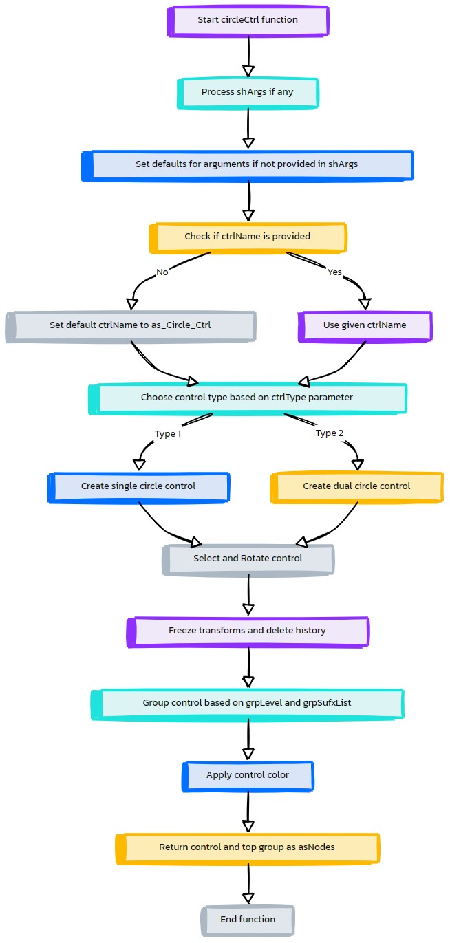
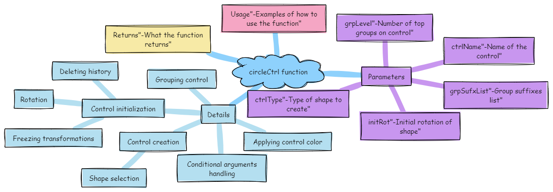
- EasyExp.circleCtrl(self, ctrlName, grpLevel=2, initRot=[0, 0, 0])#
[shArgs : ctrlName=n, grpLevel=gl, initRot=ir, ctrlType=ct, grpSufxList=gsl]
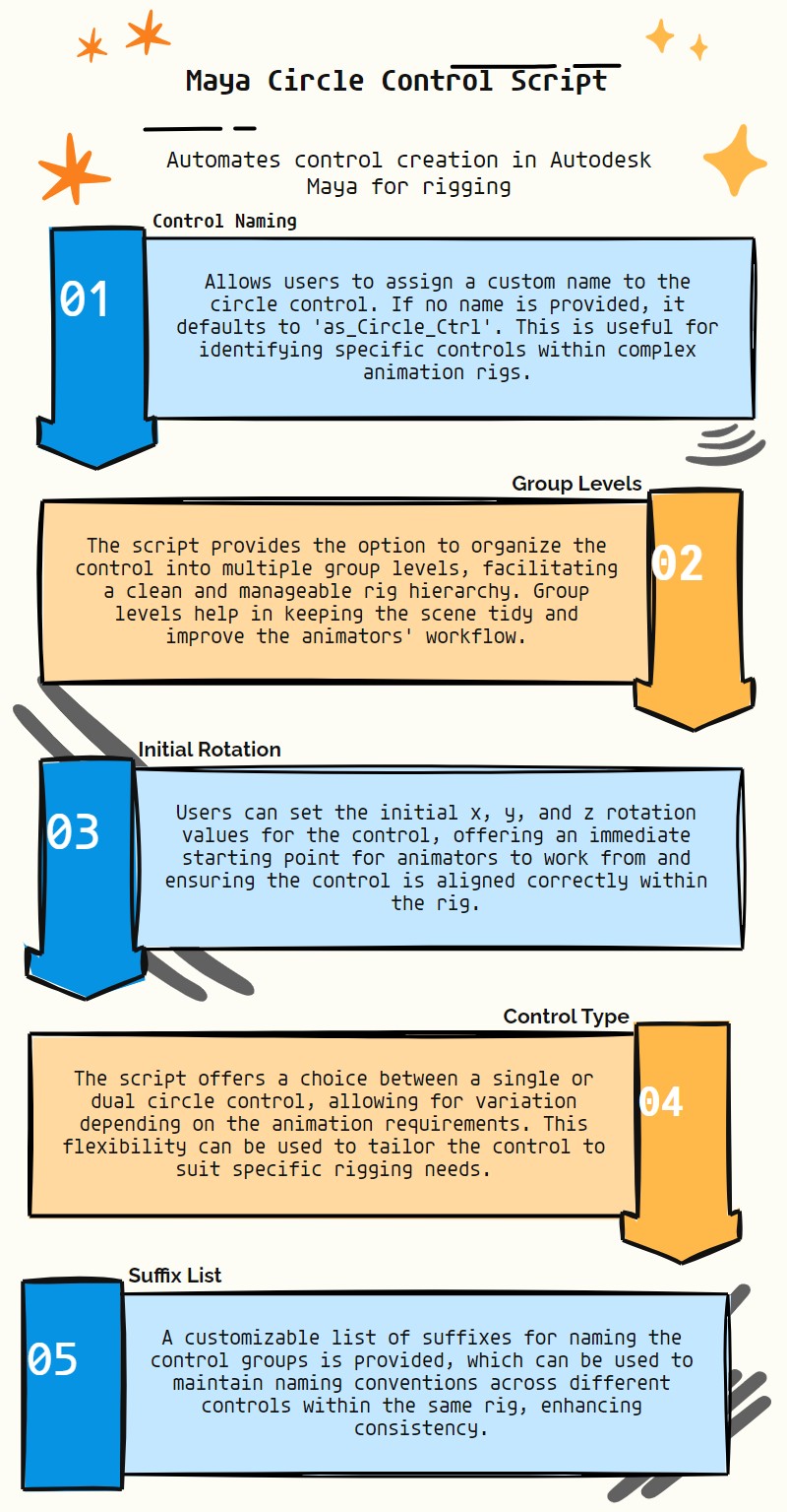
Purpose:
:: Efficiently generates a circular control in Autodesk Maya, ideal for rigging and animation purposes.
The circle control serves as a versatile rigging element for various animation needs, providing intuitive manipulation for animators.
Customizable rotation, group levels, and multiple shape options enhance the utility and adaptability of the control in a rigging context.
- Parameters:
ctrlName – <str, optional> # Name to assign to the circle control. Defaults to ‘as_Circle_Ctrl’ if None.
grpLevel – <int, optional> # Number of grouping levels for organizing the control in the scene. Default is 2.
initRot – <list> # Initial rotation of the control, specified as [x, y, z].
ctrlType – <int, optional> # Type of circle control, with options 1 for a single circle and 2 for a dual circle. Default is 1.
grpSufxList – <list, optional> # List of suffixes for naming the control groups. Defaults to None.
- Returns:
<list> # A list containing the circle control and its top group as asNodes.
Code Examples:
>>> circle_control = circleCtrl(ctrlName="myCircleCtrl", grpLevel=3, initRot=[45, 0, 0], ctrlType=2)
# Creates a dual circle control named "myCircleCtrl" with specific rotation and group level.
- EasyExp.confirmAction(self, action, raiseErr=False, trueVal='Yes', falseVal='No')#
[shArgs : a=action, e=raiseErr, tv=trueVal, fv=falseVal, eb1=ex1Btn, ea1=ex1Action, eb2=ex2Btn, ea2=ex2Action, eb3=ex3Btn, ea3=ex3Action]
Purpose:
:: Requests the user to confirm an action displayed in a dialog window.
- Parameters:
action – (<str>) # The action to be confirmed.
raiseErr – (<bool, optional>) # Whether to raise an error if the action is confirmed. Default is False.
trueVal – (<str, optional>) # The label for the true button in the confirmation dialog. Default is ‘Yes’.
falseVal – (<str, optional>) # The label for the false button in the confirmation dialog. Default is ‘No’.
ex1Btn – (<str, optional>) # Label for an additional button in the confirmation dialog. Default is None.
ex1Action – (<function, optional>) # Action to perform when the additional button is clicked. Default is None.
ex2Btn – (<str, optional>) # Label for a second additional button in the confirmation dialog. Default is None.
ex2Action – (<function, optional>) # Action to perform when the second additional button is clicked. Default is None.
ex3Btn – (<str, optional>) # Label for a third additional button in the confirmation dialog. Default is None.
ex3Action – (<function, optional>) # Action to perform when the third additional button is clicked. Default is None.
- Returns:
<bool/str/None> # True if the action is confirmed as ‘Yes’, False if confirmed as ‘No’, the label of the additional button if clicked, or None if no action is taken.
Code Examples:
>>> confirmation = confirmAction('Are you sure?', trueVal='Confirm', falseVal='Cancel')
>>> if confirmation:
...     print("Action confirmed.")
... else:
...     print("Action canceled.")
graph TD Start[("fa:fa-play Start")] --> CheckShArgs{"/fas:fa-question-circle Check shArgs"} CheckShArgs --"If shArgs Exist"--> ParseShArgs["/fas:fa-cogs Parse shArgs"] CheckShArgs --"If shArgs Does Not Exist"--> InitializeParameters["/fas:fa-wrench Initialize Parameters"] ParseShArgs --> ProcessDialog{"/fas:fa-tasks Process Dialog"} ProcessDialog --> End["/fas:fa-stop End"] style Start fill:#00cc00,stroke:#000,stroke-width:3px style CheckShArgs fill:#ffcc00,stroke:#000,stroke-width:2px style ParseShArgs fill:#ff9999,stroke:#000,stroke-width:2px style InitializeParameters fill:#ff9999,stroke:#000,stroke-width:2px style ProcessDialog fill:#99ccff,stroke:#000,stroke-width:2px style End fill:#ff6666,stroke:#000,stroke-width:3px- Flow Chart Description:
This flowchart illustrates the confirmAction function:
Checks if shArgs exist, and if so, parses the parameters from it.
If shArgs do not exist, initializes parameters with default values.
Processes the dialog window based on the provided parameters.
Ends the process.
- EasyExp.createNode_MD(self, valOrAttr01, valOrAttr02, mdnSign='*', mdnName='asNode_MDN', destAttr=None)#
[shArgs : va1=valOrAttr01, va2=valOrAttr02, ms=mdnSign, mn=mdName, da=destAttr]
Purpose:
:: Creates a ‘multiplyDivide’ node to perform mathematical operations on two input values or attributes.
Performs multiplication, division, or power operations on the inputs.
Useful for procedural rigging, animation setups, and dynamic attribute control.
- Parameters:
valOrAttr01 – <str/float> #First value or attribute for the operation.
valOrAttr02 – <str/float> #Second value or attribute for the operation.
mdnSign – <str> #Operation type: ‘*’ for multiply, ‘/’ for divide, ‘**’ for power.
mdName – <str, optional> #Name for the multiplyDivide node. Defaults to ‘asNode_MD’.
destAttr – <str, optional> #Destination attribute for the output of the operation.
showError – <int, optional> #Flag to show error if input is not connected.
- Returns:
<list> #List containing the multiplyDivide node and the output attribute.
- Flags:
Available mdnSigns are: [‘*’, ‘/’, ‘**’]
Usage:
valOrAttr01 =selected()[0] + '.tx' | selected()[0] + '.t' | 25 | [0, 2, 10]
valOrAttr02 =selected()[1] + '.ty' | selected()[1] + '.r' | 10 | [0, 2, 10]
destAttr =selected()[1] + '.ty' | selected()[1] + '.r'
eSpec.create_MD(valOrAttr01, valOrAttr02, '*', 'node_MD', destAttr)

Returns:
return [mdNode, outAttr]  #_ outAttr = node + '.' + attr
graph TB Start[("fa:fa-play Start")] --> CheckShArgs{{"/fas:fa-question Check shArgs"}} CheckShArgs --"If shArgs is provided" --> UpdateInputs["/fas:fa-exchange-alt Update Inputs"] CheckShArgs --"If shArgs is not provided" --> CreateMDNode["/fas:fa-code-branch Create MD Node"] UpdateInputs --> CreateMDNode CreateMDNode --> SetMdnSign{"/fas:fa-question Set mdnSign"} SetMdnSign --"Set mdnSign operation"--> CheckValOrAttr01{"/fas:fa-question Check valOrAttr01"} CheckValOrAttr01 --"If valOrAttr01 is provided" --> ConnectValOrAttr01["/fas:fa-link Connect valOrAttr01"] ConnectValOrAttr01 --> CheckValOrAttr02{"/fas:fa-question Check valOrAttr02"} CheckValOrAttr01 --"If valOrAttr01 is not provided" --> CheckValOrAttr02 CheckValOrAttr02 --"If valOrAttr02 is provided" --> ConnectValOrAttr02["/fas:fa-link Connect valOrAttr02"] ConnectValOrAttr02 --> SetOutputConnection["/fas:fa-cogs Set Output Connection"] CheckValOrAttr02 --"If valOrAttr02 is not provided" --> SetOutputConnection SetOutputConnection --> ReturnMD["/fas:fa-arrow-right Return MD Node and Output"] ReturnMD --> End[("fas:fa-stop End")] style Start fill:#00cc00,stroke:#000,stroke-width:3px style CheckShArgs fill:#ffcc00,stroke:#000,stroke-width:2px style UpdateInputs fill:#ff9999,stroke:#000,stroke-width:2px style CreateMDNode fill:#99ccff,stroke:#000,stroke-width:2px style SetMdnSign fill:#cc99ff,stroke:#000,stroke-width:2px style CheckValOrAttr01 fill:#99ff99,stroke:#000,stroke-width:2px style ConnectValOrAttr01 fill:#ffcc99,stroke:#000,stroke-width:2px style CheckValOrAttr02 fill:#ccffcc,stroke:#000,stroke-width:2px style ConnectValOrAttr02 fill:#ff9999,stroke:#000,stroke-width:2px style SetOutputConnection fill:#99ccff,stroke:#000,stroke-width:2px style ReturnMD fill:#cc99ff,stroke:#000,stroke-width:2px style End fill:#ff6666,stroke:#000,stroke-width:3px- Flow Chart Description:
This flowchart illustrates the createNode_MD function:
The function starts by checking if additional arguments (shArgs) are provided and updating the inputs accordingly.
A multiplyDivide (MD) node is created, and its operation type is set based on the mdnSign provided.
The first value or attribute (valOrAttr01) is connected to the MD node’s input1.
The second value or attribute (valOrAttr02) is connected to the MD node’s input2.
The output of the MD node is connected to the specified destination attribute, if provided.
Finally, the function returns the MD node and its output attribute.
- EasyExp.ctrlMaker(self, curvList, ctrlName)#
[shArgs : curvList=cl, ctrlName=n]
Purpose:
:: Creates a control curve by combining multiple specified curves.
This method is useful for creating custom control shapes from multiple curve segments.
- Parameters:
curvList – (<list>) #List of curve segments to be combined into a single control curve.
ctrlName – (<str>) #Name to assign to the newly created control curve.
- Returns:
<asNode> #The newly created control curve as an asNode.
Code Examples:
>>> curvList = [edge1, edge2, edge3]
>>> ctrlName = "customCtrl"
>>> ctrlCurv = ctrlMaker(curvList, ctrlName)
# Creates a control curve named "customCtrl" by combining curves from 'edge1', 'edge2', and 'edge3'.
Fonts:
#_ fontList =['Palatino Linotype', 'Bolide', 'Vectroid', 'Snap ITC', 'Quaint', 'Ravie']
#_ ['Outer Sider BRK', 'ChangChangWoodcut']
#_ textCurves(ch=0, t='ikfk', f= 'Quaint|h-16|w700|c0')
#_ font =fontList[rand.randint(0, 5)]
graph TB Start[("fa:fa-play Start")] --> SelectCurves["/fas:fa-mouse-pointer Select Curves"] SelectCurves --> GroupCurves["/fas:fa-object-group Group Curves"] GroupCurves --> SetPivot["/fas:fa-crop-alt Set Pivot"] SetPivot --> SeparateShapes["/fas:fa-cut Separate Shapes"] SeparateShapes --> RenameShapes["/fas:fa-i-cursor Rename Shapes"] RenameShapes --> DeleteGroup["/fas:fa-trash-alt Delete Group"] DeleteGroup --> CreateMainCurve["/fas:fa-pencil-ruler Create Main Curve"] CreateMainCurve --> SetPivotMain["/fas:fa-crop-alt Set Pivot Main"] SetPivotMain --> ApplyCtrlColors["/fas:fa-palette Apply Control Colors"] ApplyCtrlColors --> End[("fas:fa-stop End")] style Start fill:#00cc00,stroke:#000,stroke-width:3px style SelectCurves fill:#ffcc99,stroke:#000,stroke-width:2px style GroupCurves fill:#99ff99,stroke:#000,stroke-width:2px style SetPivot fill:#99ccff,stroke:#000,stroke-width:2px style SeparateShapes fill:#99ccff,stroke:#000,stroke-width:2px style RenameShapes fill:#99ccff,stroke:#000,stroke-width:2px style DeleteGroup fill:#ff9999,stroke:#000,stroke-width:2px style CreateMainCurve fill:#99ccff,stroke:#000,stroke-width:2px style SetPivotMain fill:#99ccff,stroke:#000,stroke-width:2px style ApplyCtrlColors fill:#ffcc99,stroke:#000,stroke-width:2px style End fill:#ff6666,stroke:#000,stroke-width:3px- Flow Chart Description:
This flowchart illustrates the ctrlMaker function:
Starts by selecting curves to form the control.
Groups the selected curves together.
Sets the pivot to the origin for the group.
Separates the shapes from the group.
Renames the separated shapes for clarity.
Deletes the initial group after separation.
Creates a main curve to combine the shapes.
Sets the pivot for the main curve.
Applies control colors based on the naming convention (L_, R_, or default).
- EasyExp.dimondCtrl(self, ctrlName=None, grpLevel=3, initRot=[0, 0, 0], ctrlType=1, grpSufxList=None, **shortArgs)#
[shArgs : ctrlName=n, grpLevel=gl, initRot=ir, ctrlType=ct, grpSufxList=gsl]
Purpose:
:: Creates a diamond-shaped control with optional grouping levels and initial rotation settings.
This method is useful for creating custom controls in rigging setups.
Offers flexibility in control shape, initial rotation, and hierarchy depth.
Argument | Description :param ctrlName: (<str>, optional) # Name for the control to be created. Defaults to ‘as_Dimond_Ctrl’. :param grpLevel: (<int>, optional) # Number of top groups to be created for the control. Defaults to 3. :param initRot: (<list of float>, optional) # List specifying initial rotation in degrees for each axis. :param ctrlType: (<int>, optional) # Specifies the type of control shape. Can be 1, 2, 3, etc. :param grpSufxList: (<list of str>, optional) # List of suffixes for group names, if required.
- Returns:
<list of asNode> # Returns a list containing the created control and its top group node.
Code Examples:
>>> ctrl, ctrlGrp = as_EasyExpMain().dimondCtrl(ctrlName='myControl', grpLevel=2, initRot=[90, 0, 0], ctrlType=1)
# Creates a diamond control named 'myControl' with 2 group levels and initial rotation of 90 degrees on the X-axis.
Args:
ctrlName : name(str)                    #_ name for the control which is going to be created
grpLevl : num(int)                              #_ Number of top groups on control to be created
initRot : [float, float, float] #_ Rotates the shape initially
ctrlType : 1|2|3 etc                    #_ One of 3 Shapes can be returned
graph TB Start[("fa:fa-play Start")] --> CheckArguments{{"/fas:fa-question-circle Check Arguments"}} CheckArguments --"If additional keyword arguments provided" --> UpdateArguments[("/fas:fa-sync Update Arguments")] CheckArguments --"No additional arguments" --> CheckCtrlName{{"/fas:fa-i-cursor Check Control Name"}} UpdateArguments --> CheckCtrlName CheckCtrlName --"If ctrlName is not provided" --> SetDefaultName["/fas:fa-tag Set Default Name"] CheckCtrlName --"If ctrlName is provided" --> SelectCtrlType{{"/fas:fa-shapes Select Control Type"}} SetDefaultName --> SelectCtrlType SelectCtrlType --"Type 1" --> CreateDiamondType1[("/fas:fa-draw-polygon Create Diamond Control Type 1")] SelectCtrlType --"Type 2" --> CreateDiamondType2[("/fas:fa-draw-polygon Create Diamond Control Type 2")] SelectCtrlType --"Type 3" --> CreateDiamondType3[("/fas:fa-draw-polygon Create Diamond Control Type 3")] CreateDiamondType1 --> RotateAndFreeze[("/fas:fa-redo-alt Rotate and Freeze Transform")] CreateDiamondType2 --> RotateAndFreeze CreateDiamondType3 --> RotateAndFreeze RotateAndFreeze --> GroupControl[("/fas:fa-object-group Group Control")] GroupControl --> ApplyCtrlColor[("/fas:fa-palette Apply Control Color")] ApplyCtrlColor --> End[("fas:fa-stop End")] style Start fill:#00cc00,stroke:#000,stroke-width:3px style CheckArguments fill:#ffcc00,stroke:#000,stroke-width:2px style UpdateArguments fill:#99ccff,stroke:#000,stroke-width:2px style CheckCtrlName fill:#cc99ff,stroke:#000,stroke-width:2px style SetDefaultName fill:#ffcc99,stroke:#000,stroke-width:2px style SelectCtrlType fill:#99ff99,stroke:#000,stroke-width:2px style CreateDiamondType1 fill:#ff9999,stroke:#000,stroke-width:2px style CreateDiamondType2 fill:#ccffcc,stroke:#000,stroke-width:2px style CreateDiamondType3 fill:#ffcc00,stroke:#000,stroke-width:2px style RotateAndFreeze fill:#99ccff,stroke:#000,stroke-width:2px style GroupControl fill:#ff6666,stroke:#000,stroke-width:2px style ApplyCtrlColor fill:#ffcc00,stroke:#000,stroke-width:2px style End fill:#ff6666,stroke:#000,stroke-width:3px- Flow Chart Description:
This flowchart illustrates the dimondCtrl function:
Starts by checking if additional keyword arguments are provided and updates arguments accordingly.
Checks if a control name is provided. If not, sets a default name for the control.
Selects the control type based on the ctrlType parameter.
Creates the diamond control based on the selected type (Type 1, 2, or 3).
Rotates and freezes the control’s transformations as per the initRot parameter.
Groups the control according to the specified grpLevel and optionally applies group suffixes.
Applies a control color to the diamond control.
Completes the process and returns the control and its top group.
- EasyExp.doBindSkin(self, jntList, skinMesh, clustName='skinCluster1', ignoreHI=False, skinMethod=2, normalizeMethod=1, maxInflu=3, retainMaxInflu=True, dropRate=8.5)#
[shArgs : jl=jntList, sm=skinMesh, cn=clustName, ih=ignoreHI, sm=skinMethod, mi=maxInflu, dr=dropRate, cre=curvRigidEnds]
Purpose:
:: Applies skinning to a mesh or curve using specified joints, with various skinning methods and options.
This function is used for skinning meshes or curves to joints, providing control over skinning methods, influence limits, and more.
It supports classical linear, dual quaternion, and blended skinning methods.
skinCluster(n=’clustName’, tsb=True, ih=False, sm=2, nw=1, mi=3, omi=1, dr=8.5, rui=0, ps=1, sw=1)
bindMethod : ignoreHI - Disregard the place of joints hierarchy when computing the closest joints that influence a point of the geometry.
skinMethod : 0 - Classical linear skinning (default). 1 - Dual quaternion (volume preserving), 2 - A weighted blend between the two.
Other Args:
nw : 0 - None, 1 - Interactive, 2 - Post (default) for normalizing weights
- Parameters:
jntList – <list, optional> #List of joints to use for skinning. If not provided, uses selected joints.
skinMesh – <str/object, optional> #The mesh or curve to be skinned. If not provided, uses the selected mesh or curve.
clustName – <str, optional> #Name for the created skin cluster. Default is ‘skinCluster1’.
ignoreHI – <int> #Flag to ignore joint hierarchy in skinning calculations.
skinMethod – <int> #Skinning method: 0 (linear), 1 (dual quaternion), or 2 (blend).
maxInflu – <int> #Maximum number of joint influences per vertex.
dropRate – <float> #Dropoff rate for skinning weights.
curvRigidEnds – <list, optional> #Flags to apply rigid skinning at the ends of a curve.
- Returns:
<list> #A list containing the created skin cluster and associated joints.
Code Examples:
>>> doBindSkin(jntList=['joint1', 'joint2'], skinMesh='mesh1', clustName='mySkinCluster', ignoreHI=0, skinMethod=2, maxInflu=3, dropRate=8.5, curvRigidEnds=[1, 1])
graph TB Start[("fa:fa-play Start")] --> CheckArgs{{"/fas:fa-question Check Args"}} CheckArgs --"If jntList and skinMesh are not provided"--> SelectObjects["/fas:fa-mouse-pointer Select Objects"] CheckArgs --"If jntList and skinMesh are provided"--> PrepareSkinList["/fas:fa-cogs Prepare Skin List"] SelectObjects --> PrepareSkinList PrepareSkinList --> IterateSkinMesh{{"/fas:fa-sync-alt Iterate Through Skin Mesh"}} IterateSkinMesh --"For Each Skin Mesh"--> CheckMeshType["/fas:fa-check-square Check Mesh Type"] CheckMeshType --"If Mesh or Curve"--> DeleteExistingSkinCluster["/fas:fa-trash Delete Existing Skin Cluster"] DeleteExistingSkinCluster --> CheckSkinMethod["/fas:fa-search-plus Check Skin Method"] CheckSkinMethod --> DoSkinning["/fas:fa-user-md Do Skinning"] DoSkinning --> CheckIfCurve["/fas:fa-question-circle Check If Curve"] CheckIfCurve --"If Curve"--> AutoWeightCurve["/fas:fa-balance-scale Auto Weight Curve"] AutoWeightCurve --> AddToResultList["/fas:fa-plus-circle Add To Result List"] CheckIfCurve --"Not Curve"--> AddToResultList AddToResultList --> IterateSkinMesh IterateSkinMesh --"All Meshes Processed"--> End[("fas:fa-stop End")] style Start fill:#00cc00,stroke:#000,stroke-width:3px style CheckArgs fill:#ffcc00,stroke:#000,stroke-width:2px style SelectObjects fill:#ff9999,stroke:#000,stroke-width:2px style PrepareSkinList fill:#99ccff,stroke:#000,stroke-width:2px style IterateSkinMesh fill:#cc99ff,stroke:#000,stroke-width:2px style CheckMeshType fill:#99ff99,stroke:#000,stroke-width:2px style DeleteExistingSkinCluster fill:#ffcc99,stroke:#000,stroke-width:2px style CheckSkinMethod fill:#ccffcc,stroke:#000,stroke-width:2px style DoSkinning fill:#ff9999,stroke:#000,stroke-width:2px style CheckIfCurve fill:#99ccff,stroke:#000,stroke-width:2px style AutoWeightCurve fill:#cc99ff,stroke:#000,stroke-width:2px style AddToResultList fill:#99ff99,stroke:#000,stroke-width:2px style End fill:#ff6666,stroke:#000,stroke-width:3px- Flow Chart Description:
This flowchart illustrates the doBindSkin function:
The process begins by checking if joint list and skin mesh are provided; if not, objects are selected interactively.
Prepares a list of skin meshes based on the input or selected objects.
Iterates through each skin mesh to process.
For each skin mesh, checks if it is a mesh or curve and deletes any existing skin cluster.
Verifies the skinning method to ensure it’s valid.
Performs skinning using the specified method, joints, and additional parameters.
If the skin mesh is a curve, auto weights the curve based on the joints.
Adds the skinned mesh and associated skin cluster to the result list.
The process repeats for all skin meshes and ends once all have been processed.
- EasyExp.edgeLoopCtrl(self, ctrlName='as_EdgeLoop_Ctrl', closeLoop=1, grpLevel=0, edgeList=None, oneShape=True, curvDegree=3, stepVal=1, offset=0)#
[shArgs : n=ctrlName, cl=closeLoop, gl=grpLevel, el=edgeList, os=oneShape, cd=curvDegree, sv=stepVal, sp=snapPiv, o=offset, mc=multiCtrls]
Purpose:
:: Generates a control based on an edge loop in Autodesk Maya, with various customization options for shape, grouping, and pivot settings.
This function is particularly useful for rigging and animation tasks where edge loop based controls are needed.
Offers flexibility to create single or multiple controls based on edge loops, with adjustable degree, step value, and offset.
- Parameters:
ctrlName – <int/str, optional> # Name for the control to be created. Defaults to 0 if not provided.
closeLoop – <bool, optional> # Specifies whether to close the first and last edges. Defaults to True.
grpLevel – <int, optional> # Hierarchy level for grouping the control. Defaults to 0.
edgeList – <list/str, optional> # List of edges or a single edge to create the control from. If None, selection is used.
oneShape – <bool, optional> # Determines if a single shape or multiple shapes should be created. Defaults to True.
curvDegree – <int, optional> # Degree of the curve for the control. Ranges from 1 to 5. Defaults to 1.
stepVal – <int, optional> # Step value to skip vertices. Defaults to 1 (no skip).
offset – <int, optional> # Offset value for scaling the control. Defaults to 0.
snapPiv – <bool, optional> # If True, snaps group pivot to the control. Defaults to True.
multiCtrls – <bool, optional> # If True, creates multiple controls for each edge in edgeList. Defaults to False.
- Returns:
<list> # A list containing the control and its top group as Maya nodes, based on grpLevel.
Code Examples:
>>> ctrl_name = "myEdgeLoopCtrl"
>>> edge_loop = ["edge1", "edge2", "edge3"]
>>> control, control_group = edgeLoopCtrl(ctrlName=ctrl_name, edgeList=edge_loop, grpLevel=2)
# This will create a control based on the specified edge loop with 2 group levels.
:param ctrlName : name(str) #_ name for the control which is going to be created :param closeLoop : True | False #_ Closes the first and last edges :param grpLevl : num(int) #_ Number of top groups on control to be created :param edgeList : None | strList | str #_ If edgeList is not given, edges are selected from selection
#_ If singe edge is given, edgeLoop will be selected
:param oneShape : True | False #_ If not oneShape, multiple shapes equal to no of edges will be created :param curvDegree : 1|2|3|4|5 #_ Used for the degree of the curve :param stepVal : 1|2|etc #_ Skips number of vertices (stepVal-1), if stepVal is more than 1 :param offset : num(int) #_ Keeps the created ctrl with the offset in scaling :param snapPiv : True | False #_ Snaps Group pivot to ‘edgeLoopCtrl’
graph TB Start[("fa:fa-play Start")] --> CheckCtrlName{{"/fas:fa-keyboard Check Control Name"}} CheckCtrlName --"CtrlName provided"--> CheckEdgeListProvided{{"/fas:fa-list-ol Check Edge List Provided"}} CheckCtrlName --"CtrlName not provided"--> AssignDefaultName[("/fas:fa-edit Assign Default Ctrl Name")] AssignDefaultName --> CheckEdgeListProvided CheckEdgeListProvided --"EdgeList provided"--> CheckMultiCtrls{{"/fas:fa-clone Check Multiple Controls"}} CheckEdgeListProvided --"EdgeList not provided"--> SelectEdgesFromSelection[("/fas:fa-mouse-pointer Select Edges from Selection")] SelectEdgesFromSelection --> CheckMultiCtrls CheckMultiCtrls --"Single Control"--> CreateSingleControl[("/fas:fa-object-group Create Single Control")] CheckMultiCtrls --"Multiple Controls"--> CreateMultipleControls[("/fas:fa-object-ungroup Create Multiple Controls")] CreateSingleControl --> FinalizeCtrl[("/fas:fa-check-square Finalize Control")] CreateMultipleControls --> FinalizeCtrl FinalizeCtrl --> End[("fas:fa-stop-circle End")] style Start fill:#00cc00,stroke:#000,stroke-width:3px style CheckCtrlName fill:#ffcc00,stroke:#000,stroke-width:2px style AssignDefaultName fill:#99ff99,stroke:#000,stroke-width:2px style CheckEdgeListProvided fill:#ffcc00,stroke:#000,stroke-width:2px style SelectEdgesFromSelection fill:#99ccff,stroke:#000,stroke-width:2px style CheckMultiCtrls fill:#ffcc00,stroke:#000,stroke-width:2px style CreateSingleControl fill:#cc99ff,stroke:#000,stroke-width:2px style CreateMultipleControls fill:#cc99ff,stroke:#000,stroke-width:2px style FinalizeCtrl fill:#cc99ff,stroke:#000,stroke-width:2px style End fill:#ff6666,stroke:#000,stroke-width:3px- Flow Chart Description:
This flowchart illustrates the edgeLoopCtrl function:
The function starts by checking if a control name is provided. If not, a default name is assigned.
It then checks if an edge list is provided. If not, edges are selected from the current selection.
The function determines whether to create a single control or multiple controls based on the ‘multiCtrls’ parameter.
For a single control, it creates one control based on the provided edge loop.
For multiple controls, it creates individual controls for each edge in the edge list.
Finally, the function finalizes the control with group levels, pivot snapping, and color application.
The process ends by returning the control and its top group.
- EasyExp.generateCurv(self, curvName, deg=3, step=1, objOrPosList=None)#
[shArgs: n=curvName, d=deg, s=step, opl=objOrPosList, sc=showCVs, se=showEditor, pc=printCommand]
Function:: generateCurv
Purpose:
:: Generates a curve with specified parameters in Maya.
- Parameters:
curvName – (<str>) # Name for the generated curve. Default is ‘as_Curv’.
deg – (<int>) # Degree of the curve. Default is 3.
step – (<int>) # Step value for the curve. Default is 1.
objOrPosList – (<list>) # List of objects or positions to define the curve.
showCVs – (<bool>) # If True, shows the CVs of the curve.
showEditor – (<bool>) # If True, opens the curve editor.
printCommand – (<bool>) # If True, prints the command used to create the curve.
- Returns:
curvNode # asNode
- Usage::
#_ (Usage: Select the vertices or objects not the curve itself)
>>> generateCurv(curvName="myCurve", deg=2, step=2, objOrPosList=["obj1", "obj2", "obj3"], showCVs=True, showEditor=False, printCommand=True)
graph TB style Start fill:#00cc00,stroke:#000,stroke-width:3px style CheckShArgs fill:#ffcc00,stroke:#000,stroke-width:2px style RetrievePositions fill:#ff9999,stroke:#000,stroke-width:2px style ReducePositionList fill:#99ccff,stroke:#000,stroke-width:2px style BuildCurveString fill:#99ff99,stroke:#000,stroke-width:2px style ExecuteCurveCommand fill:#99ff99,stroke:#000,stroke-width:2px style ShowCVs fill:#99ff99,stroke:#000,stroke-width:2px style ShowEditor fill:#99ff99,stroke:#000,stroke-width:2px style PrintCommand fill:#99ff99,stroke:#000,stroke-width:2px style ReturnCurveNode fill:#99ff99,stroke:#000,stroke-width:2px style End fill:#ff6666,stroke:#000,stroke-width:3px Start[("fa:fa-play Start")] --> CheckShArgs{"/fas:fa-question-circle Check shArgs"} CheckShArgs --"If shArgs provided"--> RetrievePositions["/fas:fa-object-group Retrieve Positions"] CheckShArgs --"If shArgs not provided"--> RetrievePositions RetrievePositions --> ReducePositionList["/fas:fa-compress-arrows-alt Reduce Position List"] ReducePositionList --> BuildCurveString["/fas:fa-pencil-ruler Build Curve String"] BuildCurveString --> ExecuteCurveCommand["/fas:fa-play-circle Execute Curve Command"] ExecuteCurveCommand --> ShowCVs{"/fas:fa-eye Show CVs"} ShowCVs --"If True"--> ShowEditor{"/fas:fa-edit Show Editor"} ShowCVs --"If False"--> PrintCommand{"/fas:fa-print Print Command"} ShowEditor --"If True"--> PrintCommand ShowEditor --"If False"--> PrintCommand PrintCommand --"If True"--> ReturnCurveNode["/fas:fa-curve Return Curve Node"] PrintCommand --"If False"--> ReturnCurveNode ReturnCurveNode --> End[("fas:fa-stop End")]- Flow Chart Description:
This flowchart illustrates the generateCurv function:
The process starts by checking if shArgs are provided, updating parameters accordingly.
It retrieves the positions from the objects or positions list.
The position list is reduced based on the step value.
A curve creation command string is built using the positions and curve parameters.
The curve command is executed to generate the curve.
If showCVs is True, the Curve Vertices (CVs) are displayed.
If showEditor is True, the curve editor is shown.
If printCommand is True, the curve creation command is printed.
The function concludes by returning the created curve node.
- EasyExp.generateLipsCurve(self)#
[**shArgs : ]
Purpose:
:: Generates a lips curve based on selected edges or rebuilds the provided curve.
- Returns:
(<NoneType>) # This function does not return anything.
Code Examples:
>>> generateLipsCurve()
graph TB Start[("fa:fa-play Start")] --> CheckRebuildCheckbox{"/fas:fa-check-square Check Rebuild Checkbox"} CheckRebuildCheckbox --"If Rebuild Checkbox Not Checked and Selected Object is Not Curve"--> CheckEdgeList["/fas:fa-question-circle Check Edge List"] CheckRebuildCheckbox --"If Rebuild Checkbox Not Checked and Selected Object is Not Curve"--> End["/fas:fa-stop End"] CheckEdgeList --"If Edge List Not Empty"--> CheckEdgeCount["/fas:fa-question-circle Check Edge Count"] CheckEdgeList --"If Edge List Empty"--> ShowErrorMessage["/fas:fa-exclamation-triangle Show Error Message"] CheckEdgeCount --"If Edge Count Equals 1"--> SetCloseCurveCheckbox["/fas:fa-check-square Set Close Curve Checkbox"] CheckEdgeCount --"If Edge Count Not Equals 1"--> ShowErrorMessage SetCloseCurveCheckbox --> GetCloseLoopValue["/fas:fa-arrow-right Get Close Loop Value"] GetCloseLoopValue --> SetCurveName["/fas:fa-arrow-right Set Curve Name"] SetCurveName --> CreateCurve["/fas:fa-bullseye Create Curve"] CreateCurve --> RebuildCurve["/fas:fa-retweet Rebuild Curve"] RebuildCurve --> End style Start fill:#00cc00,stroke:#000,stroke-width:3px style CheckRebuildCheckbox fill:#ffcc00,stroke:#000,stroke-width:2px style CheckEdgeList fill:#99ff99,stroke:#000,stroke-width:2px style CheckEdgeCount fill:#99ff99,stroke:#000,stroke-width:2px style ShowErrorMessage fill:#ff9999,stroke:#000,stroke-width:2px style SetCloseCurveCheckbox fill:#99ff99,stroke:#000,stroke-width:2px style GetCloseLoopValue fill:#ffcc99,stroke:#000,stroke-width:2px style SetCurveName fill:#ccffcc,stroke:#000,stroke-width:2px style CreateCurve fill:#ff9999,stroke:#000,stroke-width:2px style RebuildCurve fill:#ff9999,stroke:#000,stroke-width:2px style End fill:#ff6666,stroke:#000,stroke-width:3px- Flow Chart Description:
This flowchart illustrates the generateLipsCurve function:
Checks if the ‘RebuildCurv’ checkbox is not checked and the selected object is not a curve.
- If the checkbox is not checked and the selected object is not a curve:
Checks if an edge list is empty.
If the edge list is not empty, checks the count of edges.
If the count of edges equals 1, sets the ‘CloseCurve’ checkbox.
Obtains the value of the ‘CloseCurve’ checkbox.
Sets the curve name based on whether the upper or lower lip curve exists.
Creates the curve.
Rebuilds the curve.
The function concludes.
- EasyExp.generate_HyperSkin(self, jntList=None, vtxList=None, bodyMesh=None)#
[shArgs : ]
Purpose:
:: Generates a hyper skinning setup for enhanced skin deformation on a character or object in Autodesk Maya.
Facilitates precise skinning by allowing targeted influence of joints on specific vertices of a mesh.
Enhances the deformation quality around joints, providing more realistic movements for characters or objects.
Operates on the selected mesh and joint list, automatically identifying nearest vertices for skinning influence.
Offers an option to specify vertices and joints manually for more controlled skinning.
- Parameters:
jntList – <list> #List of joints to influence the skinning.
vtxList – <list> #List of vertices to be influenced by the specified joints.
bodyMesh – <str> #Name of the body mesh to which the hyper skinning is applied.
Usage Example:
>>> generate_HyperSkin(jntList, vtxList, 'bodyMesh')
# Applies hyper skinning to 'bodyMesh' using the specified joints and vertices for enhanced deformation.
Note: - If ‘vtxList’ is not provided, the tool will automatically determine the nearest vertices for each joint. - The skin cluster of ‘bodyMesh’ should exist before using this function.
graph TB Start[("fa:fa-play Start")] --> CheckVertexList{"/fas:fa-check-square Check Vertex List"} CheckVertexList --"If Vertex List is Provided"--> UseProvidedVertices["/fas:fa-hand-point-right Use Provided Vertices"] CheckVertexList --"If Vertex List is Not Provided"--> GetBodyMesh["/fas:fa-tshirt Get Body Mesh"] GetBodyMesh --> CheckMeshType{"/fas:fa-question-circle Check Mesh Type"} CheckMeshType --"If Mesh is Not Skinned"--> ErrorMeshNotSkinned["/fas:fa-exclamation-triangle Error: Mesh Not Skinned"] CheckMeshType --"If Mesh is Skinned"--> CheckJointList{"/fas:fa-question-circle Check Joint List"} CheckJointList --"If Joint List Provided"--> UseProvidedJoints["/fas:fa-hand-point-right Use Provided Joints"] CheckJointList --"If Joint List Not Provided"--> ErrorNoJointsProvided["/fas:fa-exclamation-triangle Error: No Joints Provided"] UseProvidedVertices --> ApplyHyperSkinning["/fas:fa-syringe Apply Hyper Skinning"] UseProvidedJoints --> ApplyHyperSkinning ApplyHyperSkinning --"Perform Hyper Skinning Process"--> End[("fas:fa-stop End")] ErrorMeshNotSkinned --> End ErrorNoJointsProvided --> End style Start fill:#00cc00,stroke:#000,stroke-width:3px style CheckVertexList fill:#ffcc00,stroke:#000,stroke-width:2px style UseProvidedVertices fill:#99ccff,stroke:#000,stroke-width:2px style GetBodyMesh fill:#99ccff,stroke:#000,stroke-width:2px style CheckMeshType fill:#ff9999,stroke:#000,stroke-width:2px style ErrorMeshNotSkinned fill:#ff6666,stroke:#000,stroke-width:2px style CheckJointList fill:#ffcc00,stroke:#000,stroke-width:2px style UseProvidedJoints fill:#99ccff,stroke:#000,stroke-width:2px style ErrorNoJointsProvided fill:#ff6666,stroke:#000,stroke-width:2px style ApplyHyperSkinning fill:#5cb85c,stroke:#000,stroke-width:2px style End fill:#ff6666,stroke:#000,stroke-width:3px- Flow Chart Description:
This flowchart illustrates the generate_HyperSkin function:
Starts by checking if a vertex list is provided.
If provided, uses these vertices for skinning influence. If not, it retrieves the body mesh to be skinned.
Checks if the body mesh is already skinned. If not, raises an error.
Checks if a joint list is provided for influencing the skin.
If the joint list is provided, uses these joints. If not, raises an error for no joints provided.
Applies the hyper skinning process to enhance skin deformation around joints.
The process ends once hyper skinning is successfully applied or an error is encountered.
- EasyExp.getClosestParam_Crv(self, from_ObjOrPos, curvName, getLoc=True)#
[shArgs : fo=from_ObjOrPos, cn=curvName, gl=getLoc]
Purpose:
:: Retrieves the parameter value on a curve that is closest to a given object or position in Autodesk Maya.
Ideal for rigging and animation tasks where precision placement or movement along curves is required.
- Parameters:
from_ObjOrPos – <asNode/str/list> #Object or position from which to find the closest parameter on the curve.
curvName – <str> #Name of the curve to find the closest parameter on.
getLoc – <bool> #If True, returns a locator at the position of the closest parameter.
- Returns:
<float/asNode> #Parameter value or locator at the position of the closest parameter on the curve.
Code Examples:
>>> getClosestParam_Crv(from_ObjOrPos='pSphere1', curvName='curve1', getLoc=False)
graph TB Start[("fa:fa-play Start")] --> RetrieveCurve["/fas:fa-bezier-curve Retrieve Curve"] RetrieveCurve --> DetermineSourcePosition["/fas:fa-crosshairs Determine Source Position"] DetermineSourcePosition --> GetClosestPositionOnCurve["/fas:fa-route Get Closest Position on Curve"] GetClosestPositionOnCurve --> CalculateParameter["/fas:fa-ruler-combined Calculate Parameter Value"] CalculateParameter --> CreateLocator["/fas:fa-map-marker-alt Create Locator at Position (Optional)"] CreateLocator --> End[("fas:fa-stop End")] CalculateParameter --"If getLoc is False"--> End style Start fill:#00cc00,stroke:#000,stroke-width:3px style RetrieveCurve fill:#ffcc00,stroke:#000,stroke-width:2px style DetermineSourcePosition fill:#ff9999,stroke:#000,stroke-width:2px style GetClosestPositionOnCurve fill:#99ccff,stroke:#000,stroke-width:2px style CalculateParameter fill:#cc99ff,stroke:#000,stroke-width:2px style CreateLocator fill:#99ff99,stroke:#000,stroke-width:2px style End fill:#ff6666,stroke:#000,stroke-width:3px- Flow Chart Description:
This flowchart illustrates the getClosestParam_Crv function:
The process begins by retrieving the curve data from the specified curve (curvName).
It determines the source position from the given object or position (from_ObjOrPos).
The function finds the closest position on the curve to this source position.
It calculates the parameter value on the curve at this closest position.
If getLoc is True, the function creates a locator at this position on the curve.
The process ends by either returning the parameter value or the locator, based on the getLoc argument.
- EasyExp.getClosestPos_Crv(self, from_ObjOrPos, curvName, getLoc=True)#
[shArgs : from_ObjOrPos=fop, curvName=cn, getLoc=gl]
Purpose:
:: Finds the nearest position on a specified curve from a given object or position.
This function is commonly used in rigging and animation to align objects or locators to a curve.
- Parameters:
from_ObjOrPos – (<str/list>) #Source object or position from which to find the nearest point on the curve.
curvName – (<str>) #Name of the curve to calculate the nearest point on.
getLoc – (<bool>, optional) #If True, returns a locator at the nearest point. If False, returns the position coordinates.
- Returns:
If getLoc is True, returns a locator at the nearest point on the curve. If False, returns a list of position coordinates.
Code Examples:
>>> nearest_point_locator = getClosestPos_Crv('Sphere1', 'Curve1', True)
# Returns a locator positioned at the nearest point on 'Curve1' from 'Sphere1'.

>>> nearest_point_position = getClosestPos_Crv([1, 2, 3], 'Curve1', False)
# Returns the coordinates of the nearest point on 'Curve1' from position [1, 2, 3].
graph TB Start[("fa:fa-play Start")] --> GetClosestPosition{{"/fas:fa-map-marker-alt Get Closest Position"}} GetClosestPosition --"Create nearestPointOnCurve node" --> SetInputData["/fas:fa-edit Set Input Data"] SetInputData --> ConnectCurve["/fas:fa-plug Connect Curve"] ConnectCurve --> RetrievePosition{{"/fas:fa-crosshairs Retrieve Position"}} RetrievePosition --> CheckReturnLocator{"/fas:fa-question-circle Check Return Locator"} CheckReturnLocator --"If getLoc is True" --> CreateLocator["/fas:fa-map-marker Create Locator"] CheckReturnLocator --"If getLoc is False" --> ReturnPosition["/fas:fa-arrow-right Return Position"] CreateLocator --> ReturnLocator["/fas:fa-arrow-right Return Locator"] ReturnPosition --> End[("fas:fa-stop End")] ReturnLocator --> End style Start fill:#00cc00,stroke:#000,stroke-width:3px style GetClosestPosition fill:#ffcc00,stroke:#000,stroke-width:2px style SetInputData fill:#99ff99,stroke:#000,stroke-width:2px style ConnectCurve fill:#ff9999,stroke:#000,stroke-width:2px style RetrievePosition fill:#99ccff,stroke:#000,stroke-width:2px style CheckReturnLocator fill:#cc99ff,stroke:#000,stroke-width:2px style CreateLocator fill:#ffcc99,stroke:#000,stroke-width:2px style ReturnPosition fill:#ccffcc,stroke:#000,stroke-width:2px style ReturnLocator fill:#ccccff,stroke:#000,stroke-width:2px style End fill:#ff6666,stroke:#000,stroke-width:3px- Flow Chart Description:
This flowchart illustrates the getClosestPos_Crv function:
The function begins by getting the closest position on the curve to the specified object or position.
It sets the input data for the nearest point calculation.
The curve is connected to the nearestPointOnCurve node.
The position on the curve closest to the given point is retrieved.
The function checks if a locator is required to be returned.
If getLoc is True, a locator is created at the closest position.
The closest position or the created locator is then returned.
- EasyExp.getModelFile(self)#
[shArgs : srcPath=sp, destFile=df]
Purpose:
:: Opens a file dialog to select a Maya model file and updates the specified text field with the selected file path.
This function is particularly useful in user interfaces where users need to select and load model files.
- Parameters:
srcPath – (<str>) #Initial directory path shown in the file dialog.
destFile – (<str>, output) #Path of the selected Maya model file.
- Returns:
None. Updates the ‘as_ModelFile_TF’ text field with the path of the selected file.
Code Examples:
>>> getModelFile()
# Opens a file dialog for selecting a Maya model file and updates the 'as_ModelFile_TF' text field with the selected file path.
graph TB Start[("fa:fa-play Start")] --> GetSrcPath["/fas:fa-folder-open Get Source Path"] GetSrcPath --> OpenDialog["/fas:fa-file-upload Open File Dialog"] OpenDialog --> UpdatePath["/fas:fa-sync Update Path"] UpdatePath --> End[("fas:fa-stop End")] style Start fill:#00cc00,stroke:#000,stroke-width:3px style GetSrcPath fill:#ffcc99,stroke:#000,stroke-width:2px style OpenDialog fill:#99ff99,stroke:#000,stroke-width:2px style UpdatePath fill:#99ccff,stroke:#000,stroke-width:2px style End fill:#ff6666,stroke:#000,stroke-width:3px- Flow Chart Description:
This flowchart illustrates the getModelFile function:
The process begins by retrieving the source path from a text field.
An open file dialog is initiated, allowing the user to select a Maya file.
The chosen file’s path is then updated in the text field.
- EasyExp.isAttr(self, objNAttr)#
[**shArgs : oa=objNAttr]
Purpose:
:: Determines if the specified object attribute exists.
- Parameters:
objNAttr – <str> # The object and attribute in the format ‘object.attribute’.
- Returns:
<bool> # True if the attribute exists on the specified object, False otherwise.
Code Examples:
>>> attr_to_check = "myObject.myAttribute"
>>> result = isAttr(attr_to_check)
# Explain above code in one line
graph TB Start_isAttr[("fa:fa-play Start")] --> CheckFormat_isAttr{{"/fas:fa-question Check Format"}} CheckFormat_isAttr --"If format is 'object.attribute'" --> SplitObjAttr_isAttr["/fas:fa-cut Split Object & Attribute"] CheckFormat_isAttr --"If format is not 'object.attribute'" --> ReturnFalse_isAttr1["/fas:fa-times Return False"] SplitObjAttr_isAttr --> CheckExistence_isAttr{{"/fas:fa-question Check Attribute Existence"}} CheckExistence_isAttr --"If attribute exists" --> ReturnTrue_isAttr["/fas:fa-check Return True"] CheckExistence_isAttr --"If attribute does not exist" --> ReturnFalse_isAttr2["/fas:fa-times Return False"] style Start_isAttr fill:#00cc00,stroke:#000,stroke-width:3px style CheckFormat_isAttr fill:#ffcc00,stroke:#000,stroke-width:2px style SplitObjAttr_isAttr fill:#99ccff,stroke:#000,stroke-width:2px style ReturnFalse_isAttr1 fill:#ff6666,stroke:#000,stroke-width:2px style CheckExistence_isAttr fill:#ffcc00,stroke:#000,stroke-width:2px style ReturnTrue_isAttr fill:#99ff99,stroke:#000,stroke-width:2px style ReturnFalse_isAttr2 fill:#ff6666,stroke:#000,stroke-width:2px- Flow Chart Description:
This flowchart illustrates the isAttr function:
The function starts by checking the format of the input, ensuring it’s in the ‘object.attribute’ format.
If the format is correct, it splits the input into object and attribute components.
The function then checks if the attribute exists on the specified object, returning True if it does and False otherwise.
- EasyExp.isNum(self, obj)#
- EasyExp.locCtrl(self, ctrlName, grpLevel=1)#
[shArgs : cn=ctrlName, gl=grpLevel]
Purpose:
:: Generates a locator-like control in Autodesk Maya, customizable with control name and group level.
- Parameters:
ctrlName – <str> #Name for the locator control.
grpLevel – <int, optional> #Specifies the hierarchy level for grouping the control. Default is 1.
- Returns:
<list> #A list containing the control and its top group as Maya nodes, based on grpLevel.
Usage:
ctrl                  =eCtrl.locCtrl(ctrlName)[0]
ctrlGrp       =eCtrl.locCtrl(ctrlName)[-1]
ctrl, ctrlGrp =eCtrl.locCtrl(ctrlName)
graph TB Start[("fa:fa-play Start")] --> CheckShArgs{"/fas:fa-question-circle Check shArgs"} CheckShArgs --"If shArgs Exist"--> ParseShArgs["/fas:fa-cogs Parse shArgs"] CheckShArgs --"If shArgs Does Not Exist"--> InitializeParameters["/fas:fa-wrench Initialize Parameters"] InitializeParameters --> CreateLocatorControl{"/fas:fa-pen-nib Create Locator Control"} ParseShArgs --"If shArgs Exist"--> CreateLocatorControl CreateLocatorControl --"Create Locator Control"--> CreateControlGroup{"/fas:fa-object-group Create Control Group"} CreateControlGroup --"Create Control Group"--> ApplyControlColor["/fas:fa-paint-brush Apply Control Color"] ApplyControlColor --"Apply Control Color"--> End["/fas:fa-stop End"] style Start fill:#00cc00,stroke:#000,stroke-width:3px style CheckShArgs fill:#ffcc00,stroke:#000,stroke-width:2px style ParseShArgs fill:#ff9999,stroke:#000,stroke-width:2px style InitializeParameters fill:#99ccff,stroke:#000,stroke-width:2px style CreateLocatorControl fill:#ccffcc,stroke:#000,stroke-width:2px style CreateControlGroup fill:#99ccff,stroke:#000,stroke-width:2px style ApplyControlColor fill:#ffcc99,stroke:#000,stroke-width:2px style End fill:#ff6666,stroke:#000,stroke-width:3px- Flow Chart Description:
This flowchart illustrates the locCtrl function:
Checks if shArgs exist and parses them if present.
Initializes parameters for control creation, including ctrlName and grpLevel.
Creates a locator-like control using the provided ctrlName.
Creates a control group based on the grpLevel.
Applies control color to the control.
- EasyExp.message(self, messageTxt)#
[**shArgs : mt=messageTxt]
Purpose:
:: Sends a given message through confirmDialog window.
Provide Argument | Description:
- Parameters:
messageTxt – (<str>) # The message to be displayed in the dialog window.
- Returns:
(<NoneType>) # No return value.
Code Examples:
>>> message("This is a sample message!")
graph TB Start[("fa:fa-play Start")] --> CheckShArgs{{"/fas:fa-question Check shArgs"}} CheckShArgs --"If shArgs is provided"--> ProcessShArgs["/fas:fa-cogs Process shArgs"] CheckShArgs --"If shArgs is not provided"--> CallConfirmDialog["/fas:fa-comment-dots Call confirmDialog"] ProcessShArgs --> CallConfirmDialog CallConfirmDialog --"Display message in dialog"--> End[("fas:fa-stop End")] style Start fill:#00cc00,stroke:#000,stroke-width:3px style CheckShArgs fill:#ffcc00,stroke:#000,stroke-width:2px style ProcessShArgs fill:#ff9999,stroke:#000,stroke-width:2px style CallConfirmDialog fill:#99ccff,stroke:#000,stroke-width:2px style End fill:#ff6666,stroke:#000,stroke-width:3px- Flow Chart Description:
This flowchart illustrates the message function:
The process starts by checking if shArgs are provided and updates messageTxt if necessary.
It then calls the confirmDialog function to display the message.
- EasyExp.old_generate_HyperSkin(self, jntList=None)#
- EasyExp.old_setScale(self, ctrlGrpList, refObj=None, refAttr=None, ratio=1.0, refVal=None)#
- EasyExp.rebuildCurv(self, curvName=None)#
[**shArgs : c=curvName]
Purpose:
:: Rebuilds a curve with specified parameters.
- Parameters:
curvName – (<str>) # Optional. The name of the curve to be rebuilt. If not provided, the selected curve will be rebuilt.
- Returns:
(<str> or <NoneType>) # Returns the name of the rebuilt curve if successful, otherwise None.
Code Examples:
>>> rebuildCurv(curvName="myCurve")
>>> rebuildCurv()
graph TB Start[("fa:fa-play Start")] --> CheckCurvName{"/fas:fa-question-circle Check CurvName"} CheckCurvName --"If CurvName is None"--> SelectCurv["/fas:fa-mouse-pointer Select Curv"] CheckCurvName --"If CurvName is Specified"--> GetCurvFromName["/fas:fa-arrow-right Get Curv From Name"] SelectCurv --> CheckSelectedCurv{"/fas:fa-check-square Check Selected Curv"} CheckSelectedCurv --"If Curv is Selected"--> GetSelectedCurv["/fas:fa-check-square Get Selected Curv"] CheckSelectedCurv --"If Curv is Not Selected"--> End["/fas:fa-stop End"] GetCurvFromName --> CheckCurvExists{"/fas:fa-question-circle Check Curv Exists"} CheckCurvExists --"If Curv Exists"--> GetCurvShape["/fas:fa-arrow-right Get Curv Shape"] CheckCurvExists --"If Curv Does Not Exist"--> End GetSelectedCurv --> GetCurvShape GetCurvShape --> GetCurvDegree["/fas:fa-ruler-horizontal Get Curv Degree"] GetCurvDegree --> GetNumSpans["/fas:fa-arrows-alt Get Num Spans"] GetNumSpans --> RebuildCurve["/fas:fa-retweet Rebuild Curve"] RebuildCurve --> End["/fas:fa-stop End"] style Start fill:#00cc00,stroke:#000,stroke-width:3px style CheckCurvName fill:#ffcc00,stroke:#000,stroke-width:2px style SelectCurv fill:#ff9999,stroke:#000,stroke-width:2px style GetCurvFromName fill:#99ccff,stroke:#000,stroke-width:2px style CheckSelectedCurv fill:#cc99ff,stroke:#000,stroke-width:2px style End fill:#ff6666,stroke:#000,stroke-width:3px style CheckCurvExists fill:#99ff99,stroke:#000,stroke-width:2px style GetCurvShape fill:#ffcc99,stroke:#000,stroke-width:2px style GetCurvDegree fill:#ccffcc,stroke:#000,stroke-width:2px style GetNumSpans fill:#99ccff,stroke:#000,stroke-width:2px style RebuildCurve fill:#ff9999,stroke:#000,stroke-width:2px- Flow Chart Description:
This flowchart illustrates the rebuildCurv function:
Checks if the curvName parameter is None.
If curvName is None, selects the curve interactively.
If curvName is specified, gets the curve from the given name.
- If the curve is selected or obtained from the name:
Checks if the curve exists.
If the curve exists, gets its shape.
Retrieves the degree of the curve.
Gets the number of spans of the curve.
Rebuilds the curve with the specified parameters.
The function concludes.
- EasyExp.refreshView(self, num)#
- EasyExp.setScale(self, ctrlList=None, refObj=None, refAttr=None, ratio=1.0, refVal=None, **shortArgs)#
[**shArgs : cl=ctrlList, ro=refObj, ra=refAttr, r=ratio, rv=refVal, fi=freezeIt, us=useShape]
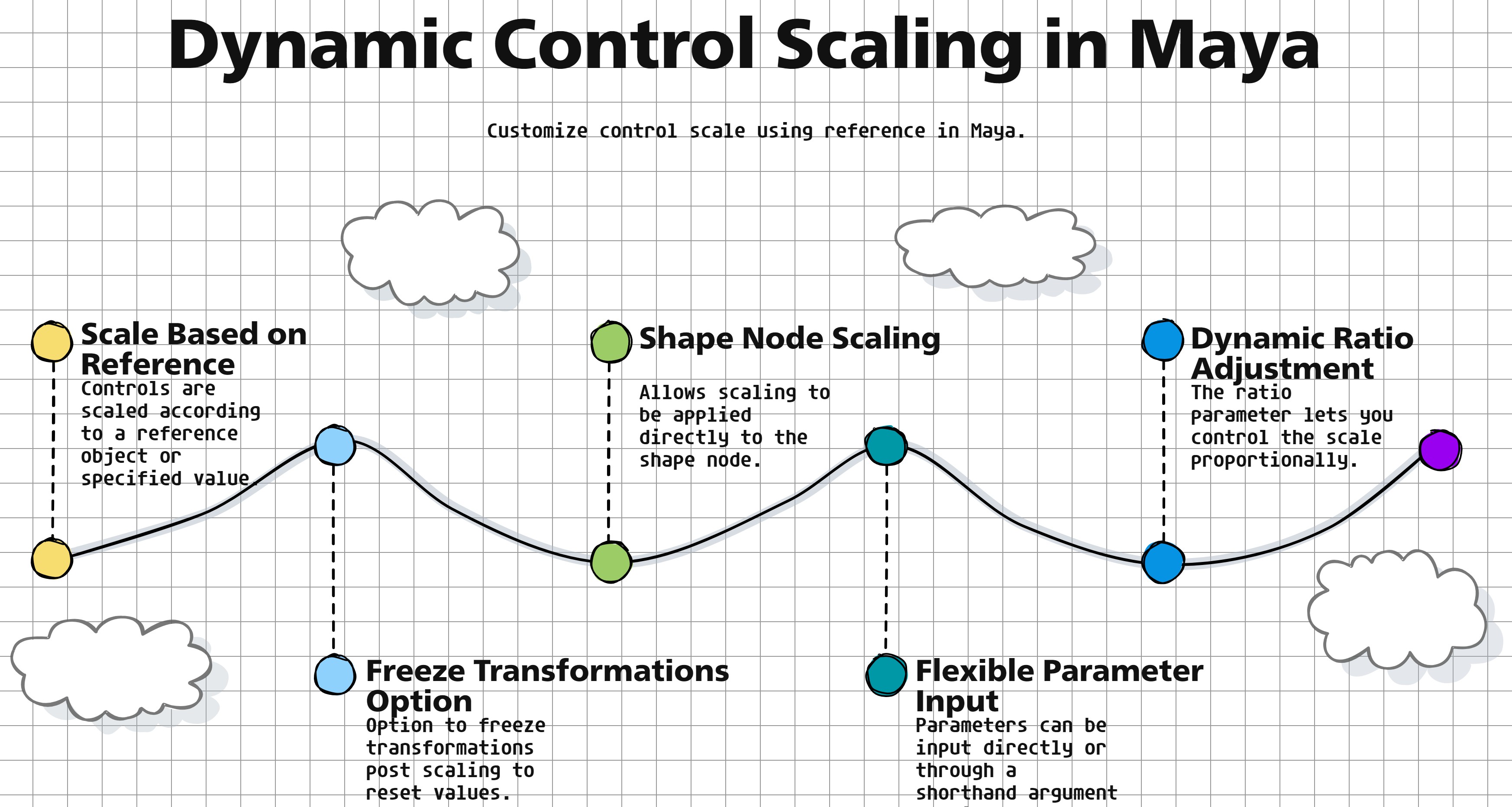
Purpose:
:: Adjusts the scale of a list of controls in Autodesk Maya based on a reference object or value.
Useful for dynamically scaling controls in relation to another object’s attributes or a specified value.
Offers options to freeze transformations and use shape nodes for scaling.
- Parameters:
ctrlList – <list, optional> # List of control names to be scaled. If None, uses the currently selected controls.
refObj – <str, optional> # Name of the reference object for scaling.
refAttr – <str, optional> # Name of the attribute on the reference object to use for scaling.
ratio – <float> # Ratio to apply to the reference attribute value for scaling.
refVal – <float, optional> # Direct reference value to use for scaling if no reference object is specified.
freezeIt – <bool> # Whether to freeze transformations after scaling.
useShape – <bool> # Whether to apply scaling to the shape node instead of the transform node.
- Returns:
None # Does not return a value but scales the specified controls.
Code Examples:
>>> control_list = ["ctrl1", "ctrl2"]
>>> reference_object = "locator1"
>>> scale_ratio = 1.5
>>> setScale(control_list, reference_object, ratio=scale_ratio)
# Scales the controls in control_list based on the scale of reference_object with a ratio of 1.5.
graph TB Start[("fa:fa-play Start")] --> CheckInputs{"/fas:fa-question-circle Check Inputs"} CheckInputs --"If ctrlList is provided"--> DetermineScaling[("/fas:fa-search Determine Scaling")] CheckInputs --"If ctrlList is not provided"--> SelectControls{"/fas:fa-mouse-pointer Select Controls"} SelectControls --"Controls selected"--> DetermineScaling SelectControls --"No controls selected"--> ErrorNoControls[("fa:fa-times-circle Error: No Controls")] DetermineScaling --"Calculate scaling value based on provided parameters"--> ApplyScaling[("/fas:fa-expand-arrows-alt Apply Scaling")] ApplyScaling --> End[("fas:fa-stop-circle End")] ErrorNoControls --> End style Start fill:#00cc00,stroke:#000,stroke-width:3px style CheckInputs fill:#ffcc00,stroke:#000,stroke-width:2px style SelectControls fill:#ff9999,stroke:#000,stroke-width:2px style DetermineScaling fill:#99ccff,stroke:#000,stroke-width:2px style ApplyScaling fill:#99ff99,stroke:#000,stroke-width:2px style ErrorNoControls fill:#ff6666,stroke:#000,stroke-width:3px style End fill:#ff6666,stroke:#000,stroke-width:3px- Flow Chart Description:
This flowchart illustrates the setScale function:
Starts by checking if a list of controls (ctrlList) is provided.
If ctrlList is provided, the function proceeds to determine the scaling value based on the provided parameters (refObj, refAttr, ratio, refVal).
If ctrlList is not provided, it prompts the user to select controls.
After determining the scaling value, the function applies the scaling to the selected controls.
The function concludes after applying the scaling or encountering an error due to no controls being selected.
- EasyExp.sortByDict(self, dictName, sortType='up', returnType='keys', sortListIndex=0, sliceDict=None, **shNames)#
[**shArgs: dn=dictName, st=sortType, rt=returnType, sli=sortListIndex, sd=sliceDict]
Purpose:
:: Sorts a dictionary by its values, with optional slicing and filtering.
:: Sorts a dictionary by its values, with optional slicing and filtering. eRig.sortedByDict({‘j1’:10, ‘j2’:2, ‘j3’:-1.0, ‘j4’:50.0, ‘j5’:0, ‘j6’:10}, ‘up’) sliceDict : None | [‘>’, val] | [‘<’, val] | [‘>=’, val] | [‘<=’, val] | [‘==’, val]
- Parameters:
dictName – (<type dict>) # Dictionary to be sorted.
sortType – (<type str, optional>) # Sorting order, ‘up’ for ascending, ‘down’ for descending. Default is ‘up’.
returnType – (<type str, optional>) # Type of return, ‘keys’ or ‘values’. Default is ‘keys’.
sortListIndex – (<type int, optional>) # Index to sort by if the value is a list. Default is 0.
sliceDict – (<type list, optional>) # Criteria to slice the dictionary. Default is None.
- Returns:
(<type list>) # Sorted list based on the specified parameters.
Code Example:
>>> dictName = {'j1':[10], 'j2':[2], 'j3':[-1.0], 'j4':[50.0], 'j5':[0], 'j6':[10]}
>>> sortType = 'up'
>>> returnType = 'keys'
>>> sortListIndex = 0
>>> sliceDict = ['>=', 0]
>>> sortByDict(dictName, sortType, returnType, sortListIndex, sliceDict)
# Returns: ['j1', 'j4', 'j6', 'j5']

>>> dictName = {'a': 10, 'b': 2, 'c': -1.0, 'd': 50.0, 'e': 0, 'f': 10}
>>> sortType = 'down'
>>> returnType = 'values'
>>> sortByDict(dictName, sortType, returnType)
# Returns: [50.0, 10, 10, 2, 0, -1.0]
graph TD Start[("fa:fa-play Start")] --> CheckShArgs{"/fas:fa-question-circle Check shArgs"} CheckShArgs --"Arguments Provided"--> SortByDict{"/fas:fa-sort-amount-down Sort by Dict"} SortByDict --"Sort Dict"--> End["/fas:fa-stop End"] style Start fill:#00cc00,stroke:#000,stroke-width:3px style CheckShArgs fill:#ffcc00,stroke:#000,stroke-width:2px style SortByDict fill:#99ff99,stroke:#000,stroke-width:2px style End fill:#ff6666,stroke:#000,stroke-width:3px- Flow Chart Description:
This flowchart illustrates the sortByDict function:
The function starts with the provided arguments.
It checks if arguments are provided.
It sorts the dictionary based on the specified parameters, including sorting type, return type, and slicing.
The function ends after sorting the dictionary.
- EasyExp.splitCurv(self, curvName, splitCount=1, getBothEnds=True, getLocators=False, locType=1, locPrefix='as_', **kw)#
[shArgs : curvName=n, splitCount=sc, getBothEnds=gbe, getLocators=gl, locType=lt, locPrefix=lp]
Purpose:
:: Splits a curve into specified number of segments, returning positions or locators at split points.
Facilitates the division of a spine curve into equal parts for rigging purposes.
Argument | Description :param curvName: (<str>) #Name of the curve to be split. :param splitCount: (<int>, default=1) #Number of segments to split the curve into. :param getBothEnds: (<bool>, default=True) #If True, includes both ends of the curve in the output. :param getLocators: (<bool>, default=False) #If True, returns locators at the split points. :param locType: (<int>, default=1) #Type of locator to create, if getLocators is True. :param locPrefix: (<str>, default=’as_’) #Prefix for locator names, if getLocators is True.
- Returns:
Depends on getLocators. If True, returns [position list, locator list]. Otherwise, returns position list.
Code Examples:
>>> split_positions = splitCurv('Spine_Curve', splitCount=3)
# Splits 'Spine_Curve' into 3 segments, returning the positions.

>>> split_positions, locators = splitCurv('Spine_Curve', splitCount=3, getLocators=True)
# Splits 'Spine_Curve' into 3 segments, returning both positions and locators.
graph TB Start[("fa:fa-play Start")] --> CheckArgs{{"/fas:fa-question-circle Check Arguments"}} CheckArgs --"If getLocators is True" --> CreateLocatorsGroup["/fas:fa-layer-group Create Locators Group"] CheckArgs --"If getLocators is False" --> DetermineMaxValue{{"/fas:fa-ruler-combined Determine Max Value"}} CreateLocatorsGroup --> DetermineMaxValue DetermineMaxValue --"If maxValue is greater than 1.0" --> RebuildCurve["/fas:fa-redo-alt Rebuild Curve"] DetermineMaxValue --"If maxValue is less than or equal to 1.0" --> CalculateSplitValues{{"/fas:fa-calculator Calculate Split Values"}} RebuildCurve --> LocateSplitPoints["/fas:fa-map-marker-alt Locate Split Points"] CalculateSplitValues --> LocateSplitPoints LocateSplitPoints --> End[("fas:fa-stop End")] style Start fill:#00cc00,stroke:#000,stroke-width:3px style CheckArgs fill:#ffcc00,stroke:#000,stroke-width:2px style CreateLocatorsGroup fill:#99ff99,stroke:#000,stroke-width:2px style DetermineMaxValue fill:#ff9999,stroke:#000,stroke-width:2px style RebuildCurve fill:#99ccff,stroke:#000,stroke-width:2px style CalculateSplitValues fill:#cc99ff,stroke:#000,stroke-width:2px style LocateSplitPoints fill:#ffcc99,stroke:#000,stroke-width:2px style End fill:#ff6666,stroke:#000,stroke-width:3px- Flow Chart Description:
This flowchart illustrates the splitCurv function:
The function starts by checking if getLocators is True to create a group for locators.
It then determines the maximum value of the curve.
If the maxValue is greater than 1.0, the curve is rebuilt and split points are located using the new curve.
If the maxValue is less than or equal to 1.0, the function calculates the values for splitting the curve.
The split points are located on the curve and the positions or locators of these points are returned.
- EasyExp.triangleCtrl(self, ctrlName='as_Triangle_Ctrl', grpLevel=3, initRot=[0, 0, 0], ctrlType=1, **kw)#
[shArgs : ctrlName=n, grpLevel=gl, initRot=ir, ctrlType=ct]
Purpose:
:: Creates a triangle-shaped control with customizable properties like group level, initial rotation, and control type.
Useful for rigging where triangle shapes are needed for intuitive control handles.
Allows for initial orientation and grouping for better scene organization.
Argument | Description :param ctrlName: (<str>, optional) # Name for the triangle control. Defaults to ‘as_Triangle_Ctrl’. :param grpLevel: (<int>, optional) # Number of top groups for the control. Defaults to 3. :param initRot: (<list of float>, optional) # List of three float values for initial rotation. Defaults to [0, 0, 0]. :param ctrlType: (<int>, optional) # Type of triangle control to create. Defaults to 1.
- Returns:
<list of asNodes> # Returns a list containing the control and its top group node.
Code Examples:
>>> as_EasyExpMain().triangleCtrl(ctrlName='myCtrl', grpLevel=2, initRot=[90, 0, 0], ctrlType=2)
# Creates a triangle control named 'myCtrl' with 2 group levels, initial rotation of 90 degrees on X-axis, and of type 2.
graph TB Start[("fa:fa-play Start")] --> CheckArguments{{"/fas:fa-question-circle Check Arguments"}} CheckArguments --"If additional keyword arguments provided" --> UpdateArguments[("/fas:fa-sync Update Arguments")] CheckArguments --"No additional arguments" --> SelectCtrlType{{"/fas:fa-shapes Select Control Type"}} UpdateArguments --> SelectCtrlType SelectCtrlType --"Type 1" --> CreateTriangleType1[("/fas:fa-draw-polygon Create Triangle Control Type 1")] SelectCtrlType --"Type 2" --> CreateTriangleType2[("/fas:fa-draw-polygon Create Triangle Control Type 2")] SelectCtrlType --"Type 3" --> CreateTriangleType3[("/fas:fa-draw-polygon Create Triangle Control Type 3")] CreateTriangleType1 --> RotateAndFreeze[("/fas:fa-redo-alt Rotate and Freeze Transform")] CreateTriangleType2 --> RotateAndFreeze CreateTriangleType3 --> RotateAndFreeze RotateAndFreeze --> GroupControl[("/fas:fa-object-group Group Control")] GroupControl --> ApplyCtrlColor[("/fas:fa-palette Apply Control Color")] ApplyCtrlColor --> End[("fas:fa-stop End")] style Start fill:#00cc00,stroke:#000,stroke-width:3px style CheckArguments fill:#ffcc00,stroke:#000,stroke-width:2px style UpdateArguments fill:#99ccff,stroke:#000,stroke-width:2px style SelectCtrlType fill:#cc99ff,stroke:#000,stroke-width:2px style CreateTriangleType1 fill:#ffcc99,stroke:#000,stroke-width:2px style CreateTriangleType2 fill:#ccffcc,stroke:#000,stroke-width:2px style CreateTriangleType3 fill:#99ff99,stroke:#000,stroke-width:2px style RotateAndFreeze fill:#ff9999,stroke:#000,stroke-width:2px style GroupControl fill:#ff6666,stroke:#000,stroke-width:2px style ApplyCtrlColor fill:#ffcc00,stroke:#000,stroke-width:2px style End fill:#ff6666,stroke:#000,stroke-width:3px- Flow Chart Description:
This flowchart illustrates the triangleCtrl function:
Starts by checking if additional keyword arguments are provided, and updates arguments accordingly.
Selects the control type based on the ctrlType parameter.
Creates the triangle control based on the selected type (Type 1, 2, or 3).
Rotates and freezes the control’s transformations as per the initRot parameter.
Groups the control according to the specified grpLevel.
Applies a control color to the triangle control.
Completes the process and returns the control and its top group.