
eCtrl#
eCtrl Features
:Advanced Control Maker Module:
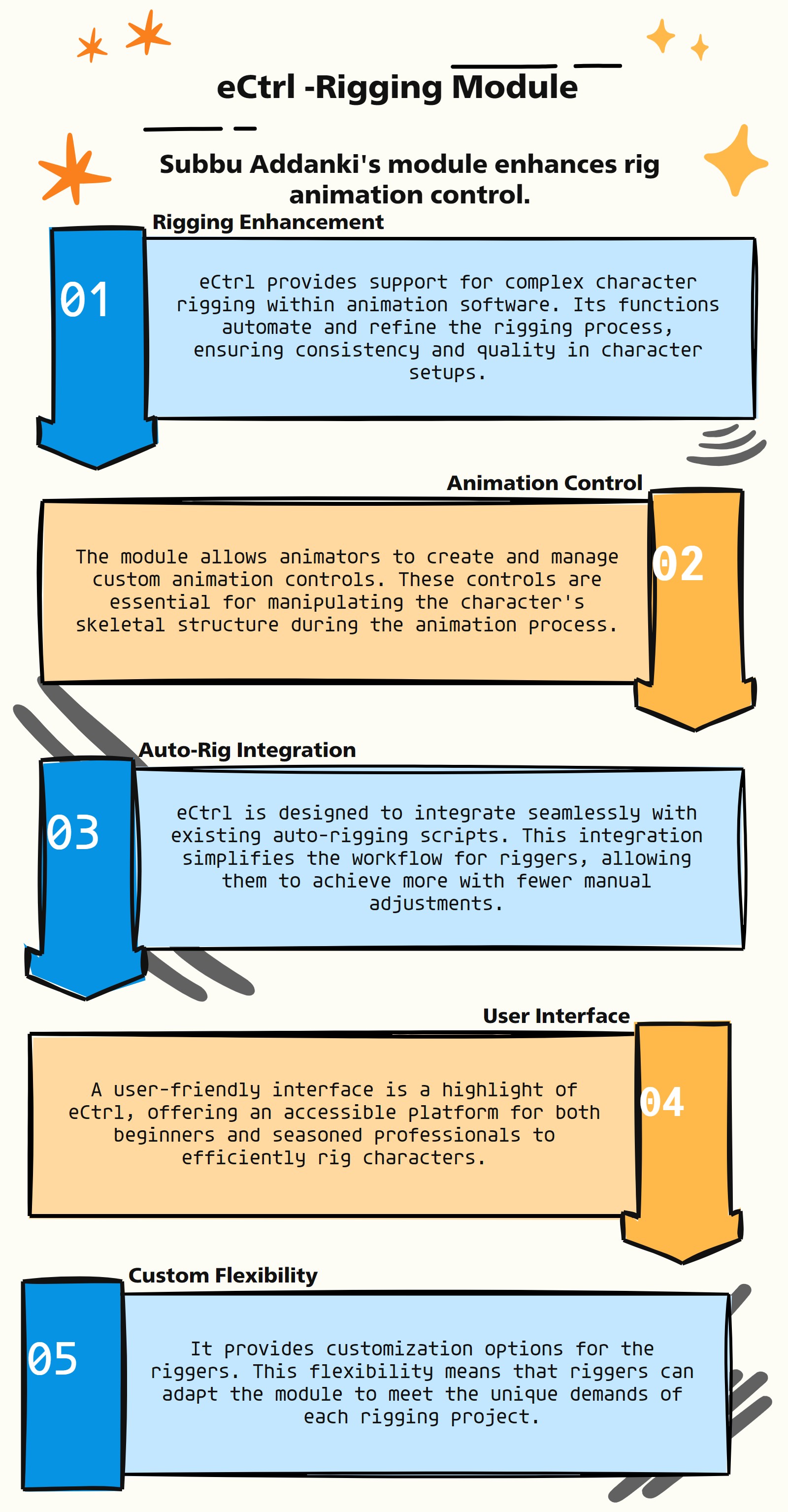
The eCtrl module, like the asNode module, is a custom Python module tailored for use in VFX, specifically in rigging and animation within Autodesk Maya. Here are a few potential uses or features of the eCtrl module:
Animation Control Rigging: eCtrl is designed to assist in building control rigs for animation. These rigs are crucial for animators to effectively manipulate 3D models.
Custom Control Creations: The module provides tools or functions for creating custom controls in a rig, allowing for more tailored and efficient animation setups.
User-Friendly Interface: eCtrl offers a user-friendly interface to interact with complex rigging and control systems in Maya, making it accessible to users with varying levels of scripting knowledge.
Efficiency in Rigging Process: By automating aspects of control rigging, the module significantly improve workflow efficiency, saving time and effort in the rigging process.
Integration with Maya’s API: It is designed to work seamlessly with Maya’s API, providing a more intuitive and Pythonic approach to rigging and animation tasks.
Enhanced Animation Workflow: eCtrl streamline the animation workflow by simplifying the process of setting up and manipulating control rigs.
Support for Complex Rigs: The module include features that support the creation and management of complex rigs, which are often required in detailed character animations.
- eCtrl.__init__(self)#
To Support main auto rig scripts via eCtrl
as_eCtrlMain_v1.5
About
Author: (Subbaiah) Subbu Addanki
Character Supervisor (Rigging) & Programmer
Visit
http://www.pythonscripting.com
http://subbuadd.blogspot.com
Contact
Mail Id: subbu.add@gmail.com
Mobile No: +91-9741454400 / +91-9949005359
Copyright (c) as_eCtrlMain
** (Subbaiah) Subbu Addanki. All Rights Reserved. **
- eCtrl.addAngleAttr(self, nodeList, name, value=0, k=1, h=0, **shArgs)#
[shArgs : nl=nodeList, na=name, v=value, k=keyable, h=hidden]
Purpose:
:: Adds an angle attribute to a specified node in Autodesk Maya.
Enhances nodes with angle attributes, useful in rigging and animation processes.
- Parameters:
nodeList – <str/list> # The name or list of names of nodes to which the angle attribute will be added.
name – <str> # The name of the angle attribute to be added.
value – <float, optional> # The default value of the angle attribute, set to 0 by default.
keyable – <int, optional> # Whether the attribute is keyable, set to 1 (True) by default.
hidden – <int, optional> # Whether the attribute is hidden, set to 0 (False) by default.
- Returns:
<pm.Attribute> # The newly added angle attribute on the node.
Code Examples:
>>> node_list = ["pCube1"]
>>> attr_name = "rotationAngle"
>>> default_value = 45.0
>>> keyable = 1
>>> hidden = 0
>>> added_attr = addAngleAttr(node_list, attr_name, default_value, keyable, hidden)
# Adds an angle attribute named 'rotationAngle' with a default value of 45.0 to 'pCube1', making it keyable and visible.
graph TB Start[("fa:fa-play Start")] --> CheckShArgs{"/fas:fa-question-circle Check shArgs"} CheckShArgs --"If shArgs Exist"--> ParseShArgs["/fas:fa-cogs Parse shArgs"] CheckShArgs --"If shArgs Does Not Exist"--> InitializeParameters["/fas:fa-wrench Initialize Parameters"] InitializeParameters --> GetNodeList{"/fas:fa-check-square Get Node List"} GetNodeList --"If Node List Exists"--> IterateNodes["/fas:fa-clipboard Iterate Nodes"] GetNodeList --"If Node List Does Not Exist"--> SelectNodes["/fas:fa-mouse-pointer Select Nodes"] IterateNodes --> AddAngleAttribute{"/fas:fa-plus-circle Add Angle Attribute"} AddAngleAttribute --> End["/fas:fa-stop End"] style Start fill:#00cc00,stroke:#000,stroke-width:3px style CheckShArgs fill:#ffcc00,stroke:#000,stroke-width:2px style ParseShArgs fill:#ff9999,stroke:#000,stroke-width:2px style InitializeParameters fill:#99ccff,stroke:#000,stroke-width:2px style GetNodeList fill:#cc99ff,stroke:#000,stroke-width:2px style IterateNodes fill:#99ff99,stroke:#000,stroke-width:2px style End fill:#ff6666,stroke:#000,stroke-width:3px- Flow Chart Description:
This flowchart illustrates the addAngleAttr function:
Checks if shArgs exist, and if so, parses the nodeList, name, value, k, and h from it.
If shArgs do not exist, initializes parameters with default values.
Retrieves a list of nodes to which the angle attribute will be added.
Iterates through the node list.
Adds an angle attribute with the specified name, value, k, and h to each node.
Ends the process.
- eCtrl.addBoolAttr(self, nodeList, name, value=True, **shArgs)#
[**shArgs : nl=nodeList, n=name, v=value]
Purpose:
:: Adds a boolean attribute to a node in Autodesk Maya.
This function is designed to create custom boolean attributes on nodes, allowing for enhanced node interactivity and control.
Useful in rigging, custom tools creation, and scene setup where boolean flags are required.
- Parameters:
nodeList – <str/list> # The name or list of names of nodes to which the attribute will be added.
name – <str> # The name of the boolean attribute to be added.
value – <bool, optional> # The default value of the boolean attribute. Defaults to True.
- Returns:
None # The function does not return a value but adds the attribute to the specified node(s).
Code Examples:
>>> nodes = ["node1", "node2"]
>>> attributeName = "isVisible"
>>> defaultValue = True
>>> addBoolAttr(nodes, attributeName, defaultValue)
# Adds a boolean attribute named 'isVisible' with a default value of True to 'node1' and 'node2'.
graph TB Start[("fa:fa-play Start")] --> CheckShArgs{"/fas:fa-question-circle Check shArgs"} CheckShArgs --"If shArgs Exist"--> ParseShArgs["/fas:fa-cogs Parse shArgs"] CheckShArgs --"If shArgs Does Not Exist"--> InitializeParameters["/fas:fa-wrench Initialize Parameters"] InitializeParameters --> GetNodeList{"/fas:fa-check-square Get Node List"} GetNodeList --"If Node List Exists"--> IterateNodes["/fas:fa-clipboard Iterate Nodes"] GetNodeList --"If Node List Does Not Exist"--> SelectNodes["/fas:fa-mouse-pointer Select Nodes"] IterateNodes --> AddBoolAttribute{"/fas:fa-plus-circle Add Boolean Attribute"} AddBoolAttribute --> SetDefaultValue{"/fas:fa-pencil-alt Set Default Value"} SetDefaultValue --> End["/fas:fa-stop End"] style Start fill:#00cc00,stroke:#000,stroke-width:3px style CheckShArgs fill:#ffcc00,stroke:#000,stroke-width:2px style ParseShArgs fill:#ff9999,stroke:#000,stroke-width:2px style InitializeParameters fill:#99ccff,stroke:#000,stroke-width:2px style GetNodeList fill:#cc99ff,stroke:#000,stroke-width:2px style IterateNodes fill:#99ff99,stroke:#000,stroke-width:2px style GetDefaultValue fill:#ffcc99,stroke:#000,stroke-width:2px style SetDefaultValue fill:#ccffcc,stroke:#000,stroke-width:2px style End fill:#ff6666,stroke:#000,stroke-width:3px- Flow Chart Description:
This flowchart illustrates the addBoolAttr function:
Checks if shArgs exist, and if so, parses the nodeList, name, and value from it.
If shArgs do not exist, initializes parameters with default values.
Retrieves a list of nodes to which the attribute will be added.
Iterates through the node list.
Adds a boolean attribute with the specified name to each node.
Sets the default value of the added boolean attribute.
Ends the process.
- eCtrl.addEnumAttr(nodeList, name, enumNames, k=1, h=0, **shArgs)#
[shArgs : n=nodeList, na=name, en=enumNames, k=keyable, h=hidden]
Purpose:
:: Adds an enumeration attribute to a node in Autodesk Maya.
Ideal for creating custom dropdown menus or selection options on Maya nodes.
- Parameters:
nodeList – <str> # The node to which the enumeration attribute will be added.
name – <str> # The name of the enumeration attribute to be added.
enumNames – <list> # A list of strings representing the names for the enumeration options.
keyable – <int, optional> # Whether the attribute is keyable, set to 1 (True) by default.
hidden – <int, optional> # Whether the attribute is hidden, set to 0 (False) by default.
- Returns:
<pm.Attribute> # The newly added enumeration attribute on the node.
Code Examples:
>>> node = "pCube1"
>>> attr_name = "colorOptions"
>>> enum_options = ["Red", "Green", "Blue"]
>>> keyable = 1
>>> hidden = 0
>>> addEnumAttr(node, attr_name, enum_options, keyable, hidden)
# Adds an enumeration attribute named 'colorOptions' to 'pCube1' with options 'Red', 'Green', 'Blue'.
graph TB Start[("fa:fa-play Start")] --> CheckShArgs{"/fas:fa-question-circle Check shArgs"} CheckShArgs --"If shArgs Exist"--> ParseShArgs["/fas:fa-cogs Parse shArgs"] CheckShArgs --"If shArgs Does Not Exist"--> InitializeParameters["/fas:fa-wrench Initialize Parameters"] InitializeParameters --> GetNodeList{"/fas:fa-check-square Get Node List"} GetNodeList --"If Node List Exists"--> AddEnumAttribute["/fas:fa-plus-circle Add Enum Attribute"] GetNodeList --"If Node List Does Not Exist"--> SelectNode["/fas:fa-mouse-pointer Select Node"] AddEnumAttribute --> End["/fas:fa-stop End"] style Start fill:#00cc00,stroke:#000,stroke-width:3px style CheckShArgs fill:#ffcc00,stroke:#000,stroke-width:2px style ParseShArgs fill:#ff9999,stroke:#000,stroke-width:2px style InitializeParameters fill:#99ccff,stroke:#000,stroke-width:2px style GetNodeList fill:#cc99ff,stroke:#000,stroke-width:2px style AddEnumAttribute fill:#99ff99,stroke:#000,stroke-width:2px style End fill:#ff6666,stroke:#000,stroke-width:3px- Flow Chart Description:
This flowchart illustrates the addEnumAttr function:
Checks if shArgs exist, and if so, parses the nodeList, name, enumNames, k, and h from it.
If shArgs do not exist, initializes parameters with default values.
Retrieves the node to which the enumeration attribute will be added.
Adds an enumeration attribute with the specified name, enumNames, k, and h to the node.
Ends the process.
- eCtrl.addFloatAttr(self, nodeList, name, value=0, k=1, h=0, minValue=None, maxValue=None, **shArgs)#
[shArgs : nl=nodeList, na=name, v=value, k=keyable, h=hidden, min=minValue, max=maxValue]
Purpose:
:: Adds a floating-point attribute to a node in Autodesk Maya.
Useful for adding custom float attributes to nodes, enabling finer control over various attributes and parameters.
- Parameters:
nodeList – <str/list> # The name or list of names of nodes to which the float attribute will be added.
name – <str> # The name of the float attribute to be added.
value – <float, optional> # The default value of the float attribute, set to 0 by default.
keyable – <int, optional> # Whether the attribute is keyable, set to 1 (True) by default.
hidden – <int, optional> # Whether the attribute is hidden, set to 0 (False) by default.
minValue – <float, optional> # The minimum value for the attribute.
maxValue – <float, optional> # The maximum value for the attribute.
- Returns:
<pm.Attribute> # The newly added float attribute on the node.
Code Examples:
>>> node_list = ["pCube1"]
>>> attr_name = "customFloat"
>>> default_value = 3.5
>>> keyable = 1
>>> hidden = 0
>>> min_value = 0.0
>>> max_value = 10.0
>>> added_attr = addFloatAttr(node_list, attr_name, default_value, keyable, hidden, min_value, max_value)
# Adds a float attribute named 'customFloat' to 'pCube1' with specified parameters.
graph TB Start[("fa:fa-play Start")] --> CheckShArgs{"/fas:fa-question-circle Check shArgs"} CheckShArgs --"If shArgs Exist"--> ParseShArgs["/fas:fa-cogs Parse shArgs"] CheckShArgs --"If shArgs Does Not Exist"--> InitializeParameters["/fas:fa-wrench Initialize Parameters"] InitializeParameters --> GetNodeList{"/fas:fa-check-square Get Node List"} GetNodeList --"If Node List Exists"--> IterateNodes["/fas:fa-clipboard Iterate Nodes"] GetNodeList --"If Node List Does Not Exist"--> SelectNodes["/fas:fa-mouse-pointer Select Nodes"] IterateNodes --> AddFloatAttribute{"/fas:fa-plus-circle Add Float Attribute"} AddFloatAttribute --> End["/fas:fa-stop End"] style Start fill:#00cc00,stroke:#000,stroke-width:3px style CheckShArgs fill:#ffcc00,stroke:#000,stroke-width:2px style ParseShArgs fill:#ff9999,stroke:#000,stroke-width:2px style InitializeParameters fill:#99ccff,stroke:#000,stroke-width:2px style GetNodeList fill:#cc99ff,stroke:#000,stroke-width:2px style IterateNodes fill:#99ff99,stroke:#000,stroke-width:2px style End fill:#ff6666,stroke:#000,stroke-width:3px- Flow Chart Description:
This flowchart illustrates the addFloatAttr function:
Checks if shArgs exist, and if so, parses the nodeList, name, value, k, h, minValue, and maxValue from it.
If shArgs do not exist, initializes parameters with default values.
Retrieves a list of nodes to which the float attribute will be added.
Iterates through the node list.
Adds a float attribute with the specified name, value, k, h, minValue, and maxValue to each node.
Ends the process.
- eCtrl.addIntAttr(self, nodeList, name, value=0, **shArgs)#
[**shArgs : nl=nodeList, na=name, v=value]
:: Adds an integer attribute to one or more nodes in Autodesk Maya.
- Parameters:
nodeList – (<type str/list>) # The name or list of names of nodes to which the attribute will be added.
name – (<type str>) # The name of the integer attribute to be added.
value – (<type int>, optional) # The default value of the integer attribute. Defaults to 0.
- Returns:
(<type pm.Attribute>) # The added integer attribute.
graph TB Start[("fa:fa-play Start")] --> CheckShArgs{"/fas:fa-question-circle Check shArgs"} CheckShArgs --"If shArgs Exist"--> ParseShArgs["/fas:fa-cogs Parse shArgs"] CheckShArgs --"If shArgs Does Not Exist"--> InitializeParameters["/fas:fa-wrench Initialize Parameters"] InitializeParameters --> GetNodeList{"/fas:fa-check-square Get Node List"} GetNodeList --"If Node List Exists"--> IterateNodes["/fas:fa-clipboard Iterate Nodes"] GetNodeList --"If Node List Does Not Exist"--> SelectNodes["/fas:fa-mouse-pointer Select Nodes"] IterateNodes --> AddIntAttribute{"/fas:fa-plus-circle Add Integer Attribute"} AddIntAttribute --> SetDefaultValue{"/fas:fa-pencil-alt Set Default Value"} SetDefaultValue --> End["/fas:fa-stop End"] style Start fill:#00cc00,stroke:#000,stroke-width:3px style CheckShArgs fill:#ffcc00,stroke:#000,stroke-width:2px style ParseShArgs fill:#ff9999,stroke:#000,stroke-width:2px style InitializeParameters fill:#99ccff,stroke:#000,stroke-width:2px style GetNodeList fill:#cc99ff,stroke:#000,stroke-width:2px style IterateNodes fill:#99ff99,stroke:#000,stroke-width:2px style GetDefaultValue fill:#ffcc99,stroke:#000,stroke-width:2px style SetDefaultValue fill:#ccffcc,stroke:#000,stroke-width:2px style End fill:#ff6666,stroke:#000,stroke-width:3px- Flow Chart Description:
This flowchart illustrates the addIntAttr function:
Checks if shArgs exist, and if so, parses the nodeList, name, and value from it.
If shArgs do not exist, initializes parameters with default values.
Retrieves a list of nodes to which the attribute will be added.
Iterates through the node list.
Adds an integer attribute with the specified name to each node.
Sets the default value of the added integer attribute.
Ends the process.
- eCtrl.addMatrixAttr(self, nodeList, name, **shArgs)#
[shArgs : nl=nodeList, na=name]
Purpose:
:: Adds a matrix attribute to a specified node in Autodesk Maya.
Facilitates the addition of complex matrix attributes to nodes for advanced operations and transformations.
- Parameters:
nodeList – <str/list> # The name or list of names of nodes to which the matrix attribute will be added.
name – <str> # The name of the matrix attribute to be added.
- Returns:
<pm.Attribute> # The newly added matrix attribute on the node.
Code Examples:
>>> node_list = ["pCube1", "pSphere1"]
>>> attr_name = "transformationMatrix"
>>> added_attr = addMatrixAttr(node_list, attr_name)
# This will add a matrix attribute named 'transformationMatrix' to 'pCube1' and 'pSphere1'.
graph TB Start[("fa:fa-play Start")] --> CheckShArgs{"/fas:fa-question-circle Check shArgs"} CheckShArgs --"If shArgs Exist"--> ParseShArgs["/fas:fa-cogs Parse shArgs"] CheckShArgs --"If shArgs Does Not Exist"--> InitializeParameters["/fas:fa-wrench Initialize Parameters"] InitializeParameters --> GetNodeList{"/fas:fa-check-square Get Node List"} GetNodeList --"If Node List Exists"--> IterateNodes["/fas:fa-clipboard Iterate Nodes"] GetNodeList --"If Node List Does Not Exist"--> SelectNodes["/fas:fa-mouse-pointer Select Nodes"] IterateNodes --> AddMatrixAttribute{"/fas:fa-plus-circle Add Matrix Attribute"} AddMatrixAttribute --> End["/fas:fa-stop End"] style Start fill:#00cc00,stroke:#000,stroke-width:3px style CheckShArgs fill:#ffcc00,stroke:#000,stroke-width:2px style ParseShArgs fill:#ff9999,stroke:#000,stroke-width:2px style InitializeParameters fill:#99ccff,stroke:#000,stroke-width:2px style GetNodeList fill:#cc99ff,stroke:#000,stroke-width:2px style IterateNodes fill:#99ff99,stroke:#000,stroke-width:2px style End fill:#ff6666,stroke:#000,stroke-width:3px- Flow Chart Description:
This flowchart illustrates the addMatrixAttr function:
Checks if shArgs exist, and if so, parses the nodeList and name from it.
If shArgs do not exist, initializes parameters with default values.
Retrieves a list of nodes to which the matrix attribute will be added.
Iterates through the node list.
Adds a matrix attribute with the specified name to each node.
Ends the process.
- eCtrl.addStringAttr(self, nodeList, name, value='', **shArgs)#
[**shArgs : nl=nodeList, n=name, v=value]
Purpose:
:: Adds a string attribute with a specified name and optional initial value to one or more nodes in Autodesk Maya.
- Parameters:
nodeList – (<type list>) # List of nodes to which the attribute will be added.
name – (<type str>) # Name of the string attribute to be added.
value – (<type str>, optional) # Initial value for the string attribute. Defaults to an empty string.
- Returns:
(<type pm.Attribute>) # The added string attribute.
graph TB Start[("fa:fa-play Start")] --> CheckShArgs{"/fas:fa-question-circle Check shArgs"} CheckShArgs --"If shArgs Exist"--> ParseShArgs["/fas:fa-cogs Parse shArgs"] CheckShArgs --"If shArgs Does Not Exist"--> InitializeParameters["/fas:fa-wrench Initialize Parameters"] InitializeParameters --> GetNodeList{"/fas:fa-check-square Get Node List"} GetNodeList --"If Node List Exists"--> IterateNodes["/fas:fa-clipboard Iterate Nodes"] GetNodeList --"If Node List Does Not Exist"--> SelectNodes["/fas:fa-mouse-pointer Select Nodes"] IterateNodes --> AddStringAttribute{"/fas:fa-plus-circle Add String Attribute"} AddStringAttribute --> SetInitialValue{"/fas:fa-pencil-alt Set Initial Value"} SetInitialValue --> End["/fas:fa-stop End"] style Start fill:#00cc00,stroke:#000,stroke-width:3px style CheckShArgs fill:#ffcc00,stroke:#000,stroke-width:2px style ParseShArgs fill:#ff9999,stroke:#000,stroke-width:2px style InitializeParameters fill:#99ccff,stroke:#000,stroke-width:2px style GetNodeList fill:#cc99ff,stroke:#000,stroke-width:2px style IterateNodes fill:#99ff99,stroke:#000,stroke-width:2px style GetInitialValue fill:#ffcc99,stroke:#000,stroke-width:2px style SetInitialValue fill:#ccffcc,stroke:#000,stroke-width:2px style End fill:#ff6666,stroke:#000,stroke-width:3px- Flow Chart Description:
This flowchart illustrates the addStringAttr function:
Checks if shArgs exist, and if so, parses the nodeList, name, and value from it.
If shArgs do not exist, initializes parameters with default values.
Retrieves a list of nodes to which the attribute will be added.
Iterates through the node list.
Adds a string attribute with the specified name to each node.
Sets the initial value of the added string attribute.
Ends the process.
- eCtrl.add_Attrs(self, ctrlList=None, attr='RotateOrder', attrDivider=True, **shArgs)#
[**shArgs : ctrlList =cl, attr =a, attrDivider =ad]
Purpose:
:: Adds specified attributes to a list of controllers in Autodesk Maya.
- Parameters:
ctrlList – (<type list, optional>) # The list of controllers to add the attribute to. Defaults to None.
attr – (<type str>) # The name of the attribute to add.
attrDivider – (<type bool, optional>) # Flag to add a divider for the attribute. Defaults to True.
- Returns:
(<type None>) # None
graph TB Start[("fa:fa-play Start")] --> CheckShArgs{"/fas:fa-question-circle Check shArgs"} CheckShArgs --"If shArgs Exist"--> ParseShArgs["/fas:fa-cogs Parse shArgs"] CheckShArgs --"If shArgs Does Not Exist"--> InitializeParameters["/fas:fa-wrench Initialize Parameters"] InitializeParameters --> GetSelectedObjects{"/fas:fa-check-square Get Selected Objects"} GetSelectedObjects --"For Each Selected Object"--> CheckCtrlList{"/fas:fa-question-circle Check Control List"} CheckCtrlList --"If Control List Exists"--> IterateCtrlList["/fas:fa-clipboard Iterate Control List"] CheckCtrlList --"If Control List Does Not Exist"--> SelectControls["/fas:fa-mouse-pointer Select Controls"] IterateCtrlList --> CheckControlType{"/fas:fa-question-circle Check Control Type"} CheckControlType --"If Control is Not a Curve"--> ContinueIteration["/fas:fa-arrow-right Continue Iteration"] CheckControlType --"If Control is a Curve"--> MirrorControl["/fas:fa-clone Mirror Control"] ContinueIteration --> IterateCtrlList MirrorControl --"If Letters are Considered"--> SnapVertices["/fas:fa-magnet Snap Vertices"] MirrorControl --"If Letters are Not Considered"--> MirrorVertices["/fas:fa-arrows Mirror Vertices"] SnapVertices --> CenterPivot["/fas:fa-crosshairs Center Pivot"] CenterPivot --> SnapShapeToOpposite["/fas:fa-hand-rock Snap Shape to Opposite"] SnapShapeToOpposite --> AppendToMirrList["/fas:fa-plus Append to Mirrored List"] MirrorVertices --> SelectVertices["/fas:fa-mouse-pointer Select Vertices"] SelectVertices --> CalculateOppositePosition["/fas:fa-calculator Calculate Opposite Position"] CalculateOppositePosition --> SetOppositePosition["/fas:fa-crosshairs Set Opposite Position"] SetOppositePosition --> AppendToMirrList AppendToMirrList --"For Each Control"--> IterateCtrlList IterateCtrlList --"If Control List is Not Empty"--> SelectMirroredControls["/fas:fa-mouse-pointer Select Mirrored Controls"] IterateCtrlList --"If Control List is Empty"--> End["/fas:fa-stop End"] style Start fill:#00cc00,stroke:#000,stroke-width:3px style CheckShArgs fill:#ffcc00,stroke:#000,stroke-width:2px style ParseShArgs fill:#ff9999,stroke:#000,stroke-width:2px style InitializeParameters fill:#99ccff,stroke:#000,stroke-width:2px style GetSelectedObjects fill:#cc99ff,stroke:#000,stroke-width:2px style CheckCtrlList fill:#99ff99,stroke:#000,stroke-width:2px style IterateCtrlList fill:#ffcc99,stroke:#000,stroke-width:2px style CheckControlType fill:#ccffcc,stroke:#000,stroke-width:2px style ContinueIteration fill:#99ccff,stroke:#000,stroke-width:2px style MirrorControl fill:#cc99ff,stroke:#000,stroke-width:2px style SnapVertices fill:#ffcc99,stroke:#000,stroke-width:2px style CenterPivot fill:#ccffcc,stroke:#000,stroke-width:2px style SnapShapeToOpposite fill:#99ff99,stroke:#000,stroke-width:2px style AppendToMirrList fill:#ffcc99,stroke:#000,stroke-width:2px style SelectVertices fill:#ccffcc,stroke:#000,stroke-width:2px style CalculateOppositePosition fill:#99ccff,stroke:#000,stroke-width:2px style SetOppositePosition fill:#cc99ff,stroke:#000,stroke-width:2px style SelectMirroredControls fill:#ffcc99,stroke:#000,stroke-width:2px style End fill:#ff6666,stroke:#000,stroke-width:3px- Flow Chart Description:
This flowchart illustrates the mirrorCtrlShapes function:
Checks if shArgs exist, and if so, parses the ctrlList, srcStr, repStr, repCount, and letters from it.
If shArgs do not exist, initializes parameters with default values.
Retrieves a list of selected controls (control curves).
- For each selected control:
Checks if it’s a curve shape (control shape).
If it’s not a curve shape, continues to the next control.
If it’s a curve shape, proceeds to mirror it.
- If letters are considered in the mirroring process:
Snaps vertices to their opposite positions.
Centers the pivot of the mirrored control.
Snaps the shape to the opposite location.
- If letters are not considered:
Mirrors vertices by changing their X-coordinates to the opposite side.
Appends the mirrored control to the list of mirrored controls.
After processing all controls, selects the mirrored controls if the list is not empty.
- eCtrl.applyCtrlColor(self, ctrlList=None, colorNum=None, LPrefix=None, RPrefix=None, CPrefix=None, **shArgs)#
[**shArgs : cl=ctrlList, cn=colorNum, lp=LPrefix, rp=RPrefix, cp=CPrefix]
Purpose:
:: Changes control colors based on prefix, colorVal
- Parameters:
ctrlList – (<type list>) # List of control names or a single control name.
colorNum – (<type int>) # The color value to set for the controls.
LPrefix – ([<type str>, <type int>]) # Left side prefix and its value for controls.
RPrefix – ([<type str>, <type int>]) # Right side prefix and its value for controls.
CPrefix – ([<type str>, <type int>]) # Custom prefix and its value for controls.
- Returns:
(<type None>) # None
Code Examples:
>>> control_list = ['LeftArm_Ctrl', 'RightArm_Ctrl']  # Specify a list of control names
>>> color_number = 17  # Specify the color value
>>> left_prefix = ['L', 6]  # Specify the prefix and color value for controls on the left side
>>> right_prefix = ['R', 13]  # Specify the prefix and color value for controls on the right side
>>> custom_prefix = ['C', 10]  # Specify the prefix and color value for custom controls
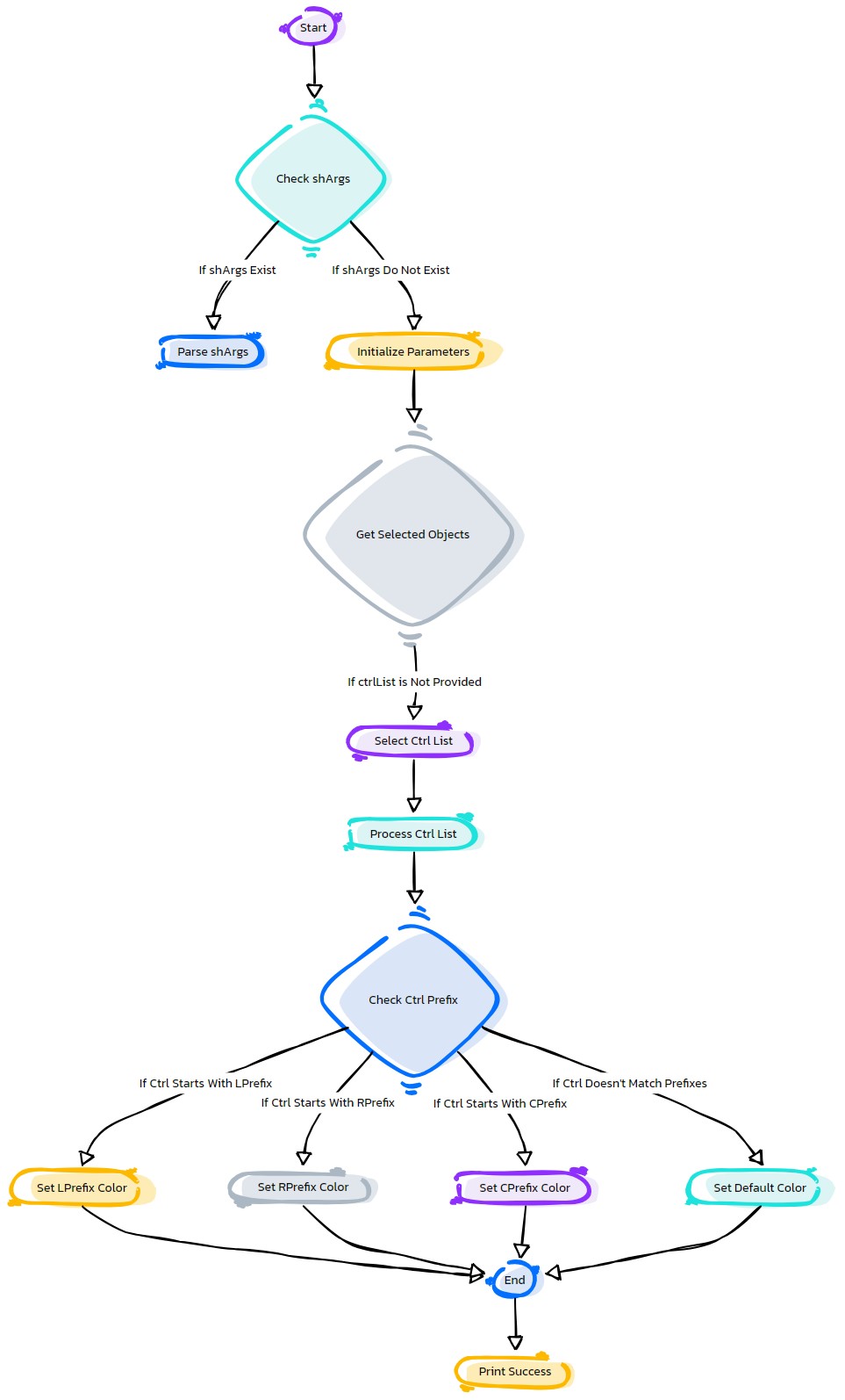
graph TB Start[("fa:fa-play Start")] --> CheckShArgs{"/fas:fa-question-circle Check shArgs"} CheckShArgs --"If shArgs Exist"--> ParseShArgs["/fas:fa-cogs Parse shArgs"] CheckShArgs --"If shArgs Does Not Exist"--> InitializeParameters["/fas:fa-wrench Initialize Parameters"] InitializeParameters --> GetSelectedObjects{"/fas:fa-check-square Get Selected Objects"} GetSelectedObjects --"If ctrlList is Not Provided"--> SelectCtrlList["/fas:fa-mouse-pointer Select Ctrl List"] SelectCtrlList --> ProcessCtrlList["/fas:fa-cog Process Ctrl List"] ProcessCtrlList --"For Each Ctrl in Ctrl List"--> CheckCtrlPrefix{"/fas:fa-question-circle Check Ctrl Prefix"} CheckCtrlPrefix --"If Ctrl Starts With LPrefix"--> SetLPrefixColor["/fas:fa-paint-brush Set LPrefix Color"] CheckCtrlPrefix --"If Ctrl Starts With RPrefix"--> SetRPrefixColor["/fas:fa-paint-brush Set RPrefix Color"] CheckCtrlPrefix --"If Ctrl Starts With CPrefix"--> SetCPrefixColor["/fas:fa-paint-brush Set CPrefix Color"] CheckCtrlPrefix --"If Ctrl Doesn't Match Prefixes"--> SetDefaultColor["/fas:fa-paint-brush Set Default Color"] SetLPrefixColor --> End["/fas:fa-stop End"] SetRPrefixColor --> End SetCPrefixColor --> End SetDefaultColor --> End End --> PrintSuccess["/fas:fa-check Success: Ctrl Color Applied"] style Start fill:#00cc00,stroke:#000,stroke-width:3px style CheckShArgs fill:#ffcc00,stroke:#000,stroke-width:2px style ParseShArgs fill:#ff9999,stroke:#000,stroke-width:2px style InitializeParameters fill:#99ccff,stroke:#000,stroke-width:2px style GetSelectedObjects fill:#cc99ff,stroke:#000,stroke-width:2px style SelectCtrlList fill:#ffcc99,stroke:#000,stroke-width:2px style ProcessCtrlList fill:#ccffcc,stroke:#000,stroke-width:2px style CheckCtrlPrefix fill:#99ff99,stroke:#000,stroke-width:2px style SetLPrefixColor fill:#ffcc99,stroke:#000,stroke-width:2px style SetRPrefixColor fill:#ccffcc,stroke:#000,stroke-width:2px style SetCPrefixColor fill:#99ccff,stroke:#000,stroke-width:2px style SetDefaultColor fill:#ff9999,stroke:#000,stroke-width:2px style PrintSuccess fill:#99ff99,stroke:#000,stroke-width:2px style End fill:#ff6666,stroke:#000,stroke-width:3px- Flow Chart Description:
This flowchart illustrates the applyCtrlColor function:
Checks if shArgs exist, and if so, parses the arguments.
If shArgs do not exist, initializes parameters with default values.
Retrieves a list of control names.
If ctrlList is not provided, selects the control list interactively.
- Processes each control in the control list:
Checks if the control name matches the specified prefixes (LPrefix, RPrefix, CPrefix).
Sets the color of the control based on the prefix or uses the default color.
Prints a success message after applying color to the controls.
- eCtrl.arrowCtrl(self, ctrlName=None, grpLevel=3, snapPiv=True, numArrows=4, initRot=[0, 0, 0], ctrlType=1, grpSufxList=None, colorVal=None, **shArgs)#
[**shArgs : ctrlName=n, grpLevel=gl, snapPiv=sp, numArrows=na, initRot=ir, ctrlType=ct, grpSufxList=gs, colorVal=cv]
Purpose:
:: Creates arrow-shaped control objects in Autodesk Maya with customizable properties such as number of arrows, initial rotation, and control type.
Ideal for rigging scenarios where arrow-shaped controls are required.
Offers a variety of control shapes and configurations for diverse rigging needs.
- Parameters:
ctrlName – <str, optional> #Name for the arrow control. Default naming used if not provided.
grpLevel – <int, optional> #Specifies the hierarchy level for grouping the control. Default is 3.
snapPiv – <bool, optional> #Determines whether to snap the pivot of the groups to the control. Default is True.
numArrows – <int, optional> #Specifies the number of arrows in the control. Default is 4.
initRot – <list, optional> #Initial rotation of the control, specified as [x, y, z]. Default is [0, 0, 0].
ctrlType – <int, optional> #Type of arrow control to create, with various shape options. Default is 1.
grpSufxList – <list, optional> #List of suffixes for the control’s groups. Default is None.
colorVal – <int, optional> #Color value to apply to the control. Default is None.
- Returns:
<list> #A list containing the arrow control and its top group as Maya nodes, based on grpLevel.
graph TB Start[("fa:fa-play Start")] --> CheckCtrlName{"/fas:fa-question-circle Check Control Name"} CheckCtrlName --"If ctrlName is specified"--> CreateCtrl[("/fas:fa-pencil-ruler Create Control")] CheckCtrlName --"If ctrlName is not specified"--> SetDefaultName[("/fas:fa-tag Set Default Name")] SetDefaultName --> CreateCtrl CreateCtrl --> ChooseCtrlType{{"/fas:fa-shapes Choose Control Type"}} ChooseCtrlType --"Type 1"--> Type1[("/fas:fa-arrow-right Create Arrow Type 1")] ChooseCtrlType --"Type 2"--> Type2[("/fas:fa-arrow-right Create Arrow Type 2")] ChooseCtrlType --"Type 3"--> Type3[("/fas:fa-arrow-right Create Arrow Type 3")] ChooseCtrlType --"Type 4"--> Type4[("/fas:fa-arrow-right Create Arrow Type 4")] ChooseCtrlType --"Type 5"--> Type5[("/fas:fa-arrow-right Create Arrow Type 5")] ChooseCtrlType --"Type 6"--> Type6[("/fas:fa-arrow-right Create Arrow Type 6")] Type1 --> FinalizeCtrl[("/fas:fa-check-square Finalize Control")] Type2 --> FinalizeCtrl Type3 --> FinalizeCtrl Type4 --> FinalizeCtrl Type5 --> FinalizeCtrl Type6 --> FinalizeCtrl FinalizeCtrl --> End[("fas:fa-stop-circle End")] style Start fill:#00cc00,stroke:#000,stroke-width:3px style CheckCtrlName fill:#ffcc00,stroke:#000,stroke-width:2px style SetDefaultName fill:#99ccff,stroke:#000,stroke-width:2px style CreateCtrl fill:#ff9999,stroke:#000,stroke-width:2px style ChooseCtrlType fill:#ffcc00,stroke:#000,stroke-width:2px style Type1 fill:#99ff99,stroke:#000,stroke-width:2px style Type2 fill:#cc99ff,stroke:#000,stroke-width:2px style Type3 fill:#99ccff,stroke:#000,stroke-width:2px style Type4 fill:#ffcc00,stroke:#000,stroke-width:2px style Type5 fill:#ff9999,stroke:#000,stroke-width:2px style Type6 fill:#99ff99,stroke:#000,stroke-width:2px style FinalizeCtrl fill:#cc99ff,stroke:#000,stroke-width:2px style End fill:#ff6666,stroke:#000,stroke-width:3px- Flow Chart Description:
This flowchart illustrates the arrowCtrl function:
The process starts by checking if a control name is provided.
If not specified, a default control name is set.
The control type is selected from six available options.
Based on the chosen type, an arrow-shaped control is created.
The control is then finalized with initial rotation, group level, pivot snapping, suffix list, and color value.
The function concludes with the return of the control and its top group.
- eCtrl.as_eCtrl(self)#
To Support writing main tools while there are repetitive tasks like creating controls with eCtrl module
- eCtrl.attrDivider(self, ctrlList=None, dividerName=None, **shArgs)#
[shArgs : cl=ctrlList, dn=dividerName]
Purpose:
:: Adds a divider attribute to a list of controls in Autodesk Maya, enhancing organization and readability.
Useful for segregating control attributes in complex rigs or scripts.
Adds divider ‘_’ * (4 to 12 range)
- Parameters:
ctrlList – <None/str/list, optional> # The list of control nodes to add the divider to. If None, operates on the selected nodes.
dividerName – <None/str, optional> # The name of the divider attribute. If None, uses a sequence of underscores.
- Returns:
None # This function does not return a value but modifies the control nodes directly.
Code Examples:
>>> control_list = ["ctrl1", "ctrl2"]
>>> divider_name = "SECTION"
>>> attrDivider(control_list, divider_name)
# Adds a divider named 'SECTION' to 'ctrl1' and 'ctrl2'.
graph TB Start[("fa:fa-play Start")] --> CheckShArgs{"/fas:fa-question-circle Check shArgs"} CheckShArgs --"If shArgs Exist"--> ParseShArgs["/fas:fa-cogs Parse shArgs"] CheckShArgs --"If shArgs Does Not Exist"--> InitializeParameters["/fas:fa-wrench Initialize Parameters"] InitializeParameters --> GetCtrlList{"/fas:fa-check-square Get Control List"} GetCtrlList --"If Control List Exists"--> AddDividerAttr["/fas:fa-plus-circle Add Divider Attribute"] GetCtrlList --"If Control List Does Not Exist"--> SelectControls["/fas:fa-mouse-pointer Select Controls"] AddDividerAttr --> End["/fas:fa-stop End"] style Start fill:#00cc00,stroke:#000,stroke-width:3px style CheckShArgs fill:#ffcc00,stroke:#000,stroke-width:2px style ParseShArgs fill:#ff9999,stroke:#000,stroke-width:2px style InitializeParameters fill:#99ccff,stroke:#000,stroke-width:2px style GetCtrlList fill:#cc99ff,stroke:#000,stroke-width:2px style AddDividerAttr fill:#99ff99,stroke:#000,stroke-width:2px style End fill:#ff6666,stroke:#000,stroke-width:3px- Flow Chart Description:
This flowchart illustrates the attrDivider function:
Checks if shArgs exist, and if so, parses the ctrlList and dividerName from it.
If shArgs do not exist, initializes parameters with default values.
Retrieves the list of control nodes to which the divider attribute will be added.
Adds a divider attribute with the specified dividerName or a sequence of underscores to the control nodes.
Ends the process.
- eCtrl.ballCtrl(self, ctrlName=None, grpLevel=3, initRot=[0, 0, 0], ctrlType=1, grpSufxList=None, **shArgs)#
[shArgs : ctrlName=n, grpLevel=gl, initRot=ir, ctrlType=ct, grpSufxList=gsl]
Purpose:
:: Generates a ball-shaped control in Autodesk Maya, providing a versatile tool for rigging and animation tasks.
Useful for creating controls that require a spherical shape, such as for eye rigs or pivot points in mechanical rigs.
The ability to define control types and group suffixes allows for greater adaptability in rig setups.
- Parameters:
ctrlName – <str, optional> # Name for the ball control. If not specified, a default name is used.
grpLevel – <int, optional> # Specifies the hierarchy level for grouping the control. Default is 3.
initRot – <list, optional> # Initial rotation of the control, specified as [x, y, z]. Default is [0, 0, 0].
ctrlType – <int, optional> # Determines the style of the ball control. Default is 1.
grpSufxList – <list, optional> # List of suffixes for group names, if needed. Default is None.
- Returns:
<list> # A list containing the ball control and its top group as Maya nodes, structured as per grpLevel.
Code Examples:
>>> ball_control = ballCtrl(ctrlName="myBallCtrl", grpLevel=2, ctrlType=1)
# Creates a ball control with specified name, group level, and control type.
:param ctrlName : name(str) #_ name for the control which is going to be created :param grpLevl : num(int) #_ Number of top groups on control to be created :param initRot : [float, float, float] #_ Rotates the shape initially :param ctrlType : 1|2 (Max: 2) #_ Shape1 : Single Circle, Shape2 : Dual Circle :param grpSufxList (list, optional): List of suffixes for group names. Defaults to None. :return: List of Nodes (control and top group) as asNodes.
Usage:
ctrl              =eCtrl.ballCtrl(ctrlName)[0]
ctrlGrp           =eCtrl.ballCtrl(ctrlName)[-1]
ctrl, ctrlGrp =eCtrl.ballCtrl(ctrlName)
Returns:
if grpLevel:
        return [ctrl, ctrlGrp(topGrp)]  #_ asNodes
else:
        return [ctrl, ctrl]                     #_ asNodes
graph TD Start[("fa:fa-play Start")] --> CheckShArgs{"/fas:fa-question-circle Check shArgs"} CheckShArgs --"If shArgs Exist"--> ParseShArgs["/fas:fa-cogs Parse shArgs"] CheckShArgs --"If shArgs Does Not Exist"--> InitializeParameters["/fas:fa-wrench Initialize Parameters"] InitializeParameters --> GenerateControl["/fas:fa-circle Generate Control"] GenerateControl --> RotateControl["/fas:fa-redo Rotate Control"] RotateControl --> GroupControl["/fas:fa-object-group Group Control"] GroupControl --> ApplyColor["/fas:fa-paint-brush Apply Color"] ApplyColor --> End["/fas:fa-stop End"] style Start fill:#00cc00,stroke:#000,stroke-width:3px style CheckShArgs fill:#ffcc00,stroke:#000,stroke-width:2px style ParseShArgs fill:#ff9999,stroke:#000,stroke-width:2px style InitializeParameters fill:#99ccff,stroke:#000,stroke-width:2px style GenerateControl fill:#99ff99,stroke:#000,stroke-width:2px style RotateControl fill:#99ff99,stroke:#000,stroke-width:2px style GroupControl fill:#99ff99,stroke:#000,stroke-width:2px style ApplyColor fill:#99ff99,stroke:#000,stroke-width:2px style End fill:#ff6666,stroke:#000,stroke-width:3px- Flow Chart Description:
This flowchart illustrates the ballCtrl function:
Checks if shArgs exist, and if so, parses the function arguments from it.
If shArgs do not exist, initializes parameters with default values.
Generates a ball-shaped control in Autodesk Maya based on the specified control type.
Rotates the control based on the initRot parameter.
Groups the control based on the grpLevel and grpSufxList parameters.
Applies color to the control using the applyCtrlColor method.
Ends the process.
- eCtrl.boxCtrl(self, ctrlName=None, grpLevel=1, snapPiv=False, grpSufxList=None, grpPrfxList=None, ctrlType=1, ctrl2Axis='x', **shArgs)#
[**shArgs : ctrlName =n, grpLevel =gl, snapPiv =sp, grpSufxList =gsl, grpPrfxList =gpl, ctrlType =ct, ctrl2Axis =c2a]
Purpose:
:: Creates a box-shaped control in Autodesk Maya, offering flexibility in design and application. The control can be customized in terms of size, group level, pivot snapping, and axis orientation.
This function is beneficial for rigging and animation where box-shaped controls are needed.
It allows for adjustments in grouping, pivot snapping, and control axis to suit various rigging requirements.
- Parameters:
ctrlName – <str, optional> #Name for the control to be created. If not provided, defaults to ‘as_Box_Ctrl’.
grpLevel – <int, optional> #Number of top groups for the control. Default is 1.
snapPiv – <bool, optional> #Determines if group’s pivot should snap to the control. Default is False.
grpSufxList – <list, optional> #List of suffixes for group names. Defaults to None.
grpPrfxList – <list, optional> #List of prefixes for group names. Defaults to None.
ctrlType – <int> #Defines the type of the control shape. Default is 1.
ctrl2Axis – <str> #Axis for the control orientation. Defaults to ‘x’.
- Returns:
<list> #List of Nodes (control and top group) as asNodes, depending on the specified grpLevel.
graph TB Start[("fa:fa-play Start")] --> CheckCtrlName{"/fas:fa-question-circle Check Control Name"} CheckCtrlName --"If ctrlName is specified"--> CreateCtrl[("/fas:fa-pencil-ruler Create Control")] CheckCtrlName --"If ctrlName is not specified"--> SetDefaultName[("/fas:fa-tag Set Default Name")] SetDefaultName --> CreateCtrl CreateCtrl --> ChooseCtrlType{{"/fas:fa-shapes Choose Control Type"}} ChooseCtrlType --"Type 1"--> Type1[("/fas:fa-cube Create Box Type 1")] ChooseCtrlType --"Type 2"--> Type2[("/fas:fa-cubes Create Box Type 2")] Type1 --> FinalizeCtrl[("/fas:fa-check-square Finalize Control")] Type2 --> CheckAxis{{"/fas:fa-arrows-alt Check Axis"}} CheckAxis --"Axis X"--> AxisX[("/fas:fa-arrows-alt-h Align to X-axis")] CheckAxis --"Axis Y"--> AxisY[("/fas:fa-arrows-alt-v Align to Y-axis")] AxisX --> FinalizeCtrl AxisY --> FinalizeCtrl FinalizeCtrl --> End[("fas:fa-stop-circle End")] style Start fill:#00cc00,stroke:#000,stroke-width:3px style CheckCtrlName fill:#ffcc00,stroke:#000,stroke-width:2px style SetDefaultName fill:#99ccff,stroke:#000,stroke-width:2px style CreateCtrl fill:#ff9999,stroke:#000,stroke-width:2px style ChooseCtrlType fill:#ffcc00,stroke:#000,stroke-width:2px style Type1 fill:#99ff99,stroke:#000,stroke-width:2px style Type2 fill:#cc99ff,stroke:#000,stroke-width:2px style CheckAxis fill:#99ccff,stroke:#000,stroke-width:2px style AxisX fill:#ffcc00,stroke:#000,stroke-width:2px style AxisY fill:#ff9999,stroke:#000,stroke-width:2px style FinalizeCtrl fill:#cc99ff,stroke:#000,stroke-width:2px style End fill:#ff6666,stroke:#000,stroke-width:3px- Flow Chart Description:
This flowchart illustrates the boxCtrl function:
The function starts by checking if a control name is specified.
If not, a default control name is assigned.
The control type is selected between two options.
For Type 1, a simple box control is created.
For Type 2, the function checks the specified axis for alignment.
The control is then aligned according to the chosen axis (X or Y).
The control is finalized with group levels, pivot snapping, suffixes, and prefixes.
The function ends by returning the control and its top group.
- eCtrl.bulletCtrl(self, ctrlName=None, grpLevel=1, initRot=[0, 0, 0], ctrlType=1, **shArgs)#
[**shArgs : ctrlName =n, grpLevel =gl, initRot =ir, ctrlType =ct]
Purpose:
:: Creates a bullet-shaped control in Autodesk Maya, ideal for specific rigging needs such as projectiles or fast-moving objects.
The bullet control is perfect for animations involving projectiles or for rigging characters with bullet-like features.
The control’s shape and size can be adjusted to match various design requirements, making it versatile for different scenarios.
- Parameters:
ctrlName – <str, optional> #Name for the control which is going to be created
grpLevel – <int, optional> #Number of top groups on control to be created
initRot – <list, optional> #Rotates the shape initially
ctrlType – <int, optional> #Shape options. Shape1: Single Circle, Shape2: Dual Circle
- Returns:
<list> #A list containing the control and its top group as Maya nodes, based on grpLevel.
graph TB Start[("fa:fa-play Start")] --> CheckCtrlName{"/fas:fa-question-circle Check Control Name"} CheckCtrlName --"If ctrlName is specified"--> CreateCtrl[("/fas:fa-pencil-ruler Create Control")] CheckCtrlName --"If ctrlName is not specified"--> SetDefaultName[("/fas:fa-tag Set Default Name")] SetDefaultName --> CreateCtrl CreateCtrl --> CheckCtrlType{"/fas:fa-question-circle Check Control Type"} CheckCtrlType --"Control Type 1"--> CreateCurve[("/fas:fa-pencil-ruler Create Bullet Curve")] CheckCtrlType --"Control Type 2"--> CreateCircle[("/fas:fa-circle Create Circle")] CreateCurve --> RotateAndFreeze[("/fas:fa-sync-alt Rotate and Freeze Transform")] CreateCircle --> RotateAndFreeze RotateAndFreeze --> FinalizeCtrl[("/fas:fa-check-circle Finalize Control")] FinalizeCtrl --> End[("fas:fa-stop-circle End")] style Start fill:#00cc00,stroke:#000,stroke-width:3px style CheckCtrlName fill:#ffcc00,stroke:#000,stroke-width:2px style SetDefaultName fill:#99ccff,stroke:#000,stroke-width:2px style CreateCtrl fill:#ff9999,stroke:#000,stroke-width:2px style CheckCtrlType fill:#ffcc00,stroke:#000,stroke-width:2px style CreateCurve fill:#99ff99,stroke:#000,stroke-width:2px style CreateCircle fill:#99ff99,stroke:#000,stroke-width:2px style RotateAndFreeze fill:#cc99ff,stroke:#000,stroke-width:2px style FinalizeCtrl fill:#99ff99,stroke:#000,stroke-width:2px style End fill:#ff6666,stroke:#000,stroke-width:3px- Flow Chart Description:
This flowchart illustrates the bulletCtrl function:
The process starts by checking if a control name is specified.
If not specified, a default control name is set.
Depending on the control type, either a bullet curve or a circle is created.
The control is rotated and its transformations are frozen.
The control is finalized by creating its group and applying color.
The process ends with the creation of the bullet control and its group.
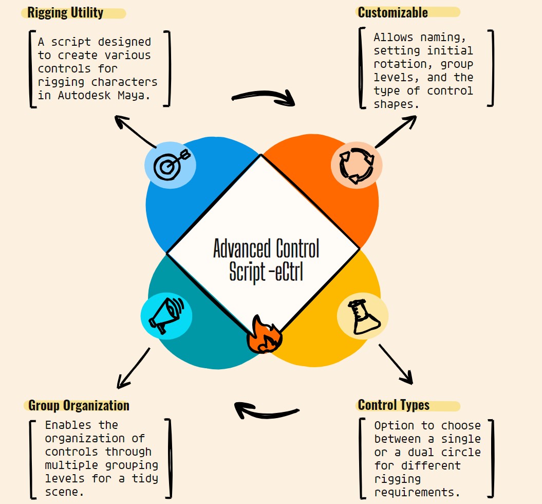
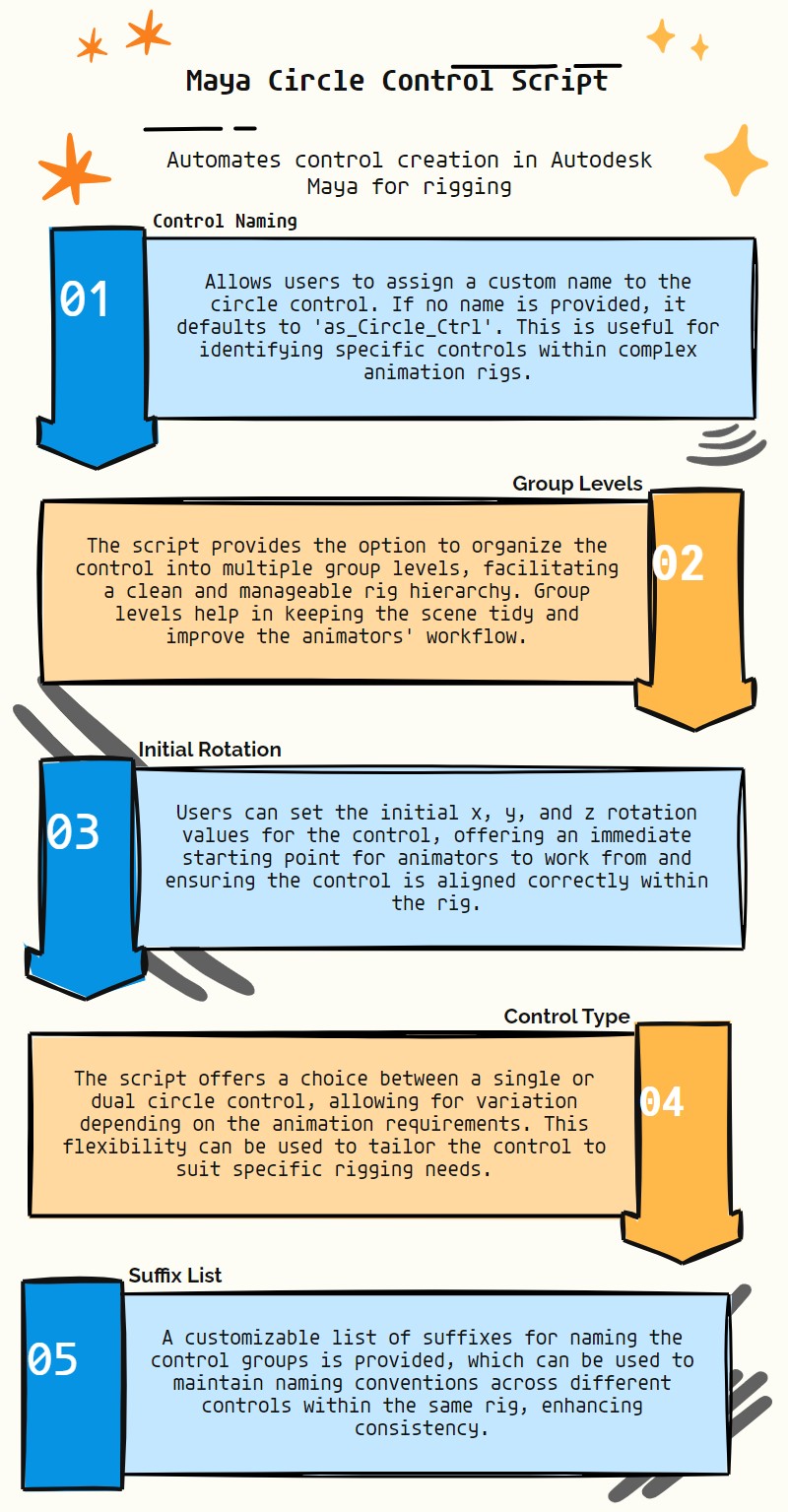
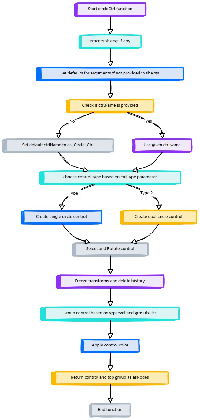
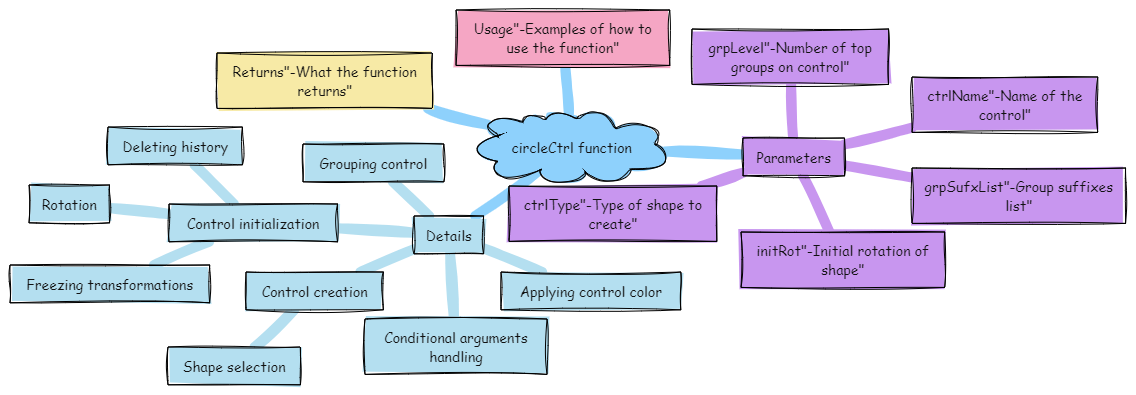
- eCtrl.circleCtrl(self, ctrlName=None, grpLevel=2, initRot=[0, 0, 0], ctrlType=1, grpSufxList=None, **shArgs)#
[shArgs : ctrlName=n, grpLevel=gl, initRot=ir, ctrlType=ct, grpSufxList=gsl]
Purpose:
:: Efficiently generates a circular control in Autodesk Maya, ideal for rigging and animation purposes.
The circle control serves as a versatile rigging element for various animation needs, providing intuitive manipulation for animators.
Customizable rotation, group levels, and multiple shape options enhance the utility and adaptability of the control in a rigging context.
- Parameters:
ctrlName – <str, optional> # Name to assign to the circle control. Defaults to ‘as_Circle_Ctrl’ if None.
grpLevel – <int, optional> # Number of grouping levels for organizing the control in the scene. Default is 2.
initRot – <list> # Initial rotation of the control, specified as [x, y, z].
ctrlType – <int, optional> # Type of circle control, with options 1 for a single circle and 2 for a dual circle. Default is 1.
grpSufxList – <list, optional> # List of suffixes for naming the control groups. Defaults to None.
- Returns:
<list> # A list containing the circle control and its top group as asNodes.
Code Examples:
>>> circle_control = circleCtrl(ctrlName="myCircleCtrl", grpLevel=3, initRot=[45, 0, 0], ctrlType=2)
# Creates a dual circle control named "myCircleCtrl" with specific rotation and group level.
- eCtrl.clavicleCtrl(self, ctrlName=None, sidePos='L_', grpLevel=1, ctrlType=1, initRot=[0, 0, 0], **shArgs)#
[shArgs : cn=ctrlName, sp=sidePos, gl=grpLevel, ct=ctrlType, ir=initRot]
Purpose:
:: Creates a clavicle control in Autodesk Maya, typically used in character rigging for shoulder movement.
The clavicle control assists in creating realistic shoulder and upper torso animations.
Offers customization in terms of side position, group level, control type, and initial rotation.
- Parameters:
ctrlName – <str, optional> # Name for the clavicle control. Default is generated if not provided.
sidePos – <str, optional> # Side position for the control, typically ‘L_’ for left or ‘R_’ for right. Default is ‘L_’.
grpLevel – <int, optional> # Hierarchy level for grouping the control. Default is 1.
ctrlType – <int, optional> # Type of the clavicle control to be created. Default is 1.
initRot – <list, optional> # Initial rotation of the control, given as [x, y, z]. Default is [0, 0, 0].
- Returns:
<list> # A list containing the control and its top group as Maya nodes, based on grpLevel.
Code Examples:
>>> control_name = "clavicleControl"
>>> side_position = "L_"
>>> group_level = 1
>>> control_type = 1
>>> initial_rotation = [0, 45, 0]
>>> clavicle_control = clavicleCtrl(control_name, side_position, group_level, control_type, initial_rotation)
# Creates a left-sided clavicle control with specified parameters.
graph TB Start[("fa:fa-play Start")] --> CheckSidePos{{"/fas:fa-check-circle Check Side Position"}} CheckSidePos --"Side Position 'L_' or 'LT_'"--> CreateCtrlL[("/fas:fa-plus-circle Create Ctrl 'L_'")] CheckSidePos --"Side Position 'R_' or 'RT_'"--> CreateCtrlR[("/fas:fa-plus-circle Create Ctrl 'R_'")] CreateCtrlL --> FinalizeCtrlL[("/fas:fa-cog Finalize Ctrl 'L_'")] CreateCtrlR --> FinalizeCtrlR[("/fas:fa-cog Finalize Ctrl 'R_'")] FinalizeCtrlL --> End[("fas:fa-stop-circle End")] FinalizeCtrlR --> End style Start fill:#00cc00,stroke:#000,stroke-width:3px style CheckSidePos fill:#ffcc00,stroke:#000,stroke-width:2px style CreateCtrlL fill:#99ff99,stroke:#000,stroke-width:2px style CreateCtrlR fill:#99ccff,stroke:#000,stroke-width:2px style FinalizeCtrlL fill:#cc99ff,stroke:#000,stroke-width:2px style FinalizeCtrlR fill:#ff9999,stroke:#000,stroke-width:2px style End fill:#ff6666,stroke:#000,stroke-width:3px- Flow Chart Description:
This flowchart illustrates the clavicleCtrl function:
Based on the side position, the corresponding clavicle control is created.
The control is then finalized by applying initial rotation, freezing transformations, and setting the group level.
The function concludes by returning the control and its top group as Maya nodes.
- eCtrl.cogCtrl(self, ctrlName=None, grpLevel=1, ctrlType=1, **shArgs)#
[shArgs : cn=ctrlName, gl=grpLevel, ct=ctrlType]
Purpose:
:: Creates a cog control in Autodesk Maya, suitable for Center of Gravity (COG) setups.
This control is ideal for rigging characters or objects where a COG control is required.
Offers flexibility in control design with options for different types and group levels.
- Parameters:
ctrlName – <str, optional> # Name for the cog control. Default is ‘as_COG_Ctrl’.
grpLevel – <int> # The number of top groups on the control to be created.
ctrlType – <int> # Type of COG control to create. Options include 1 for Single Circle, 2 for Dual Circle.
- Returns:
<list> # A list containing the control and its top group as Maya nodes, based on grpLevel.
Code Examples:
>>> control_name = "COG_Control"
>>> group_level = 2
>>> control_type = 1
>>> cogControl = cogCtrl(control_name, group_level, control_type)
# This creates a COG control with specified name, group level, and type.
graph TB Start[("fa:fa-play Start")] --> CheckShArgs{"/fas:fa-question-circle Check shArgs"} CheckShArgs --"If shArgs Exist"--> ParseShArgs["/fas:fa-cogs Parse shArgs"] CheckShArgs --"If shArgs Does Not Exist"--> InitializeParameters["/fas:fa-wrench Initialize Parameters"] InitializeParameters --> CreateCogControl{"/fas:fa-pen-nib Create COG Control"} ParseShArgs --"If shArgs Exist"--> CreateCogControl CreateCogControl --"Create COG Control"--> CreateControlGroup["/fas:fa-object-group Create Control Group"] CreateControlGroup --"Create Control Group"--> SnapPivotToControl["/fas:fa-crosshairs Snap Pivot to Control"] SnapPivotToControl --"Snap Pivot to Control"--> ApplyControlColor["/fas:fa-paint-brush Apply Control Color"] ApplyControlColor --"Apply Control Color"--> End["/fas:fa-stop End"] style Start fill:#00cc00,stroke:#000,stroke-width:3px style CheckShArgs fill:#ffcc00,stroke:#000,stroke-width:2px style ParseShArgs fill:#ff9999,stroke:#000,stroke-width:2px style InitializeParameters fill:#99ccff,stroke:#000,stroke-width:2px style CreateCogControl fill:#ccffcc,stroke:#000,stroke-width:2px style CreateControlGroup fill:#99ccff,stroke:#000,stroke-width:2px style SnapPivotToControl fill:#ffcc99,stroke:#000,stroke-width:2px style ApplyControlColor fill:#ff6666,stroke:#000,stroke-width:3px style End fill:#ff6666,stroke:#000,stroke-width:3px- Flow Chart Description:
This flowchart illustrates the cogCtrl function:
Checks if shArgs exist and parses them if present.
Initializes parameters for control creation, including ctrlName, grpLevel, and ctrlType.
Creates a COG control with the specified ctrlName and ctrlType.
Creates a control group based on the grpLevel.
Snaps the pivot of the control to the control itself.
Applies control color to the control.
- eCtrl.coneCtrl(self, ctrlName=None, grpLevel=3, ctrlType=2, initRot=[0, 0, 0], snapPiv=1, grpSufxList=None, colorVal=None, **shArgs)#
[**shArgs : ctrlName =n, grpLevel =gl, ctrlType =ct, initRot =ir, snapPiv =sp, grpSufxList =gsl, colorVal =cv]
Purpose:
:: Creates a cone-shaped control with customization options for initial rotation, type, group suffixes, pivot snapping, and color. :: Useful for rigging and animation control setups in Autodesk Maya.
- Parameters:
ctrlName – (<str>, optional) # Name for the control. Defaults to ‘as_Cone_Ctrl’ if not provided.
grpLevel – (<int>) # Number of top groups on the control to be created.
ctrlType – (<int>) # Defines the type of cone control to create.
initRot – (<list of floats>, optional) # Initial rotation of the control shape. Defaults to [0, 0, 0] if not provided.
snapPiv – (<int>) # Determines if the pivot is snapped (0 or 1).
grpSufxList – (<list>, optional) # List of suffixes for the control groups.
colorVal – (<any>, optional) # Color value for the control.
- Returns:
(<list>) # If grpLevel is provided, returns [ctrl, ctrlGrp(topGrp)] as asNodes; otherwise, returns [ctrl, ctrl].
Code Examples:
>>> ctrl_name = "myConeCtrl"
>>> group_level = 3
>>> control_type = 2
>>> initial_rotation = [45, 0, 0]
>>> snap_pivot = 1
>>> group_suffix_list = ["grp1", "grp2"]
>>> color_value = "red"
>>> ctrl, ctrl_grp = eCtrl.coneCtrl(ctrl_name, group_level, control_type, initial_rotation, snap_pivot, group_suffix_list, color_value)
# Creates a cone control with specified parameters.
graph TB Start[("fa:fa-play Start")] --> CheckShArgs{"/fas:fa-question-circle Check shArgs"} CheckShArgs --"If shArgs Exist"--> ParseShArgs["/fas:fa-cogs Parse shArgs"] CheckShArgs --"If shArgs Does Not Exist"--> InitializeParameters["/fas:fa-wrench Initialize Parameters"] InitializeParameters --> CreateConeControl{"/fas:fa-pen-nib Create Cone Control"} ParseShArgs --"If shArgs Exist"--> CreateConeControl CreateConeControl --"Create Cone Control"--> FinalizeControl["/fas:fa-check-circle Finalize Control"] FinalizeControl --"Finalize Control"--> End["/fas:fa-stop End"] style Start fill:#00cc00,stroke:#000,stroke-width:3px style CheckShArgs fill:#ffcc00,stroke:#000,stroke-width:2px style ParseShArgs fill:#ff9999,stroke:#000,stroke-width:2px style InitializeParameters fill:#99ccff,stroke:#000,stroke-width:2px style CreateConeControl fill:#ccffcc,stroke:#000,stroke-width:2px style FinalizeControl fill:#99ccff,stroke:#000,stroke-width:2px style End fill:#ff6666,stroke:#000,stroke-width:3px- Flow Chart Description:
This flowchart illustrates the coneCtrl function:
Checks if shArgs exist and parses them if present.
Initializes parameters for control creation, including ctrlName, grpLevel, ctrlType, initRot, snapPiv, grpSufxList, and colorVal.
Creates a cone control with the specified parameters.
Finalizes the control by calling the finalizeCtrl function.
Ends the process.
- eCtrl.createCtrlDir(self, trgtObj=None, ctrlName=None, **shArgs)#
[shArgs: to=trgtObj, cn=ctrlName]
Purpose:
:: Facilitates the creation of direction controls, essential for rigging joints like eyes, knees, or elbows.
Offers a streamlined approach to setting up directional constraints for rigging.
Enhances rigging precision, especially for pivotal joints requiring directional guidance.
- Parameters:
trgtObj – <str> #The target object, usually a joint, for the control direction (e.g., eyeJnt, kneeJnt).
ctrlName – <str, optional> #The name for the control to be created. If not specified, derived from the target object.
- Returns:
<Maya Node> #The created control direction node, typically an annotation object.
Code Examples:
>>> createCtrlDir(trgtObj="eyeJnt", ctrlName="eyeDirectionCtrl")
# Creates a direction control for the 'eyeJnt' named 'eyeDirectionCtrl'.

>>> createCtrlDir(trgtObj="kneeJnt")
# Creates a direction control for the 'kneeJnt' with an auto-generated name.
graph TB Start[("fa:fa-play Start")] --> CheckShArgs{{"/fas:fa-question Check shArgs"}} CheckShArgs --"shArgs provided"--> UpdateArgs[("/fas:fa-sync-alt Update Arguments")] CheckShArgs --"shArgs not provided"--> CheckSelection{{"/fas:fa-check-circle Check Selection"}} UpdateArgs --> DetermineTargets[("/fas:fa-crosshairs Determine Targets")] CheckSelection --"Two objects selected"--> AssignTargets[("/fas:fa-tasks Assign Targets")] CheckSelection --"Invalid or no selection"--> End[("fas:fa-stop-circle End")] AssignTargets --> DetermineTargets DetermineTargets --> CreateLocator[("/fas:fa-map-marker-alt Create Locator")] CreateLocator --> CreateAnnotation[("/fas:fa-pencil-alt Create Annotation")] CreateAnnotation --> PositionAnnObj[("/fas:fa-arrows-alt Position Annotation Object")] PositionAnnObj --> ParentAnnObj[("/fas:fa-sitemap Parent Annotation Object")] ParentAnnObj --> SnapLocator[("/fas:fa-location-arrow Snap Locator")] SnapLocator --> ParentLocator[("/fas:fa-sitemap Parent Locator")] ParentLocator --> ApplyConstraints[("/fas:fa-link Apply Constraints")] ApplyConstraints --> TemplateAnnotation[("/fas:fa-eye-slash Template Annotation")] TemplateAnnotation --> ReturnAnnObj[("fas:fa-check Return Annotation Object")] ReturnAnnObj --> End style Start fill:#00cc00,stroke:#000,stroke-width:3px style CheckShArgs fill:#ffcc00,stroke:#000,stroke-width:2px style UpdateArgs fill:#ff9999,stroke:#000,stroke-width:2px style CheckSelection fill:#99ccff,stroke:#000,stroke-width:2px style AssignTargets fill:#cc99ff,stroke:#000,stroke-width:2px style DetermineTargets fill:#ffcc66,stroke:#000,stroke-width:2px style CreateLocator fill:#99ff99,stroke:#000,stroke-width:2px style CreateAnnotation fill:#66ccff,stroke:#000,stroke-width:2px style PositionAnnObj fill:#f0ad4e,stroke:#000,stroke-width:2px style ParentAnnObj fill:#d9534f,stroke:#000,stroke-width:2px style SnapLocator fill:#5bc0de,stroke:#000,stroke-width:2px style ParentLocator fill:#f0ad4e,stroke:#000,stroke-width:2px style ApplyConstraints fill:#d9534f,stroke:#000,stroke-width:2px style TemplateAnnotation fill:#5bc0de,stroke:#000,stroke-width:2px style ReturnAnnObj fill:#5cb85c,stroke:#000,stroke-width:2px style End fill:#ff6666,stroke:#000,stroke-width:3px- Flow Chart Description:
This flowchart illustrates the createCtrlDir function:
The function starts by checking if shArgs are provided and updates arguments accordingly.
If no arguments are provided, it checks the current selection and assigns targets if two objects are selected.
Determines the target object and control name, then creates a locator for direction.
An annotation object is created and positioned according to the target.
The annotation object is parented to the target and the locator is snapped and parented to the control.
Constraints are applied to establish the directional relationship.
The annotation is set to template mode for visual guidance.
The function returns the annotation object as the control direction node.
- eCtrl.defCtrl(self, ctrlName=None, grpLevel=1, snapPiv=True, **shArgs)#
[shArgs : cn=ctrlName, gl=grpLevel, sp=snapPiv]
Purpose:
:: Creates a control with specified naming, grouping, and pivot snapping options.
- Parameters:
ctrlName – <str, optional> # Name for the control to be created.
grpLevel – <int, optional> # Hierarchy level for grouping the control. Default is 1.
snapPiv – <bool, optional> # Whether to snap the control’s pivot. Default is True.
- Returns:
<list> # If grpLevel is provided, returns [control, top group] as asNodes; otherwise, returns [control, control].
graph TB Start[("fa:fa-play Start")] --> CheckCtrlName{"/fas:fa-question-circle Check Control Name"} CheckCtrlName --"If ctrlName is specified"--> CreateCtrl[("/fas:fa-pencil-ruler Create Control")] CheckCtrlName --"If ctrlName is not specified"--> SetDefaultName[("/fas:fa-tag Set Default Name")] SetDefaultName --> CreateCtrl CreateCtrl --> CreateCurves[("/fas:fa-circle Create Circles")] CreateCurves --> CombineCurves[("/fas:fa-layer-group Combine Curves into Control")] CombineCurves --> GroupControl[("/fas:fa-object-group Group Control")] GroupControl --> ApplyColor[("/fas:fa-palette Apply Control Color")] ApplyColor --> End[("fas:fa-stop-circle End")] style Start fill:#00cc00,stroke:#000,stroke-width:3px style CheckCtrlName fill:#ffcc00,stroke:#000,stroke-width:2px style SetDefaultName fill:#99ccff,stroke:#000,stroke-width:2px style CreateCtrl fill:#ff9999,stroke:#000,stroke-width:2px style CreateCurves fill:#99ff99,stroke:#000,stroke-width:2px style CombineCurves fill:#cc99ff,stroke:#000,stroke-width:2px style GroupControl fill:#99ccff,stroke:#000,stroke-width:2px style ApplyColor fill:#ffcc00,stroke:#000,stroke-width:2px style End fill:#ff6666,stroke:#000,stroke-width:3px- Flow Chart Description:
This flowchart illustrates the defCtrl function:
The process begins by checking if a control name is specified.
If not specified, a default control name is assigned.
Three circles are created to form the control.
The circles are combined into a single control.
The control is grouped according to the specified group level, with an option to snap the pivot.
The control color is applied.
The process concludes with the return of the control and its group.
- eCtrl.dimondCtrl(self, ctrlName=None, grpLevel=3, initRot=[0, 0, 0], ctrlType=3, grpSufxList=None, snapPiv=0, colorVal=None, **shArgs)#
[shArgs : cn=ctrlName, gl=grpLevel, ir=initRot, ct=ctrlType, gsl=grpSufxList, sp=snapPiv, cv=colorVal]
Purpose:
:: Constructs a diamond-shaped control in Autodesk Maya, suitable for various rigging applications. Offers customization in terms of control name, group level, initial rotation, control type, group suffixes, pivot snapping, and color.
This function is ideal for creating visually distinctive and functional control handles in rigging scenarios.
The diamond shape can provide an intuitive and user-friendly control for animators and riggers.
- Parameters:
ctrlName – <str, optional> # Name for the diamond control. Defaults to ‘as_Dimond_Ctrl’.
grpLevel – <int, optional> # Specifies the hierarchy level for grouping the control. Default is 3.
initRot – <list of float, optional> # Initial rotation of the control, specified as [x, y, z]. Default is [0, 0, 0].
ctrlType – <int, optional> # Determines the shape of the diamond control. Options include different diamond shapes. Default is 3.
grpSufxList – <list of str, optional> # Suffix list for the control’s groups.
snapPiv – <int> # Determines if the pivot is snapped (0 or 1). Default is 0.
colorVal – <any, optional> # Color value for the control. Defaults to None.
- Returns:
<list of asNode> # A list with the control and its top group as Maya nodes, based on grpLevel.
Usage Examples:
>>> diamond_control = dimondCtrl(ctrlName="myDiamondCtrl", ctrlType=3)[0]
# Creates a diamond control with a specific shape and default settings.

>>> diamond_control, diamond_control_group = dimondCtrl(ctrlName="customDiamond", ctrlType=4, grpLevel=2, colorVal=6)
# Creates a custom diamond control with a specific group level, control type, and color.
:param ctrlName : name(str) #_ name for the control which is going to be created :param grpLevl : num(int) #_ Number of top groups on control to be created :param initRot : [float, float, float] #_ Rotates the shape initially :param ctrlType : 1|2|3 etc #_ One of 5 Shapes can be returned :param grpSufxList (list, optional): List of suffixes for the control groups. :param snapPiv (int): Determines if the pivot is snapped (0 or 1). :param colorVal (any, optional): Color value for the control. :return: If grpLevel is provided, returns [ctrl, ctrlGrp(topGrp)] as asNodes; otherwise, returns [ctrl, ctrl].
graph TB Start[("fa:fa-play Start")] --> CheckShArgs{"/fas:fa-question-circle Check shArgs"} CheckShArgs --"If shArgs Exist"--> ParseShArgs["/fas:fa-cogs Parse shArgs"] CheckShArgs --"If shArgs Does Not Exist"--> InitializeParameters["/fas:fa-wrench Initialize Parameters"] InitializeParameters --> CreateDiamondControl{"/fas:fa-pen-nib Create Diamond Control"} ParseShArgs --"If shArgs Exist"--> CreateDiamondControl CreateDiamondControl --> RotateDiamondControl["/fas:fa-sync Rotate Diamond Control"] RotateDiamondControl --"Rotate Diamond Control"--> FreezeDiamondControl["/fas:fa-snowflake Freeze Diamond Control"] FreezeDiamondControl --"Freeze Diamond Control"--> DeleteHistory["/fas:fa-trash-alt Delete History"] DeleteHistory --"Delete History"--> CreateControlGroup{"/fas:fa-object-group Create Control Group"} CreateControlGroup --"Create Control Group"--> ApplyControlColor["/fas:fa-paint-brush Apply Control Color"] ApplyControlColor --"Apply Control Color"--> FinalizeControl["/fas:fa-check Finalize Control"] FinalizeControl --"Finalize Control"--> End["/fas:fa-stop End"] style Start fill:#00cc00,stroke:#000,stroke-width:3px style CheckShArgs fill:#ffcc00,stroke:#000,stroke-width:2px style ParseShArgs fill:#ff9999,stroke:#000,stroke-width:2px style InitializeParameters fill:#99ccff,stroke:#000,stroke-width:2px style CreateDiamondControl fill:#ccffcc,stroke:#000,stroke-width:2px style RotateDiamondControl fill:#ccffcc,stroke:#000,stroke-width:2px style FreezeDiamondControl fill:#99ff99,stroke:#000,stroke-width:2px style DeleteHistory fill:#cc99ff,stroke:#000,stroke-width:2px style CreateControlGroup fill:#99ccff,stroke:#000,stroke-width:2px style ApplyControlColor fill:#ffcc99,stroke:#000,stroke-width:2px style FinalizeControl fill:#ffff99,stroke:#000,stroke-width:2px style End fill:#ff6666,stroke:#000,stroke-width:3px- Flow Chart Description:
This flowchart illustrates the dimondCtrl function:
Checks if shArgs exist and parses them if present.
Initializes parameters for control creation, including ctrlName, grpLevel, initRot, ctrlType, grpSufxList, snapPiv, and colorVal.
Creates a diamond control based on the specified ctrlType.
Rotates the diamond control based on the provided initRot values.
Freezes the transformations of the control.
Deletes the history of the control.
Creates a control group based on the grpLevel.
Applies control color to the control.
Finalizes the control by calling finalizeCtrl from the eCtrl module.
- eCtrl.edgeLoopCtrl(self, ctrlName=0, closeLoop=1, grpLevel=0, edgeList=0, oneShape=1, curvDegree=1, stepVal=1, offset=0, snapPiv=1, multiCtrls=0, **shArgs)#
[shArgs : n=ctrlName, cl=closeLoop, gl=grpLevel, el=edgeList, os=oneShape, cd=curvDegree, sv=stepVal, sp=snapPiv, o=offset, mc=multiCtrls]
Purpose:
:: Generates a control based on an edge loop in Autodesk Maya, with various customization options for shape, grouping, and pivot settings.
This function is particularly useful for rigging and animation tasks where edge loop based controls are needed.
Offers flexibility to create single or multiple controls based on edge loops, with adjustable degree, step value, and offset.
- Parameters:
ctrlName – <int/str, optional> # Name for the control to be created. Defaults to 0 if not provided.
closeLoop – <bool, optional> # Specifies whether to close the first and last edges. Defaults to True.
grpLevel – <int, optional> # Hierarchy level for grouping the control. Defaults to 0.
edgeList – <list/str, optional> # List of edges or a single edge to create the control from. If None, selection is used.
oneShape – <bool, optional> # Determines if a single shape or multiple shapes should be created. Defaults to True.
curvDegree – <int, optional> # Degree of the curve for the control. Ranges from 1 to 5. Defaults to 1.
stepVal – <int, optional> # Step value to skip vertices. Defaults to 1 (no skip).
offset – <int, optional> # Offset value for scaling the control. Defaults to 0.
snapPiv – <bool, optional> # If True, snaps group pivot to the control. Defaults to True.
multiCtrls – <bool, optional> # If True, creates multiple controls for each edge in edgeList. Defaults to False.
- Returns:
<list> # A list containing the control and its top group as Maya nodes, based on grpLevel.
Code Examples:
>>> ctrl_name = "myEdgeLoopCtrl"
>>> edge_loop = ["edge1", "edge2", "edge3"]
>>> control, control_group = edgeLoopCtrl(ctrlName=ctrl_name, edgeList=edge_loop, grpLevel=2)
# This will create a control based on the specified edge loop with 2 group levels.
:param ctrlName : name(str) #_ name for the control which is going to be created :param closeLoop : True | False #_ Closes the first and last edges :param grpLevl : num(int) #_ Number of top groups on control to be created :param edgeList : None | strList | str #_ If edgeList is not given, edges are selected from selection
#_ If singe edge is given, edgeLoop will be selected
:param oneShape : True | False #_ If not oneShape, multiple shapes equal to no of edges will be created :param curvDegree : 1|2|3|4|5 #_ Used for the degree of the curve :param stepVal : 1|2|etc #_ Skips number of vertices (stepVal-1), if stepVal is more than 1 :param offset : num(int) #_ Keeps the created ctrl with the offset in scaling :param snapPiv : True | False #_ Snaps Group pivot to ‘edgeLoopCtrl’
graph TB Start[("fa:fa-play Start")] --> CheckCtrlName{{"/fas:fa-keyboard Check Control Name"}} CheckCtrlName --"CtrlName provided"--> CheckEdgeListProvided{{"/fas:fa-list-ol Check Edge List Provided"}} CheckCtrlName --"CtrlName not provided"--> AssignDefaultName[("/fas:fa-edit Assign Default Ctrl Name")] AssignDefaultName --> CheckEdgeListProvided CheckEdgeListProvided --"EdgeList provided"--> CheckMultiCtrls{{"/fas:fa-clone Check Multiple Controls"}} CheckEdgeListProvided --"EdgeList not provided"--> SelectEdgesFromSelection[("/fas:fa-mouse-pointer Select Edges from Selection")] SelectEdgesFromSelection --> CheckMultiCtrls CheckMultiCtrls --"Single Control"--> CreateSingleControl[("/fas:fa-object-group Create Single Control")] CheckMultiCtrls --"Multiple Controls"--> CreateMultipleControls[("/fas:fa-object-ungroup Create Multiple Controls")] CreateSingleControl --> FinalizeCtrl[("/fas:fa-check-square Finalize Control")] CreateMultipleControls --> FinalizeCtrl FinalizeCtrl --> End[("fas:fa-stop-circle End")] style Start fill:#00cc00,stroke:#000,stroke-width:3px style CheckCtrlName fill:#ffcc00,stroke:#000,stroke-width:2px style AssignDefaultName fill:#99ff99,stroke:#000,stroke-width:2px style CheckEdgeListProvided fill:#ffcc00,stroke:#000,stroke-width:2px style SelectEdgesFromSelection fill:#99ccff,stroke:#000,stroke-width:2px style CheckMultiCtrls fill:#ffcc00,stroke:#000,stroke-width:2px style CreateSingleControl fill:#cc99ff,stroke:#000,stroke-width:2px style CreateMultipleControls fill:#cc99ff,stroke:#000,stroke-width:2px style FinalizeCtrl fill:#cc99ff,stroke:#000,stroke-width:2px style End fill:#ff6666,stroke:#000,stroke-width:3px- Flow Chart Description:
This flowchart illustrates the edgeLoopCtrl function:
The function starts by checking if a control name is provided. If not, a default name is assigned.
It then checks if an edge list is provided. If not, edges are selected from the current selection.
The function determines whether to create a single control or multiple controls based on the ‘multiCtrls’ parameter.
For a single control, it creates one control based on the provided edge loop.
For multiple controls, it creates individual controls for each edge in the edge list.
Finally, the function finalizes the control with group levels, pivot snapping, and color application.
The process ends by returning the control and its top group.
- eCtrl.executeFile(self, filePath, fileName=None, **shArgs)#
[shArgs : fp=filePath, fn=fileName]
Purpose:
:: Executes a script file in Autodesk Maya, allowing for dynamic loading and running of external Python or MEL scripts.
Facilitates the execution of external scripts, enhancing the flexibility of workflow in Maya.
- Parameters:
filePath – <str> # Path of the file to execute.
fileName – <str, optional> # Name of the file to execute, if not included in the filePath.
- Returns:
None # This function does not return a value but executes the script and prints any missing lines or execution status.
Code Examples:
>>> file_path = "/path/to/script.py"
>>> executeFile(file_path)
# Executes the script located at '/path/to/script.py'.
graph TD Start[("fa:fa-play Start")] --> CheckShArgs{"/fas:fa-question-circle Check shArgs"} CheckShArgs --"If shArgs Exist"--> ParseShArgs["/fas:fa-cogs Parse shArgs"] CheckShArgs --"If shArgs Does Not Exist"--> InitializeParameters["/fas:fa-wrench Initialize Parameters"] InitializeParameters --> CheckFileExistence{"/fas:fa-check-square Check File Existence"} CheckFileExistence --"If File Exists"--> OpenFile["/fas:fa-file Open File"] CheckFileExistence --"If File Does Not Exist"--> MissingFileWarning["/fas:fa-exclamation-triangle Missing File Warning"] OpenFile --> ProcessFile["/fas:fa-cog Process File"] ProcessFile --> End["/fas:fa-stop End"] style Start fill:#00cc00,stroke:#000,stroke-width:3px style CheckShArgs fill:#ffcc00,stroke:#000,stroke-width:2px style ParseShArgs fill:#ff9999,stroke:#000,stroke-width:2px style InitializeParameters fill:#99ccff,stroke:#000,stroke-width:2px style CheckFileExistence fill:#cc99ff,stroke:#000,stroke-width:2px style OpenFile fill:#99ff99,stroke:#000,stroke-width:2px style MissingFileWarning fill:#ff6666,stroke:#000,stroke-width:3px style ProcessFile fill:#99cc99,stroke:#000,stroke-width:2px style End fill:#ff6666,stroke:#000,stroke-width:3px- Flow Chart Description:
This flowchart illustrates the executeFile function:
Checks if shArgs exist, and if so, parses the filePath and fileName from it.
If shArgs do not exist, initializes parameters with default values.
Checks if the file specified by filePath exists.
If the file exists, opens and processes the file.
If the file does not exist, displays a missing file warning.
Ends the process.
- eCtrl.exportCtrlShapes(self, filePath=None, fileName=None, ctrlList=None, sufxList='_Ctrl', exFolder='AHSS_Lib', **shArgs)#
[shArgs : fp=filePath, fn=fileName, cl=ctrlList, sl=sufxList, ef=exFolder]
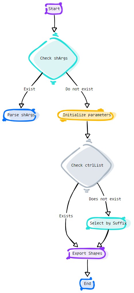
Purpose:
:: Exports control shapes from Autodesk Maya to a specified file, allowing for easy backup and reuse in different projects.
Essential for preserving custom control shapes and transferring them between scenes or Maya installations.
- Parameters:
filePath – <str, optional> # Path to the file where control shapes are to be exported.
fileName – <str, optional> # Name of the file for exporting control shapes.
ctrlList – <list, optional> # List of controls to export.
sufxList – <str, optional> # Suffix for the controls to be exported.
exFolder – <str, optional> # Folder for exporting the control shapes.
- Returns:
<str> # The path of the exported control shapes file.
Code Examples:
>>> export_path = "/path/to/export"
>>> export_file = "control_shapes"
>>> control_list = ["ctrl1", "ctrl2"]
>>> exportCtrlShapes(export_path, export_file, control_list)
# Exports control shapes of 'ctrl1' and 'ctrl2' to '/path/to/export/control_shapes_ctrlShapes.mel'.
Returns:
filePath + fileName + '_CtrlShapes.mel'
Usage:
if not ctrlList:
        try:
                mc.select ('*' + ctrlSufx, r=1)
                ctrlList =asN._selected()
        except:
                eRig.error('No Ctrls are selected with this suffix %s' %ctrlSufx)
graph TD Start[("fa:fa-play Start")] --> CheckShArgs{"/fas:fa-question-circle Check shArgs"} CheckShArgs --"If shArgs Exist"--> ParseShArgs["/fas:fa-cogs Parse shArgs"] CheckShArgs --"If shArgs Does Not Exist"--> InitializeParameters["/fas:fa-wrench Initialize Parameters"] InitializeParameters --> CheckCtrlList{"/fas:fa-check-square Check Control List"} CheckCtrlList --"If Control List Exists"--> ExportShapes["/fas:fa-upload Export Control Shapes"] CheckCtrlList --"If Control List Does Not Exist"--> SelectBySuffix["/fas:fa-filter Select by Suffix"] SelectBySuffix --> ExportShapes["/fas:fa-upload Export Control Shapes"] ExportShapes --> End["/fas:fa-stop End"] style Start fill:#00cc00,stroke:#000,stroke-width:3px style CheckShArgs fill:#ffcc00,stroke:#000,stroke-width:2px style ParseShArgs fill:#ff9999,stroke:#000,stroke-width:2px style InitializeParameters fill:#99ccff,stroke:#000,stroke-width:2px style CheckCtrlList fill:#cc99ff,stroke:#000,stroke-width:2px style ExportShapes fill:#99ff99,stroke:#000,stroke-width:2px style SelectBySuffix fill:#cc99ff,stroke:#000,stroke-width:2px style End fill:#ff6666,stroke:#000,stroke-width:3px- Flow Chart Description:
This flowchart illustrates the exportCtrlShapes function:
Checks if shArgs exist, and if so, parses the filePath, fileName, ctrlList, sufxList, and exFolder from it.
If shArgs do not exist, initializes parameters with default values.
Checks if the ctrlList exists.
If the ctrlList exists, exports control shapes from the specified controls.
If the ctrlList does not exist, selects controls by suffix and then exports their control shapes.
Ends the process.
- eCtrl.eyesCtrl(self, ctrlName=None, grpLevel=3, snapPiv=True, ctrlType=2, **shArgs)#
[shArgs : cn=ctrlName, gl=grpLevel, sp=snapPiv, ct=ctrlType]
Purpose:
:: Creates an eye control in Autodesk Maya, allowing for customized group levels, pivot snapping, and control types.
This function is essential for rigging eyes in characters, providing a simple way to manage eye movements.
The flexibility in control type and group hierarchy makes it suitable for different rigging requirements.
- Parameters:
ctrlName – <str, optional> # Name for the eye control. Defaults to None.
grpLevel – <int, optional> # Hierarchy level for grouping the control. Default is 3.
snapPiv – <bool, optional> # Determines if the control’s pivot should be snapped. Default is True.
ctrlType – <int, optional> # Type of eye control to create. Default is 2.
- Returns:
<list> # A list containing the control and its top group as Maya nodes, based on grpLevel.
Code Examples:
>>> control_name = "myEyeCtrl"
>>> control, control_group = eyesCtrl(ctrlName=control_name, ctrlType=1)
# Creates a type 1 eye control with the specified name.
graph TB Start[("fa:fa-play Start")] --> CheckCtrlName{{"/fas:fa-keyboard Check Control Name"}} CheckCtrlName --"CtrlName provided"--> DetermineCtrlType{{"/fas:fa-eye Determine Control Type"}} CheckCtrlName --"CtrlName not provided"--> AssignDefaultName[("/fas:fa-edit Assign Default Ctrl Name")] AssignDefaultName --> DetermineCtrlType DetermineCtrlType --"Type 1"--> CreateCtrlType1[("/fas:fa-circle Create Control Type 1")] DetermineCtrlType --"Type 2"--> CreateCtrlType2[("/fas:fa-circle-o Create Control Type 2")] CreateCtrlType1 --> DeleteHistory[("/fas:fa-eraser Delete History")] CreateCtrlType2 --> DeleteHistory DeleteHistory --> FinalizeCtrl[("/fas:fa-check-square Finalize Control")] FinalizeCtrl --> End[("fas:fa-stop-circle End")] style Start fill:#00cc00,stroke:#000,stroke-width:3px style CheckCtrlName fill:#ffcc00,stroke:#000,stroke-width:2px style AssignDefaultName fill:#99ff99,stroke:#000,stroke-width:2px style DetermineCtrlType fill:#ffcc00,stroke:#000,stroke-width:2px style CreateCtrlType1 fill:#99ccff,stroke:#000,stroke-width:2px style CreateCtrlType2 fill:#99ccff,stroke:#000,stroke-width:2px style DeleteHistory fill:#cc99ff,stroke:#000,stroke-width:2px style FinalizeCtrl fill:#cc99ff,stroke:#000,stroke-width:2px style End fill:#ff6666,stroke:#000,stroke-width:3px- Flow Chart Description:
This flowchart illustrates the eyesCtrl function:
The process starts by checking if a control name is provided. If not, a default name is assigned.
The function then determines the type of eye control to create, based on the ‘ctrlType’ parameter.
For Type 1, a specific eye control shape is created using circle and modification commands.
For Type 2, a different eye control shape is created using curve and closeCurve commands.
After creating the control, the function deletes any history attached to it.
The control is then finalized with group levels, pivot snapping, and color application.
The process ends by returning the control and its top group as Maya nodes.
- eCtrl.featherCtrl(self, ctrlName=None, prefixSide='L_', grpLevel=1, snapPiv=1, **shArgs)#
[shArgs : cn=ctrlName, ps=prefixSide, gl=grpLevel, sp=snapPiv]
Purpose:
:: Creates a feather control in Autodesk Maya, offering customization for side prefix, group level, and pivot snapping. :: Ideal for animating feathers or similar elements requiring delicate, articulated movements.
- Parameters:
ctrlName – (<str>, optional) # Name for the feather control.
prefixSide – (<str>, optional) # Side prefix for the control, typically ‘L_’ for left or ‘R_’ for right. Default is ‘L_’.
grpLevel – (<int>, optional) # Specifies the hierarchy level for grouping the control. Default is 1.
snapPiv – (<bool>, optional) # Determines if the control’s pivot should be snapped. Default is 1.
- Returns:
(<list>) # A list containing the control and its top group as Maya nodes, based on grpLevel.
Code Examples:
>>> control_name = "featherCtrl"
>>> side_prefix = "L_"
>>> group_level = 1
>>> snap_pivot = True
>>> ctrl, ctrl_grp = eCtrl.featherCtrl(control_name, side_prefix, group_level, snap_pivot)
# Creates a feather control with specified parameters.
graph TB Start[("fa:fa-play Start")] --> CheckPrefixSide{{"/fas:fa-check-circle Check Prefix Side"}} CheckPrefixSide --"Prefix Side 'L_' or 'LT_'"--> CreateCtrlL[("/fas:fa-plus-circle Create Ctrl 'L_'")] CheckPrefixSide --"Prefix Side 'R_' or 'RT_'"--> CreateCtrlR[("/fas:fa-plus-circle Create Ctrl 'R_'")] CreateCtrlL --> GroupCtrlL[("/fas:fa-object-group Group Ctrl 'L_'")] CreateCtrlR --> GroupCtrlR[("/fas:fa-object-group Group Ctrl 'R_'")] GroupCtrlL --> ApplyColorL[("/fas:fa-palette Apply Color to Ctrl 'L_'")] GroupCtrlR --> ApplyColorR[("/fas:fa-palette Apply Color to Ctrl 'R_'")] ApplyColorL --> End[("fas:fa-stop-circle End")] ApplyColorR --> End style Start fill:#00cc00,stroke:#000,stroke-width:3px style CheckPrefixSide fill:#ffcc00,stroke:#000,stroke-width:2px style CreateCtrlL fill:#ff9999,stroke:#000,stroke-width:2px style CreateCtrlR fill:#99ccff,stroke:#000,stroke-width:2px style GroupCtrlL fill:#99ff99,stroke:#000,stroke-width:2px style GroupCtrlR fill:#ff6666,stroke:#000,stroke-width:3px style ApplyColorL fill:#99ccff,stroke:#000,stroke-width:2px style ApplyColorR fill:#99ff99,stroke:#000,stroke-width:2px style End fill:#ff6666,stroke:#000,stroke-width:3px- Flow Chart Description:
This flowchart illustrates the featherCtrl function:
- eCtrl.finalizeCtrl(self, ctrl, initRot=[0, 0, 0], grpLevel=3, snapPiv=True, grpSufxList=None, colorVal=None, **shArgs)#
[**shArgs : c=ctrl, ir=initRot, gl=grpLevel, sp=snapPiv, gsl=grpSufxList, cv=colorVal]
Purpose:
:: Finalizes a control in Autodesk Maya, setting its initial rotation, group level, pivot snapping, group suffix, and color.
- Parameters:
node) (ctrl (Maya) – The control to be finalized.
optional) (colorVal (color,) – Initial rotation of the control, given as [x, y, z]. Default is [0, 0, 0].
optional) – The hierarchy level for the control’s grouping. Default is 3.
optional) – Whether to snap the control’s pivot. Default is True.
optional) – Suffix list for the control’s groups.
optional) – Color value to apply to the control.
- Returns:
None. The control is modified in place.
Code Examples:
>>> control_node = 'myCtrl'
>>> initialize_rotation = [90, 0, 0]
>>> group_level = 2
>>> snap_pivot = True
>>> finalizeCtrl(control_node, initialize_rotation, group_level, snap_pivot)
# Modifies ‘myCtrl’, sets its rotation, groups it and snaps its pivot as specified.
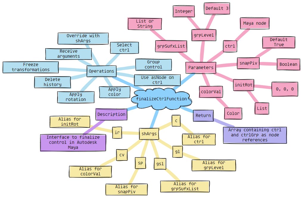
- eCtrl.fingerCtrl(self, ctrlName=None, grpLevel=1, ctrlType=1, snapPiv=1, initRot=[0, 0, 0], grpSufxList=None, **shArgs)#
[shArgs : cn=ctrlName, gl=grpLevel, ct=ctrlType, sp=snapPiv, ir=initRot, gsl=grpSufxList]
Purpose:
:: Creates a finger control in Autodesk Maya, allowing customization for group levels, control type, pivot snapping, initial rotation, and group suffix list. :: Useful for detailed rigging and animation of finger movements.
- Parameters:
ctrlName – (<str>, optional) # Name for the finger control.
grpLevel – (<int>, optional) # Specifies the hierarchy level for grouping the control. Default is 1.
ctrlType – (<int>, optional) # Type of the control to be created. Default is 1.
snapPiv – (<bool>, optional) # Determines if the control’s pivot should be snapped. Default is 1.
initRot – (<list>, optional) # Initial rotation of the control, given as [x, y, z]. Default is [0, 0, 0].
grpSufxList – (<list/str>, optional) # Suffix list for the control’s groups.
- Returns:
(<list>) # A list containing the control and its top group as Maya nodes, based on grpLevel.
Code Examples:
>>> control_name = "fingerCtrl"
>>> group_level = 1
>>> control_type = 1
>>> snap_pivot = True
>>> initial_rotation = [0, 0, 0]
>>> group_suffix_list = ["grp1", "grp2"]
>>> ctrl, ctrl_grp = eCtrl.fingerCtrl(control_name, group_level, control_type, snap_pivot, initial_rotation, group_suffix_list)
# Creates a finger control with specified parameters.
graph TB Start[("fa:fa-play Start")] --> CheckCtrlName{{"/fas:fa-check-circle Check Ctrl Name"}} CheckCtrlName --"If ctrlName is None"--> AssignDefaultName[("/fas:fa-pen Assign Default Name")] CheckCtrlName --"If ctrlName is provided"--> CreateCtrl[("/fas:fa-plus-circle Create Control")] AssignDefaultName --> CreateCtrl CreateCtrl --> ApplyInitRot[("/fas:fa-sync-alt Apply Initial Rotation")] ApplyInitRot --> FreezeCtrl[("/fas:fa-snowflake Freeze Control")] FreezeCtrl --> GroupCtrl[("/fas:fa-object-group Group Control")] GroupCtrl --> ApplyCtrlColor[("/fas:fa-palette Apply Control Color")] ApplyCtrlColor --> End[("fas:fa-stop-circle End")] style Start fill:#00cc00,stroke:#000,stroke-width:3px style CheckCtrlName fill:#ffcc00,stroke:#000,stroke-width:2px style AssignDefaultName fill:#ff9999,stroke:#000,stroke-width:2px style CreateCtrl fill:#99ccff,stroke:#000,stroke-width:2px style ApplyInitRot fill:#cc99ff,stroke:#000,stroke-width:2px style FreezeCtrl fill:#99ff99,stroke:#000,stroke-width:2px style GroupCtrl fill:#ff6666,stroke:#000,stroke-width:3px style ApplyCtrlColor fill:#99ccff,stroke:#000,stroke-width:2px style End fill:#ff6666,stroke:#000,stroke-width:3px- Flow Chart Description:
This flowchart illustrates the fingerCtrl function:
The process starts by checking if ctrlName is provided. If not, a default name is assigned.
The finger control is created based on the specified ctrlType.
Initial rotation (initRot) is applied to the control, and then the control is frozen to reset transformations.
The control is grouped according to the specified grpLevel and any suffixes provided in grpSufxList.
Control color is applied, and the function returns the control and its top group as Maya nodes.
- eCtrl.fistCtrl(self, ctrlName, grpLevel=1, ctrlType=1)#
[shArgs : cn=ctrlName, gl=grpLevel, ct=ctrlType]
Purpose:
:: Generates a fist control in Autodesk Maya, ideal for detailed rigging and animation of hand movements. :: Offers flexibility in the design and grouping of the control for complex character rigs.
- Parameters:
ctrlName – <str> # Required name for the fist control.
grpLevel – <int>, optional # Hierarchy level for grouping the control. Default is 1.
ctrlType – <int>, optional # Specifies the type of control to be created. Default is 1.
- Returns:
<list> # A list containing the control and its top group as Maya nodes, based on grpLevel.
Code Examples:
>>> control_name = "fistCtrl"
>>> group_level = 1
>>> control_type = 1
>>> ctrl, ctrl_grp = eCtrl.fistCtrl(control_name, group_level, control_type)
# Creates a fist control with specified parameters.
graph TB Start[("fa:fa-play Start")] --> CheckCtrlType{{"/fas:fa-check-circle Check Ctrl Type"}} CheckCtrlType --"Ctrl Type 1"--> CreateCtrl1[("/fas:fa-plus-circle Create Ctrl Type 1")] CheckCtrlType --"Ctrl Type 2"--> CreateCtrl2[("/fas:fa-plus-circle Create Ctrl Type 2")] CheckCtrlType --"Other Ctrl Types"--> CreateCtrlOther[("/fas:fa-plus-circle Create Other Ctrl Types")] CreateCtrl1 --> GroupCtrl1[("/fas:fa-object-group Group Ctrl Type 1")] CreateCtrl2 --> GroupCtrl2[("/fas:fa-object-group Group Ctrl Type 2")] CreateCtrlOther --> GroupCtrlOther[("/fas:fa-object-group Group Other Ctrl Types")] GroupCtrl1 --> ApplyColor1[("/fas:fa-palette Apply Color to Ctrl Type 1")] GroupCtrl2 --> ApplyColor2[("/fas:fa-palette Apply Color to Ctrl Type 2")] GroupCtrlOther --> ApplyColorOther[("/fas:fa-palette Apply Color to Other Ctrl Types")] ApplyColor1 --> End[("fas:fa-stop-circle End")] ApplyColor2 --> End ApplyColorOther --> End style Start fill:#00cc00,stroke:#000,stroke-width:3px style CheckCtrlType fill:#ffcc00,stroke:#000,stroke-width:2px style CreateCtrl1 fill:#ff9999,stroke:#000,stroke-width:2px style CreateCtrl2 fill:#99ccff,stroke:#000,stroke-width:2px style CreateCtrlOther fill:#cc99ff,stroke:#000,stroke-width:2px style GroupCtrl1 fill:#99ff99,stroke:#000,stroke-width:2px style GroupCtrl2 fill:#ff6666,stroke:#000,stroke-width:3px style GroupCtrlOther fill:#99ccff,stroke:#000,stroke-width:2px style ApplyColor1 fill:#99ccff,stroke:#000,stroke-width:2px style ApplyColor2 fill:#99ff99,stroke:#000,stroke-width:2px style ApplyColorOther fill:#ff6666,stroke:#000,stroke-width:3px style End fill:#ff6666,stroke:#000,stroke-width:3px- Flow Chart Description:
This flowchart illustrates the fistCtrl function:
The process begins by checking the ctrlType provided.
Based on the ctrlType, the corresponding control is created (Type 1, Type 2, or Other).
Each control type is then grouped according to grpLevel.
Finally, an appropriate color is applied to the control before the function ends.
- eCtrl.fkCtrl(self, ctrlName=None, prefixSide='L_', grpLevel=1, ctrlType=1, initRot=[0, 0, 0], snapPiv=1, ctrl3Axis='x', **shArgs)#
[shArgs : cn=ctrlName, ps=prefixSide, gl=grpLevel, ct=ctrlType, ir=initRot, sp=snapPiv, ca=ctrl3Axis]
Purpose:
:: Provides a method to create forward kinematics (FK) controls in Autodesk Maya, allowing customization for various rigging needs.
This function is essential for rigging characters, enabling the creation of FK controls that are tailored to specific requirements.
The flexibility in specifying parameters like control type, initial rotation, and pivot snapping enhances the rigging process.
- Parameters:
ctrlName – <str, optional> # Name for the FK control. It can be left as None for a default naming convention.
prefixSide – <str, optional> # Side prefix for the control, indicating left or right side. Defaults to ‘L_’.
grpLevel – <int, optional> # Group level for organizing the control within the hierarchy. Defaults to 1.
ctrlType – <int, optional> # Type of control shape to be created. Default value is 1.
initRot – <list, optional> # Initial rotation of the control, specified as [x, y, z]. Defaults to [0, 0, 0].
snapPiv – <bool, optional> # Indicates whether the pivot of the control should be snapped. Default is True (1).
ctrl3Axis – <str, optional> # Defines the 3-axis for the control. Default is ‘x’.
- Returns:
<list> # Returns a list containing the control and its top group as Maya nodes, based on the specified group level.
Code Examples:
>>> control_name = "myFKControl"
>>> control, control_group = fkCtrl(ctrlName=control_name, grpLevel=2, ctrlType=3)
# Creates an FK control with a box shape and 2 group levels.
graph TB Start[("fa:fa-play Start")] --> CheckCtrlName{{"/fas:fa-keyboard Check Control Name"}} CheckCtrlName --"CtrlName provided"--> CreateCtrlShape[("/fas:fa-pencil-square-o Create Control Shape")] CheckCtrlName --"CtrlName not provided"--> DefaultNaming[("/fas:fa-tag Default Naming")] DefaultNaming --> CreateCtrlShape CreateCtrlShape --> RotateCtrl[("/fas:fa-undo-alt Rotate Control")] RotateCtrl --> GroupControl[("/fas:fa-object-group Group Control")] GroupControl --> ApplyColor[("/fas:fa-paint-brush Apply Color")] ApplyColor --> End[("fas:fa-stop-circle End")] style Start fill:#00cc00,stroke:#000,stroke-width:3px style CheckCtrlName fill:#ffcc00,stroke:#000,stroke-width:2px style DefaultNaming fill:#ff9999,stroke:#000,stroke-width:2px style CreateCtrlShape fill:#99ccff,stroke:#000,stroke-width:2px style RotateCtrl fill:#cc99ff,stroke:#000,stroke-width:2px style GroupControl fill:#99ff99,stroke:#000,stroke-width:2px style ApplyColor fill:#ff6666,stroke:#000,stroke-width:3px style End fill:#ff6666,stroke:#000,stroke-width:3px- Flow Chart Description:
This flowchart illustrates the fkCtrl function:
The process starts by checking if a control name (ctrlName) is provided. If not, a default naming convention is applied.
The function then creates the FK control shape based on specified parameters like control type (ctrlType) and prefix side (prefixSide).
The control is rotated to its initial rotation (initRot) if specified.
The control is grouped based on the specified group level (grpLevel), and pivot snapping (snapPiv) is applied.
Finally, color is applied to the control for identification, and the process ends.
The function returns a list containing the FK control and its top group as Maya nodes.
- eCtrl.fkJntCtrl(self, jntList=None, ctrlNames=None, prefixSide='L_', grpLevel=4, ctrlType=4, initRot=[0, 0, 0], snapPiv=1, ctrl3Axis='x', jntSuffix='_Jnt', **shArgs)#
[shArgs : jl=jntList, cn=ctrlNames, ps=prefixSide, gl=grpLevel, ct=ctrlType, ir=initRot, sp=snapPiv, ca=ctrl3Axis, js=jntSuffix]
Purpose:
:: Facilitates the creation of FK controls for a series of joints in Autodesk Maya, offering a wide range of customization options for rigging.
Ideal for setting up FK rigs on characters or mechanical objects, providing riggers with the flexibility to adapt controls to specific joint chains.
The option to specify joint lists, control names, and various control types allows for precise and efficient rig creation.
- Parameters:
jntList – <list, optional> # List of joints for which FK controls are created. If None, selections are used.
ctrlNames – <list/str, optional> # Names to assign to the FK controls. Can be a single name or a list matching the joint list.
prefixSide – <str, optional> # Prefix indicating the side of the body (e.g., ‘L_’ for left). Defaults to ‘L_’.
grpLevel – <int, optional> # Specifies the hierarchy level for control grouping. Default is 4.
ctrlType – <int, optional> # Determines the shape and style of the FK control. Default is 4.
initRot – <list, optional> # Initial rotation of each control in [x, y, z] format. Default is [0, 0, 0].
snapPiv – <bool, optional> # Whether to snap the pivot of the control to the joint. Default is True.
ctrl3Axis – <str, optional> # Defines the 3-axis direction for the control. Default is ‘x’.
jntSuffix – <str, optional> # Suffix used in joint names. Default is ‘_Jnt’.
- Returns:
<list> # A list of created FK controls and their group nodes, providing a structured rig setup.
Code Examples:
>>> joint_names = ["joint1", "joint2", "joint3"]
>>> control_names = ["ctrl1", "ctrl2", "ctrl3"]
>>> fk_controls = fkJntCtrl(jntList=joint_names, ctrlNames=control_names, grpLevel=3, ctrlType=2)
# Creates FK controls for specified joints with designated control names and properties.
Updates:
1. Support for Multiple joints
2. Orientation of control based on joint dir
graph TB Start[("fa:fa-play Start")] --> CheckJntList{{"/fas:fa-project-diagram Check Joint List"}} CheckJntList --"JntList provided"--> IterateJoints[("/fas:fa-list-ol Iterate Joints")] CheckJntList --"JntList not provided"--> SelectJoints[("/fas:fa-mouse-pointer Select Joints")] SelectJoints --> IterateJoints IterateJoints --> CheckJntType{{"/fas:fa-bone Check Joint Type"}} CheckJntType --"Is Joint"--> CreateFkCtrl[("/fas:fa-plus-square Create FK Control")] CheckJntType --"Not a Joint"--> SkipJnt[("/fas:fa-forward Skip Joint")] SkipJnt --> IterateJoints CreateFkCtrl --> SetCtrlScale[("/fas:fa-expand-arrows-alt Set Control Scale")] SetCtrlScale --> PositionCtrl[("/fas:fa-map-pin Position Control")] PositionCtrl --> ConstrainToJnt[("/fas:fa-link Constrain to Joint")] ConstrainToJnt --> LockCtrlAttrs[("/fas:fa-lock Lock Control Attributes")] LockCtrlAttrs --> End[("fas:fa-stop-circle End")] style Start fill:#00cc00,stroke:#000,stroke-width:3px style CheckJntList fill:#ffcc00,stroke:#000,stroke-width:2px style SelectJoints fill:#ff9999,stroke:#000,stroke-width:2px style IterateJoints fill:#99ccff,stroke:#000,stroke-width:2px style CheckJntType fill:#cc99ff,stroke:#000,stroke-width:2px style CreateFkCtrl fill:#99ff99,stroke:#000,stroke-width:2px style SetCtrlScale fill:#ff6666,stroke:#000,stroke-width:3px style PositionCtrl fill:#ffcc00,stroke:#000,stroke-width:2px style ConstrainToJnt fill:#ff9999,stroke:#000,stroke-width:2px style LockCtrlAttrs fill:#99ccff,stroke:#000,stroke-width:2px style End fill:#ff6666,stroke:#000,stroke-width:3px- Flow Chart Description:
This flowchart illustrates the fkJntCtrl function:
The process starts by checking if a joint list (jntList) is provided. If not, joints are selected.
The function iterates through each joint in the list.
For each joint, it checks if the node is a valid joint.
If it’s a joint, an FK control is created with the specified properties like control type (ctrlType) and side prefix (prefixSide).
The control is scaled to match the joint size and positioned at the joint location.
The control is then constrained to the joint for FK animation.
Attributes like scale and visibility are locked on the control to finalize the setup.
The process repeats for each joint in the list, and the function returns a list of all created FK controls and groups.
- eCtrl.footCtrl(self, ctrlName=None, sidePos='L_', grpLevel=3, ctrlType=1, initRot=None, colorVal=None, **shArgs)#
[**shArgs : cn=ctrlName, sp=sidePos, gl=grpLevel, ct=ctrlType, ir=initRot, cv=colorVal]
Purpose:
:: Generates a foot control in Autodesk Maya with options for side position, group level, control type, initial rotation, and color. :: Ideal for rigging and animation in character setup, especially for feet controls.
- Parameters:
ctrlName – (<str>, optional) # Name for the foot control. If not provided, defaults to ‘as_Foot_Ctrl’.
sidePos – (<str>, optional) # Side position for the control, ‘L_’ for left or ‘R_’ for right. Default is ‘L_’.
grpLevel – (<int>, optional) # Hierarchy level for grouping the control. Default is 3.
ctrlType – (<int>, optional) # Type of foot control to be created (1: Generic, 2: Human, 3: Bird).
initRot – (<list>, optional) # Initial rotation of the control, given as [x, y, z].
colorVal – (<color>, optional) # Color value to apply to the control.
- Returns:
(<list>) # Returns [ctrl, ctrlGrp(topGrp)] as Maya nodes, based on grpLevel.
Code Examples:
>>> ctrl_name = "myFootCtrl"
>>> side_position = "L_"
>>> group_level = 3
>>> control_type = 1
>>> initial_rotation = [0, 90, 0]
>>> color_value = "blue"
>>> ctrl, ctrl_grp = eCtrl.footCtrl(ctrl_name, side_position, group_level, control_type, initial_rotation, color_value)
# Creates a left foot control with specified parameters.
graph TB Start[("fa:fa-play Start")] --> CheckCtrlName{{"/fas:fa-question-circle Check Control Name"}} CheckCtrlName --"If ctrlName is provided"--> CreateCtrl[("/fas:fa-circle Create Control")] CheckCtrlName --"If ctrlName is not provided"--> AssignDefaultName[("/fas:fa-pencil-alt Assign Default Name")] AssignDefaultName --> CreateCtrl CreateCtrl --> CheckCtrlType{{"/fas:fa-sitemap Check Control Type"}} CheckCtrlType --"Type 1"--> CreateType1[("/fas:fa-shoe-prints Create Type 1 Control")] CheckCtrlType --"Type 2"--> CreateType2[("/fas:fa-shoe-prints Create Type 2 Control")] CheckCtrlType --"Type 3"--> CreateType3[("/fas:fa-shoe-prints Create Type 3 Control")] CheckCtrlType --"Type 4"--> CreateType4[("/fas:fa-shoe-prints Create Type 4 Control")] CreateType1 --> FinalizeCtrl[("/fas:fa-check-circle Finalize Control")] CreateType2 --> FinalizeCtrl CreateType3 --> FinalizeCtrl CreateType4 --> FinalizeCtrl FinalizeCtrl --> ApplyCtrlColor[("/fas:fa-palette Apply Control Color")] ApplyCtrlColor --> GroupCtrl[("/fas:fa-object-group Group Control")] GroupCtrl --> End[("fas:fa-stop-circle End")] style Start fill:#00cc00,stroke:#000,stroke-width:3px style CheckCtrlName fill:#ffcc00,stroke:#000,stroke-width:2px style AssignDefaultName fill:#ff9999,stroke:#000,stroke-width:2px style CreateCtrl fill:#99ccff,stroke:#000,stroke-width:2px style CheckCtrlType fill:#cc99ff,stroke:#000,stroke-width:2px style CreateType1 fill:#99ff99,stroke:#000,stroke-width:2px style CreateType2 fill:#ff6666,stroke:#000,stroke-width:3px style CreateType3 fill:#99ccff,stroke:#000,stroke-width:2px style CreateType4 fill:#cc99ff,stroke:#000,stroke-width:2px style FinalizeCtrl fill:#99ff99,stroke:#000,stroke-width:2px style ApplyCtrlColor fill:#ffcc00,stroke:#000,stroke-width:2px style GroupCtrl fill:#ff9999,stroke:#000,stroke-width:2px style End fill:#ff6666,stroke:#000,stroke-width:3px- Flow Chart Description:
This flowchart illustrates the footCtrl function:
The process begins by checking if a control name (ctrlName) is provided. If not, a default name is assigned.
The control type (ctrlType) determines the shape and style of the foot control.
Depending on the control type, one of four different foot control shapes is created.
The control is finalized, which includes applying color and grouping based on the specified group level (grpLevel).
The function concludes by returning the control and its top group as Maya nodes.
- eCtrl.footEndCtrl(self, ctrlName=None, grpLevel=3, initRot=[0, 0, 0], ctrlType=1, grpSufxList=None, **shArgs)#
[shArgs : cn=ctrlName, gl=grpLevel, ct=ctrlType, ir=initRot, sp=snapPiv, gsl=grpSufxList, cv=colorVal]
Purpose:
:: Creates a foot end control in Autodesk Maya, offering customization for control name, group level, control type, initial rotation, pivot snapping, group suffix list, and color value.
Ideal for rigging foot mechanisms in character animation, providing precise control over foot movements.
Offers flexibility in control design to match specific rigging requirements.
- Parameters:
ctrlName – <str, optional> #Name for the foot end control. Defaults to None, which assigns a default name.
grpLevel – <int, optional> #Hierarchy level for grouping the control. Defaults to 3.
initRot – <list, optional> #Initial rotation of the control, given as [x, y, z]. Defaults to [0, 0, 0].
ctrlType – <int, optional> #Specifies the type of foot end control to create. Options include different shapes. Defaults to 1.
grpSufxList – <list/str, optional> #Suffix list for the control’s groups.
colorVal – <color, optional> #Color value to apply to the control.
- Returns:
<list> #A list containing the control and its top group as Maya nodes, based on grpLevel.
Code Examples:
>>> ctrl_name = "footEndCtrl"
>>> group_level = 3
>>> initial_rotation = [0, 45, 0]
>>> control_type = 1
>>> group_suffix_list = ["_grp1", "_grp2"]
>>> color_value = 6
>>> foot_end_ctrl, foot_end_grp = footEndCtrl(ctrl_name, group_level, initial_rotation, control_type, group_suffix_list, color_value)
graph TB Start[("fa:fa-play Start")] --> CheckInputs{"/fas:fa-question-circle Check Inputs"} CheckInputs --"Input Provided"--> CreateControl[("/fas:fa-shoe-prints Create Foot End Control")] CreateControl --> GroupControl[("/fas:fa-object-group Group Control")] GroupControl --> ApplyColor[("/fas:fa-palette Apply Color")] ApplyColor --> End[("fas:fa-stop-circle End")] CheckInputs --"No Input"--> Error[("fa:fa-times Error")] style Start fill:#00cc00,stroke:#000,stroke-width:3px style CheckInputs fill:#ffcc00,stroke:#000,stroke-width:2px style CreateControl fill:#99ff99,stroke:#000,stroke-width:2px style GroupControl fill:#ff9999,stroke:#000,stroke-width:2px style ApplyColor fill:#99ccff,stroke:#000,stroke-width:2px style Error fill:#ff6666,stroke:#000,stroke-width:3px style End fill:#ff6666,stroke:#000,stroke-width:3px- Flow Chart Description:
This flowchart illustrates the footEndCtrl function:
The process starts by checking if the necessary inputs are provided for creating a foot end control. These include control name, group level, initial rotation, control type, group suffix list, and color value.
If the inputs are provided, a foot end control is created based on the specified parameters.
The control is then grouped according to the specified hierarchy level.
A color is applied to the control for visual differentiation and ease of use.
The process concludes successfully after the control is created and configured.
In the absence of necessary inputs, an error is indicated, and the process terminates.
- eCtrl.gearCtrl(self, ctrlName=None, grpLevel=3, ctrlType=2, initRot=[0, 0, 0], snapPiv=1, grpSufxList=None, colorVal=None, **shArgs)#
[**shArgs : cn=ctrlName, gl=grpLevel, ct=ctrlType, ir=initRot, sp=snapPiv, gsl=grpSufxList, cv=colorVal]
Purpose:
:: Creates a gear-shaped control in Autodesk Maya, with customizable group level, control type, initial rotation, pivot snapping, group suffix list, and color.
Useful for creating visually distinct controls in rigging and animation.
Provides options for initial orientation, pivot snapping, and control coloring for better rigging workflow.
- Parameters:
ctrlName – <str, optional> # Name for the gear control. Default is ‘as_Gear_Ctrl’ if not specified.
grpLevel – <int, optional> # Hierarchy level for grouping the control. Defaults to 3.
ctrlType – <int, optional> # Type of gear control to create, with different shapes corresponding to different integers.
initRot – <list, optional> # Initial rotation of the control as [x, y, z] values. Defaults to [0, 0, 0].
snapPiv – <bool, optional> # Whether to snap the control’s pivot to a specific point. Defaults to True.
grpSufxList – <list/str, optional> # Suffix list for the control’s groups.
colorVal – <color, optional> # Color value to apply to the control for visual differentiation.
- Returns:
<list> # A list containing the control and its top group as Maya nodes, depending on grpLevel.
Code Examples:
>>> control_name = "myGearCtrl"
>>> group_level = 2
>>> control_type = 1
>>> initial_rotation = [45, 0, 0]
>>> gear_control = gearCtrl(control_name, group_level, control_type, initial_rotation)
# Creates a gear-shaped control with specified parameters.
graph TB Start[("fa:fa-play Start")] --> CheckInputs{"/fas:fa-question-circle Check Inputs"} CheckInputs --"If shArgs Exist"--> ParseShArgs["/fas:fa-cogs Parse shArgs"] CheckInputs --"If shArgs Does Not Exist"--> InitializeParameters["/fas:fa-wrench Initialize Parameters"] ParseShArgs --> CreateGearControl[("/fas:fa-cog Create Gear Control")] InitializeParameters --> CreateGearControl CreateGearControl --> FinalizeControl[("/fas:fa-check-circle Finalize Control")] FinalizeControl --"Finalize Control with Parameters"--> End[("fas:fa-stop-circle End")] style Start fill:#00cc00,stroke:#000,stroke-width:3px style CheckInputs fill:#ffcc00,stroke:#000,stroke-width:2px style ParseShArgs fill:#ff9999,stroke:#000,stroke-width:2px style InitializeParameters fill:#99ccff,stroke:#000,stroke-width:2px style CreateGearControl fill:#99ff99,stroke:#000,stroke-width:2px style FinalizeControl fill:#ffcc99,stroke:#000,stroke-width:2px style End fill:#ff6666,stroke:#000,stroke-width:3px- Flow Chart Description:
This flowchart illustrates the gearCtrl function:
The function begins by checking if shArgs are provided. If they are, it parses arguments like ctrlName, grpLevel, ctrlType, initRot, snapPiv, grpSufxList, and colorVal.
If shArgs are not provided, it initializes parameters with default or provided values.
Creates a gear-shaped control based on the specified or default parameters.
Finalizes the control by applying initial rotation, group level, pivot snapping, group suffix list, and color value.
The function concludes after successfully creating and finalizing the gear control.
- eCtrl.generateCurvCMD(self, curvName='as_Curv', deg=3, step=1, objOrPosList=[], showCVs=True, showEditor=False, printCommand=True, **shArgs)#
[**shArgs : cn=curvName, d=deg, s=step, op=objOrPosList, sc=showCVs, se=showEditor, pc=printCommand]
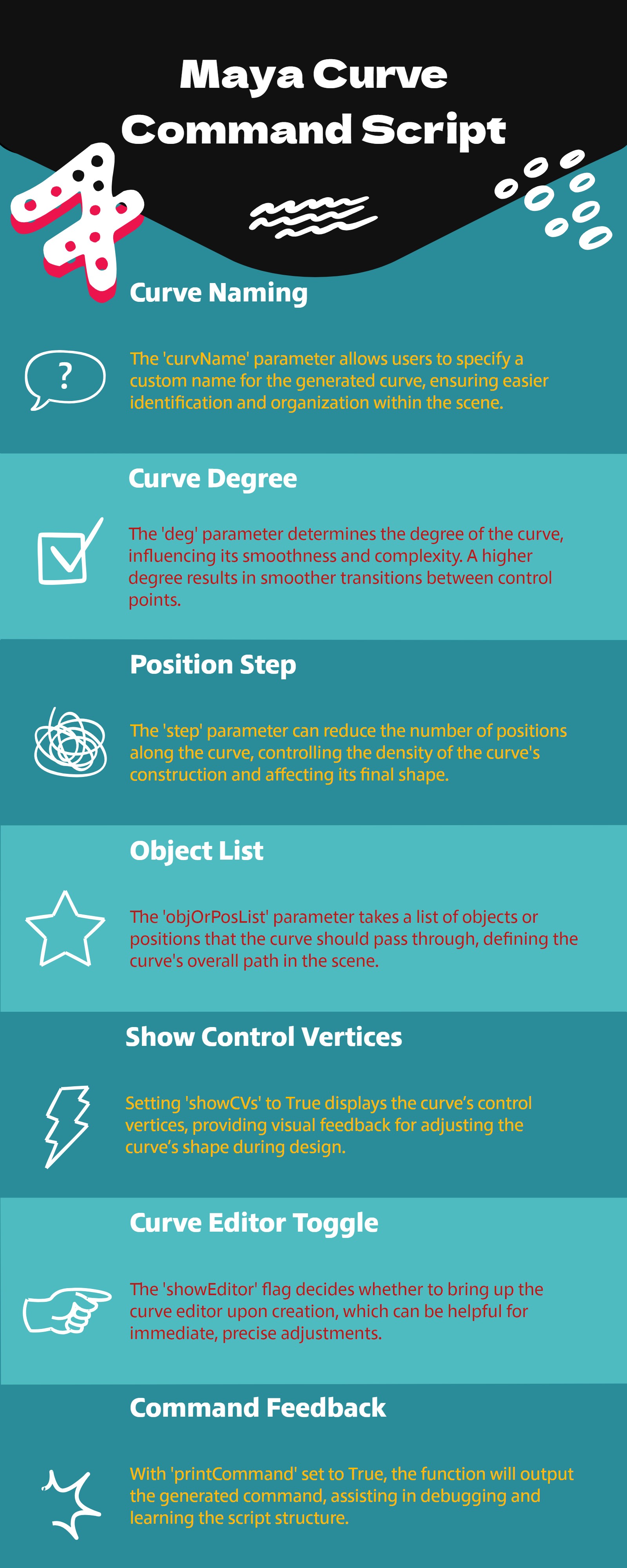
Purpose:
:: Generates a curve command in Autodesk Maya, allowing for detailed customization of curve degree, step, object or position list, and display options.
Ideal for script-based curve creation and manipulation.
Offers flexibility in defining curve characteristics and visualization.
- Parameters:
curvName – <str, optional> # Name for the curve. Default is ‘as_Curv’.
deg – <int, optional> # Degree of the curve. Default is 3.
step – <int, optional> # Step value for the curve. Default is 1.
objOrPosList – <list, optional> # List of objects or positions to define the curve.
showCVs – <bool, optional> # Whether to display the curve’s control vertices (CVs). Default is True.
showEditor – <bool, optional> # Whether to show the curve editor. Default is False.
printCommand – <bool, optional> # Whether to print the curve command. Default is True.
- Returns:
None # The command generates a curve in the Maya scene.
Code Examples:
>>> curve_name = "customCurve"
>>> degree = 3
>>> step_value = 2
>>> obj_list = ["obj1", "obj2"]
>>> generateCurvCMD(curve_name, degree, step_value, obj_list)
# Generates a custom curve based on the specified parameters.
graph TB Start[("fa:fa-play Start")] --> CheckInputs{"/fas:fa-question-circle Check Inputs"} CheckInputs --"Input Provided"--> ProcessInput[("/fas:fa-cogs Process Input")] ProcessInput --> GenerateCurve[("/fas:fa-spline Generate Curve Command")] GenerateCurve --> ExecuteCommand[("/fas:fa-terminal Execute Command")] ExecuteCommand --> End[("fas:fa-stop-circle End")] CheckInputs --"No Input"--> Error[("fa:fa-times Error")] style Start fill:#00cc00,stroke:#000,stroke-width:3px style CheckInputs fill:#ffcc00,stroke:#000,stroke-width:2px style ProcessInput fill:#99ff99,stroke:#000,stroke-width:2px style GenerateCurve fill:#ff9999,stroke:#000,stroke-width:2px style ExecuteCommand fill:#99ccff,stroke:#000,stroke-width:2px style Error fill:#ff6666,stroke:#000,stroke-width:3px style End fill:#ff6666,stroke:#000,stroke-width:3px- Flow Chart Description:
This flowchart illustrates the generateCurvCMD function:
The function begins by checking if all necessary inputs are provided.
If inputs are provided, it processes them to create a curve command.
The curve command is generated based on the input parameters.
The command is then executed to create the curve in Maya.
The function concludes after successfully executing the curve command.
If any inputs are missing, an error is indicated.
- eCtrl.getCurv_FromEdgeLoop(self, deg=3)#
[**shArgs : d=deg]
Purpose:
:: Extracts a curve from an edge loop in Autodesk Maya, converting a polygon edge loop into a NURBS curve.
Ideal for creating curves from existing polygon edge loops.
Allows for easy conversion of complex edge geometry to smooth curves.
- Parameters:
deg – <int, optional> # Degree of the curve to be created from the edge loop. Defaults to 3.
- Returns:
<str> # The name of the newly created curve as a Maya node.
Code Examples:
>>> degree = 3
>>> curve_name = getCurv_FromEdgeLoop(degree)
# Generates a NURBS curve from an edge loop with the specified degree.
graph TB Start[("fa:fa-play Start")] --> GetSelectedEdges{"/fas:fa-mouse-pointer Get Selected Edges"} GetSelectedEdges --"Selected Edges Exist"--> ConvertEdgesToCurve[("/fas:fa-random Convert Edges to Curve")] ConvertEdgesToCurve --"Conversion Successful"--> FinalizeCurve[("/fas:fa-check-circle Finalize Curve")] GetSelectedEdges --"No Edges Selected"--> Error[("fa:fa-times Error")] FinalizeCurve --"Curve Finalized"--> End[("fas:fa-stop-circle End")] style Start fill:#00cc00,stroke:#000,stroke-width:3px style GetSelectedEdges fill:#ffcc00,stroke:#000,stroke-width:2px style ConvertEdgesToCurve fill:#99ff99,stroke:#000,stroke-width:2px style FinalizeCurve fill:#ffcc99,stroke:#000,stroke-width:2px style Error fill:#ff6666,stroke:#000,stroke-width:3px style End fill:#ff6666,stroke:#000,stroke-width:3px- Flow Chart Description:
This flowchart illustrates the getCurv_FromEdgeLoop function:
Starts by getting the currently selected edges in Maya.
If edges are selected, it converts these edges into a NURBS curve with the specified degree.
Once the curve is created, it finalizes the curve by deleting history and centering its pivot.
If no edges are selected, an error is indicated.
The function concludes after the curve is finalized or if an error occurs due to no selection.
- eCtrl.getKnots(self, crvShape=None)#
[**shArgs : cs=crvShape]
Purpose:
:: Retrieves the knot values of a specified NURBS curve shape in Autodesk Maya.
Useful for detailed curve editing and manipulation.
Provides essential data for advanced rigging and animation techniques.
- Parameters:
crvShape – <str, optional> # Name of the curve shape whose knots are to be retrieved.
- Returns:
<list> # A list of knot values for the specified curve shape.
Code Examples:
>>> curve_shape = "curveShape1"
>>> knot_values = getKnots(curve_shape)
# Retrieves the knot values of the specified NURBS curve shape.
graph TB Start[("fa:fa-play Start")] --> CheckCurveShape{"/fas:fa-question-circle Check Curve Shape"} CheckCurveShape --"Curve Shape Provided"--> RetrieveKnots[("/fas:fa-cogs Retrieve Knots")] RetrieveKnots --"Knots Retrieved"--> End[("fas:fa-stop-circle End")] CheckCurveShape --"No Curve Shape Provided"--> Error[("fa:fa-times Error")] style Start fill:#00cc00,stroke:#000,stroke-width:3px style CheckCurveShape fill:#ffcc00,stroke:#000,stroke-width:2px style RetrieveKnots fill:#99ff99,stroke:#000,stroke-width:2px style Error fill:#ff6666,stroke:#000,stroke-width:3px style End fill:#ff6666,stroke:#000,stroke-width:3px- Flow Chart Description:
This flowchart illustrates the getKnots function:
The function starts by checking if a curve shape name is provided.
If a curve shape is provided, it retrieves the knot values of the specified NURBS curve shape.
If no curve shape is provided, an error is indicated.
The function concludes after retrieving the knot values or if an error occurs due to the absence of a curve shape.
- eCtrl.getShape(self, curv=None)#
[**shArgs : c=curv]
Purpose:
:: Returns a dictionary containing all necessary information for rebuilding a specified curve in Autodesk Maya.
Essential for curve duplication and reconstruction.
Provides comprehensive details for curve attributes and geometry.
- Parameters:
curv – <str, optional> # Name of the curve to retrieve shape information from.
- Returns:
<list> # A list of dictionaries, each containing detailed attributes of the curve shapes.
Code Examples:
>>> curve_name = "myCurve"
>>> shape_data = getShape(curve_name)
# Extracts detailed shape information from the specified curve.
graph TB Start[("fa:fa-play Start")] --> CheckCurveName{"/fas:fa-question-circle Check Curve Name"} CheckCurveName --"Curve Name Provided"--> RetrieveShapeData[("/fas:fa-cogs Retrieve Shape Data")] RetrieveShapeData --"Shape Data Retrieved"--> End[("fas:fa-stop-circle End")] CheckCurveName --"No Curve Name Provided"--> Error[("fa:fa-times Error")] style Start fill:#00cc00,stroke:#000,stroke-width:3px style CheckCurveName fill:#ffcc00,stroke:#000,stroke-width:2px style RetrieveShapeData fill:#99ff99,stroke:#000,stroke-width:2px style Error fill:#ff6666,stroke:#000,stroke-width:3px style End fill:#ff6666,stroke:#000,stroke-width:3px- Flow Chart Description:
This flowchart illustrates the getShape function:
The function starts by checking if a curve name is provided.
If a curve name is provided, it retrieves detailed shape information from the specified curve.
If no curve name is provided, an error is indicated.
The function concludes after retrieving the shape information or if an error occurs due to the absence of a curve name.
- eCtrl.globalCtrl(self, ctrlName, grpLevel=1, ctrlType=1, **shArgs)#
[**shArgs : cn=ctrlName, gl=grpLevel, ct=ctrlType]
Purpose:
:: Creates a global control in Autodesk Maya, offering options for control name, group level, and control type.
Useful for setting up master controls in rigging.
Customizable for various rigging and animation needs.
- Parameters:
ctrlName – <str> # Name for the global control.
grpLevel – <int, optional> # Hierarchy level for grouping the control. Default is 1.
ctrlType – <int, optional> # Type of global control to be created. Default is 1.
- Returns:
<list> # A list containing the control and its top group as Maya nodes, based on grpLevel.
Code Examples:
>>> control_name = "globalCtrl"
>>> group_level = 2
>>> control_type = 1
>>> global_control = globalCtrl(control_name, group_level, control_type)
# Creates a global control with specified parameters.
graph TB Start[("fa:fa-play Start")] --> CheckInputs{"/fas:fa-question-circle Check Inputs"} CheckInputs --"Input Provided"--> CreateControl[("/fas:fa-vector-square Create Global Control")] CreateControl --> GroupControl[("/fas:fa-object-group Group Control")] GroupControl --> ApplyColor[("/fas:fa-palette Apply Color")] ApplyColor --> End[("fas:fa-stop-circle End")] CheckInputs --"No Input"--> Error[("fa:fa-times Error")] style Start fill:#00cc00,stroke:#000,stroke-width:3px style CheckInputs fill:#ffcc00,stroke:#000,stroke-width:2px style CreateControl fill:#99ff99,stroke:#000,stroke-width:2px style GroupControl fill:#ff9999,stroke:#000,stroke-width:2px style ApplyColor fill:#99ccff,stroke:#000,stroke-width:2px style Error fill:#ff6666,stroke:#000,stroke-width:3px style End fill:#ff6666,stroke:#000,stroke-width:3px- Flow Chart Description:
This flowchart illustrates the globalCtrl function:
The function starts by checking if all necessary inputs like control name, group level, and control type are provided.
If inputs are provided, it creates a global control with the specified parameters.
The control is then grouped according to the hierarchy level specified.
Color is applied to the control for visual differentiation.
The function ends after successfully creating and configuring the global control.
If any inputs are missing, an error is indicated.
- eCtrl.headCtrl(self, ctrlName, grpLevel=1, ctrlType=1, snapPiv=False, **shArgs)#
[shArgs : cn=ctrlName, gl=grpLevel, ct=ctrlType, sp=snapPiv]
Purpose:
:: Creates a control in Autodesk Maya for animating a character’s head, providing customization in terms of grouping, control type, and pivot snapping.
The function allows for the creation of head controls with various shapes and functionalities.
It provides options to define the number of group levels, control type for different shapes, and whether to snap the pivot or not.
- Parameters:
ctrlName – <str> # The name to be assigned to the control.
grpLevel – <int> # The number of top groups on the control. Determines the hierarchical level.
ctrlType – <int> # The type of control to be created. 1 for standard head control, 2 for an alternative shape.
snapPiv – <bool> # Determines whether the groups’ pivot should be snapped to the control or not.
- Returns:
<list> # Returns a list of nodes, typically including the control and its top group.
Code Examples:
>>> control_name = "headControl"
>>> group_level = 1
>>> control_type = 1
>>> snap_pivot = True
>>> head_ctrl = headCtrl(control_name, group_level, control_type, snap_pivot)
# This will create a head control with specified parameters.
graph TB Start[("fa:fa-play Start")] --> CheckCtrlType{{"/fas:fa-shapes Check Control Type"}} CheckCtrlType --"Type 1"--> Type1[("/fas:fa-cube Create Head Control Type 1")] CheckCtrlType --"Type 2"--> Type2[("/fas:fa-sitemap Create Head Control Type 2")] Type1 --> FinalizeCtrl[("/fas:fa-check-square Finalize Control")] Type2 --> FinalizeCtrl FinalizeCtrl --> End[("fas:fa-stop-circle End")] style Start fill:#00cc00,stroke:#000,stroke-width:3px style CheckCtrlType fill:#ffcc00,stroke:#000,stroke-width:2px style Type1 fill:#99ff99,stroke:#000,stroke-width:2px style Type2 fill:#cc99ff,stroke:#000,stroke-width:2px style FinalizeCtrl fill:#cc99ff,stroke:#000,stroke-width:2px style End fill:#ff6666,stroke:#000,stroke-width:3px- Flow Chart Description:
This flowchart illustrates the headCtrl function:
The process begins by determining the type of head control to create.
If Type 1 is selected, a standard head control shape is created.
If Type 2 is selected, an alternative head control shape is created.
The function then finalizes the control with group levels, pivot snapping, and color application.
The process concludes by returning the control and its top group.
- eCtrl.ikCtrl(self, ctrlName=None, prefixSide='L_', grpLevel=1, ctrlType=1, snapPiv=1, initRot=[0, 0, 0], **shArgs)#
[**shArgs : cn=ctrlName, ps=prefixSide, gl=grpLevel, ct=ctrlType, sp=snapPiv, ir=initRot]
Purpose:
:: Creates an inverse kinematics (IK) control in Autodesk Maya, offering customization for control name, side prefix, group level, control type, pivot snapping, and initial rotation.
- Parameters:
ctrlName – (<str, Optional>) # Name for the IK control.
prefixSide – (<str, Optional>) # Side prefix for the control, typically ‘L_’ for left or ‘R_’ for right. Default is ‘L_’.
grpLevel – (<int, Optional>) # Hierarchy level for grouping the control. Default is 1.
ctrlType – (<int, Optional>) # Type of IK control to be created. Default is 1.
snapPiv – (<bool, Optional>) # Determines if the control’s pivot should be snapped. Default is True.
initRot – (<list, Optional>) # Initial rotation of the control, given as [x, y, z]. Default is [0, 0, 0].
- Returns:
(<list>) # A list containing the control and its top group as Maya nodes, based on grpLevel.
Example Usage:
>>> ctrlName = "myIKControl"
>>> prefixSide = "L_"
>>> grpLevel = 2
>>> ctrlType = 2
>>> snapPiv = True
>>> initRot = [45, 0, 0]
>>> ikCtrl(ctrlName, prefixSide, grpLevel, ctrlType, snapPiv, initRot)
# Create an IK control with the specified parameters.

ctrl              =eCtrl.ikCtrl(ctrlName)[0]
ctrlGrp           =eCtrl.ikCtrl(ctrlName)[-1]
ctrl, ctrlGrp =eCtrl.ikCtrl(ctrlName)
Returns:
if grpLevel:
        return [ctrl, ctrlGrp(topGrp)]  #_ asNodes
else:
        return [ctrl, ctrl]                     #_ asNodes
graph TB Start[("fa:fa-play Start")] --> CheckShArgs{"/fas:fa-question-circle Check shArgs"} CheckShArgs --"If shArgs Exist"--> InitializeParameters{"/fas:fa-wrench Initialize Parameters"} CheckShArgs --"If shArgs Does Not Exist"--> CheckCtrlName{"/fas:fa-check-square Check ctrlName"} InitializeParameters --> GetSelectedObjects{"/fas:fa-check-square Get Selected Objects"} CheckCtrlName --"If ctrlName is None"--> CreateDefaultCtrlName{"/fas:fa-check-square Create Default ctrlName"} CheckCtrlName --"If ctrlName is Not None"--> CheckPrefix{"/fas:fa-question-circle Check Prefix"} CreateDefaultCtrlName --> CreateDefaultCtrlName{"/fas:fa-wrench Create Default ctrlName"} CheckPrefix --"If Object Starts With Prefix"--> SplitObjectName{"/fas:fa-arrow-right Split Object Name"} CheckPrefix --"If Prefix is Found in Object"--> ReplacePrefix{"/fas:fa-arrows Replace Prefix"} CheckPrefix --"If No Prefix is Found"--> ErrorNoPrefix{"/fas:fa-exclamation-triangle Error: No Prefix Found"} SplitObjectName --> CheckObjectExists{"/fas:fa-question-circle Check Object Exists"} ReplacePrefix --> CheckObjectExists ErrorNoPrefix --> End{"/fas:fa-stop End"} CheckObjectExists --"If Target Object Exists"--> CreateCurves{"/fas:fa-pencil-alt Create Curves"} CheckObjectExists --"If Target Object Does Not Exist"--> ErrorObjectNotFound{"/fas:fa-exclamation-triangle Error: Target Object Not Found"} CreateCurves --"Create IK Control Curves"--> SelectCtrl{"/fas:fa-mouse-pointer Select Control"} SelectCtrl --> RotateControl{"/fas:fa-sync-alt Rotate Control"} RotateControl --"Rotate Control"--> FreezeControl{"/fas:fa-snowflake Freeze Control Transformation"} FreezeControl --"Freeze Control Transformation"--> GroupControl{"/fas:fa-sitemap Group Control with Hierarchy Level"} GroupControl --"Group Control with Hierarchy Level"--> ApplyControlColor{"/fas:fa-tint Apply Control Color"} ApplyControlColor --"Apply Control Color"--> ReturnResult{"/fas:fa-check Return Control and Group"} ReturnResult --"Return Control and Group"--> End{"/fas:fa-stop End"} style Start fill:#00cc00,stroke:#000,stroke-width:3px style CheckShArgs fill:#ffcc00,stroke:#000,stroke-width:2px style InitializeParameters fill:#99ccff,stroke:#000,stroke-width:2px style CheckCtrlName fill:#99ff99,stroke:#000,stroke-width:2px style CreateDefaultCtrlName fill:#ccffcc,stroke:#000,stroke-width:2px style CheckPrefix fill:#99ff99,stroke:#000,stroke-width:2px style SplitObjectName fill:#ccffcc,stroke:#000,stroke-width:2px style ReplacePrefix fill:#99ff99,stroke:#000,stroke-width:2px style ErrorNoPrefix fill:#ff9999,stroke:#000,stroke-width:2px style CheckObjectExists fill:#99ccff,stroke:#000,stroke-width:2px style ErrorObjectNotFound fill:#cc99ff,stroke:#000,stroke-width:2px style CreateCurves fill:#99ccff,stroke:#000,stroke-width:2px style SelectCtrl fill:#ccffcc,stroke:#000,stroke-width:2px style RotateControl fill:#99ccff,stroke:#000,stroke-width:2px style FreezeControl fill:#ccffcc,stroke:#000,stroke-width:2px style GroupControl fill:#99ccff,stroke:#000,stroke-width:2px style ApplyControlColor fill:#ccffcc,stroke:#000,stroke-width:2px style ReturnResult fill:#99ff99,stroke:#000,stroke-width:2px style End fill:#ff6666,stroke:#000,stroke-width:3px- Flow Chart Description:
This flowchart illustrates the ikCtrl function:
It starts by checking if shArgs exist.
If shArgs exist, it initializes parameters like ctrlName, prefixSide, grpLevel, ctrlType, snapPiv, and initRot based on the values provided in shArgs.
If shArgs do not exist, it proceeds to check if ctrlName is None.
If ctrlName is None, it creates a default ctrlName with a naming convention.
If ctrlName is not None, it checks if the object’s name starts with the specified prefix and handles prefix-related operations.
It then checks if the target object exists.
If the target object exists, it creates the IK control curves, selects the control, rotates it based on the initial rotation, and freezes its transformation.
The control is grouped according to the specified hierarchy level, and control color is applied.
Finally, the function returns the control and its group.
- eCtrl.ikfkSwitch(self, switchName, sidePos='L_', font='Quaint', grpLevel=1, randomFont=False, **shArgs)#
[shArgs : sn=switchName, sp=sidePos, f=font, gl=grpLevel, rf=randomFont]
Purpose:
:: Creates an IK-FK switch control in Autodesk Maya, customizable with switch name, side position, font style, group level, and random font selection. :: Ideal for rigging setups where seamless transition between IK and FK is required.
- Parameters:
switchName – (<str>, required) # Name for the IK-FK switch control.
sidePos – (<str>, optional) # Side position for the control, typically ‘L_’ for left or ‘R_’ for right. Default is ‘L_’.
font – (<str>, optional) # Font style for the switch control. Default is ‘Quaint’.
grpLevel – (<int>, optional) # Hierarchy level for grouping the control. Default is 1.
randomFont – (<bool>, optional) # Whether to use a random font from a predefined list. Default is False.
- Returns:
(<list>) # A list containing the control and its top group as Maya nodes, based on grpLevel.
Code Examples:
>>> switch_name = "ikfkSwitch"
>>> side_position = "L_"
>>> font_style = "Quaint"
>>> group_level = 1
>>> random_font = False
>>> ctrl, ctrl_grp = eCtrl.ikfkSwitch(switch_name, side_position, font_style, group_level, random_font)
# Creates an IK-FK switch control with specified parameters.
Fonts:
#_ fontList =['Palatino Linotype', 'Bolide', 'Vectroid', 'Snap ITC', 'Quaint', 'Ravie']
#_ ['Outer Sider BRK', 'ChangChangWoodcut']
#_ textCurves(ch=0, t='ikfk', f= 'Quaint|h-16|w700|c0')
#_ font =fontList[rand.randint(0, 5)]
graph TB Start[("fa:fa-play Start")] --> CheckRandomFont{{"/fas:fa-random Check Random Font"}} CheckRandomFont --"If randomFont is True"--> AssignRandomFont[("/fas:fa-font Assign Random Font")] CheckRandomFont --"If randomFont is False"--> CreateBasicText[("/fas:fa-text-height Create Basic Text")] AssignRandomFont --> CreateBasicText CreateBasicText --> CheckSysPlatform{{"/fas:fa-sitemap Check System Platform"}} CheckSysPlatform --"If Linux"--> BoxCtrl[("/fas:fa-square Box Control")] CheckSysPlatform --"Otherwise"--> GenerateLetters[("/fas:fa-spell-check Generate Letters")] GenerateLetters --> FinalizeCtrl[("/fas:fa-check-circle Finalize Control")] FinalizeCtrl --> ApplyCtrlColor[("/fas:fa-palette Apply Control Color")] ApplyCtrlColor --> GroupCtrl[("/fas:fa-object-group Group Control")] GroupCtrl --> End[("fas:fa-stop-circle End")] style Start fill:#00cc00,stroke:#000,stroke-width:3px style CheckRandomFont fill:#ffcc00,stroke:#000,stroke-width:2px style AssignRandomFont fill:#ff9999,stroke:#000,stroke-width:2px style CreateBasicText fill:#99ccff,stroke:#000,stroke-width:2px style CheckSysPlatform fill:#cc99ff,stroke:#000,stroke-width:2px style BoxCtrl fill:#99ff99,stroke:#000,stroke-width:2px style GenerateLetters fill:#ff6666,stroke:#000,stroke-width:3px style FinalizeCtrl fill:#99ccff,stroke:#000,stroke-width:2px style ApplyCtrlColor fill:#cc99ff,stroke:#000,stroke-width:2px style GroupCtrl fill:#99ff99,stroke:#000,stroke-width:2px style End fill:#ff6666,stroke:#000,stroke-width:3px- Flow Chart Description:
This flowchart illustrates the ikfkSwitch function:
The process begins by checking if randomFont is true. If so, a random font is assigned.
Basic text representing ‘ikfk’ is generated with the specified or random font.
The system platform is checked. If Linux, a box control is created; otherwise, the process moves to letter generation.
The letters are finalized into a single control, and control colors are applied.
The control is grouped based on the specified group level (grpLevel).
The function concludes by returning the IK-FK switch control and its top group as Maya nodes.
- eCtrl.importCtrlShapes(self, filePath=None, fileName=None, **shArgs)#
[shArgs : fp=filePath, fn=fileName]
Purpose:
:: Imports control shapes into Autodesk Maya from a specified file, streamlining the process of setting up controls in new scenes.
Useful for reusing custom control shapes across different Maya projects or scenes.
- Parameters:
filePath – <str, optional> # The directory path from where the control shapes are to be imported.
fileName – <str, optional> # The name of the file from which the control shapes are imported.
- Returns:
<str> # A message indicating successful import of control shapes.
Code Examples:
>>> import_path = "/path/to/import"
>>> import_file = "control_shapes"
>>> importCtrlShapes(import_path, import_file)
# Imports control shapes from '/path/to/import/control_shapes.py' into the current Maya scene.
graph TD Start[("fa:fa-play Start")] --> CheckShArgs{"/fas:fa-question-circle Check shArgs"} CheckShArgs --"If shArgs Exist"--> ParseShArgs["/fas:fa-cogs Parse shArgs"] CheckShArgs --"If shArgs Does Not Exist"--> InitializeParameters["/fas:fa-wrench Initialize Parameters"] InitializeParameters --> ImportShapes["/fas:fa-download Import Control Shapes"] ImportShapes --> End["/fas:fa-stop End"] style Start fill:#00cc00,stroke:#000,stroke-width:3px style CheckShArgs fill:#ffcc00,stroke:#000,stroke-width:2px style ParseShArgs fill:#ff9999,stroke:#000,stroke-width:2px style InitializeParameters fill:#99ccff,stroke:#000,stroke-width:2px style ImportShapes fill:#99ff99,stroke:#000,stroke-width:2px style End fill:#ff6666,stroke:#000,stroke-width:3px- Flow Chart Description:
This flowchart illustrates the importCtrlShapes function:
Checks if shArgs exist, and if so, parses the filePath and fileName from it.
If shArgs do not exist, initializes parameters with default values.
Imports control shapes from the specified file into the current Maya scene.
Ends the process.
- eCtrl.jawCtrl(self, ctrlName, grpLevel=1, **shArgs)#
[shArgs : cn=ctrlName, gl=grpLevel]
Purpose:
:: Creates a jaw control in Autodesk Maya, with options for control name and group level.
- Parameters:
ctrlName – <str> #Name for the jaw control.
grpLevel – <int, optional> #Hierarchy level for grouping the control. Default is 1.
- Returns:
<list> #A list containing the control and its top group as Maya nodes, based on grpLevel.
Usage:
ctrl                  =eCtrl.jawCtrl(ctrlName)[0]
ctrlGrp       =eCtrl.jawCtrl(ctrlName)[-1]
ctrl, ctrlGrp =eCtrl.jawCtrl(ctrlName)
graph TB Start[("fa:fa-play Start")] --> CheckShArgs{"/fas:fa-question-circle Check shArgs"} CheckShArgs --"If shArgs Exist"--> ParseShArgs["/fas:fa-cogs Parse shArgs"] CheckShArgs --"If shArgs Does Not Exist"--> InitializeParameters["/fas:fa-wrench Initialize Parameters"] InitializeParameters --> CreateJawControl{"/fas:fa-pen-nib Create Jaw Control"} ParseShArgs --"If shArgs Exist"--> CreateJawControl CreateJawControl --"Create Jaw Control"--> CreateControlGroup["/fas:fa-object-group Create Control Group"] CreateControlGroup --"Create Control Group"--> ApplyControlColor["/fas:fa-paint-brush Apply Control Color"] ApplyControlColor --"Apply Control Color"--> End["/fas:fa-stop End"] style Start fill:#00cc00,stroke:#000,stroke-width:3px style CheckShArgs fill:#ffcc00,stroke:#000,stroke-width:2px style ParseShArgs fill:#ff9999,stroke:#000,stroke-width:2px style InitializeParameters fill:#99ccff,stroke:#000,stroke-width:2px style CreateJawControl fill:#ccffcc,stroke:#000,stroke-width:2px style CreateControlGroup fill:#99ccff,stroke:#000,stroke-width:2px style ApplyControlColor fill:#ffcc99,stroke:#000,stroke-width:2px style End fill:#ff6666,stroke:#000,stroke-width:3px- Flow Chart Description:
This flowchart illustrates the jawCtrl function:
Checks if shArgs exist and parses them if present.
Initializes parameters for control creation, including ctrlName and grpLevel.
Creates a jaw control with the specified ctrlName.
Creates a control group based on the grpLevel.
Applies control color to the control.
- eCtrl.locCtrl(self, ctrlName, grpLevel=1, **shArgs)#
[shArgs : cn=ctrlName, gl=grpLevel]
Purpose:
:: Generates a locator-like control in Autodesk Maya, customizable with control name and group level.
- Parameters:
ctrlName – <str> #Name for the locator control.
grpLevel – <int, optional> #Specifies the hierarchy level for grouping the control. Default is 1.
- Returns:
<list> #A list containing the control and its top group as Maya nodes, based on grpLevel.
Usage:
ctrl                  =eCtrl.locCtrl(ctrlName)[0]
ctrlGrp       =eCtrl.locCtrl(ctrlName)[-1]
ctrl, ctrlGrp =eCtrl.locCtrl(ctrlName)
graph TB Start[("fa:fa-play Start")] --> CheckShArgs{"/fas:fa-question-circle Check shArgs"} CheckShArgs --"If shArgs Exist"--> ParseShArgs["/fas:fa-cogs Parse shArgs"] CheckShArgs --"If shArgs Does Not Exist"--> InitializeParameters["/fas:fa-wrench Initialize Parameters"] InitializeParameters --> CreateLocatorControl{"/fas:fa-pen-nib Create Locator Control"} ParseShArgs --"If shArgs Exist"--> CreateLocatorControl CreateLocatorControl --"Create Locator Control"--> CreateControlGroup{"/fas:fa-object-group Create Control Group"} CreateControlGroup --"Create Control Group"--> ApplyControlColor["/fas:fa-paint-brush Apply Control Color"] ApplyControlColor --"Apply Control Color"--> End["/fas:fa-stop End"] style Start fill:#00cc00,stroke:#000,stroke-width:3px style CheckShArgs fill:#ffcc00,stroke:#000,stroke-width:2px style ParseShArgs fill:#ff9999,stroke:#000,stroke-width:2px style InitializeParameters fill:#99ccff,stroke:#000,stroke-width:2px style CreateLocatorControl fill:#ccffcc,stroke:#000,stroke-width:2px style CreateControlGroup fill:#99ccff,stroke:#000,stroke-width:2px style ApplyControlColor fill:#ffcc99,stroke:#000,stroke-width:2px style End fill:#ff6666,stroke:#000,stroke-width:3px- Flow Chart Description:
This flowchart illustrates the locCtrl function:
Checks if shArgs exist and parses them if present.
Initializes parameters for control creation, including ctrlName and grpLevel.
Creates a locator-like control using the provided ctrlName.
Creates a control group based on the grpLevel.
Applies control color to the control.
- eCtrl.lockAttrs(self, myNode, myAttr, **shArgs)#
[**shArgs : mn=myNode, ma=myAttr]
Purpose:
:: Locks specified attributes on a Maya node to prevent modification.
Enhances rig stability by preventing accidental changes to key attributes.
Applicable to various types of nodes within Autodesk Maya.
- Parameters:
myNode – <str> # The name of the Maya node whose attributes are to be locked.
myAttr – <str/list> # The attribute or list of attributes to lock on the node.
- Returns:
None # Locks attributes on the specified node but does not return a value.
Code Examples:
>>> node_name = "transform1"
>>> attributes_to_lock = ["translateX", "translateY", "translateZ"]
>>> lockAttrs(node_name, attributes_to_lock)
# Locks the translation attributes of the specified node to prevent editing.
graph TB Start[("fa:fa-play Start")] --> CheckInputs{"/fas:fa-question-circle Check Inputs"} CheckInputs --"If shArgs Exist"--> ParseShArgs["/fas:fa-cogs Parse shArgs"] CheckInputs --"If shArgs Does Not Exist"--> InitializeParameters["/fas:fa-wrench Initialize Parameters"] ParseShArgs --> LockAttributes[("/fas:fa-lock Lock Attributes")] InitializeParameters --> LockAttributes LockAttributes --"Lock specified attributes on node"--> End[("fas:fa-stop-circle End")] style Start fill:#00cc00,stroke:#000,stroke-width:3px style CheckInputs fill:#ffcc00,stroke:#000,stroke-width:2px style ParseShArgs fill:#ff9999,stroke:#000,stroke-width:2px style InitializeParameters fill:#99ccff,stroke:#000,stroke-width:2px style LockAttributes fill:#99ff99,stroke:#000,stroke-width:2px style End fill:#ff6666,stroke:#000,stroke-width:3px- Flow Chart Description:
This flowchart illustrates the lockAttrs function:
The function starts by checking if shArgs are provided. If they are, it parses the myNode and myAttr arguments.
If shArgs are not provided, initializes parameters with default or provided values.
Locks the specified attributes on the given node to prevent any modifications.
The function concludes after successfully locking the attributes.
- eCtrl.makeCtrlVisible(self, ctrlCurv=None, meshName=None, counter=1, maxCount=12, clust=None, **shArgs)#
[**shArgs : cc=ctrlCurv, mn=meshName, c=counter, mc=maxCount, cl=clust]
Purpose:
:: Manipulates visibility of a control curve relative to a mesh by adjusting cluster scales.
- Parameters:
ctrlCurv – (<str, optional>) | Name of the control curve to be made visible. Defaults to the first selected node if not provided.
meshName – (<str, optional>) | Name of the mesh to check for control curve visibility.
counter – (<int, optional>) | Internal counter for recursive calls, tracking the number of visibility adjustments.
maxCount – (<int, optional>) | Maximum number of recursive adjustments allowed to make the control curve visible.
clust – (<str, optional>) | Cluster name associated with the control curve. If not provided, it’s derived from the control curve.
- Returns:
(<dict>) | A dictionary mapping control curve vertices to their final positions.
graph TB Start[("fa:fa-play Start")] --> CheckShArgs{"/fas:fa-question-circle Check shArgs"} CheckShArgs --"If shArgs Exist"--> ParseShArgs["/fas:fa-cogs Parse shArgs"] CheckShArgs --"If shArgs Does Not Exist"--> InitializeParameters["/fas:fa-wrench Initialize Parameters"] InitializeParameters --> GetSelectedObjects{"/fas:fa-check-square Get Selected Objects"} GetSelectedObjects --"If ctrlCurv is Not Provided"--> SelectCtrlCurv["/fas:fa-mouse-pointer Select Ctrl Curv"] SelectCtrlCurv --> ProcessCtrlCurv["/fas:fa-cog Process Ctrl Curv"] ProcessCtrlCurv --"For Each Control Curve Vertex"--> CheckMeshContainsPoint{"/fas:fa-question-circle Check Mesh Contains Point"} CheckMeshContainsPoint --"If Any Vertex is Inside Mesh"--> ScaleClusterUp["/fas:fa-expand Scale Cluster Up"] CheckMeshContainsPoint --"If No Vertex is Inside Mesh"--> ScaleClusterUpMore["/fas:fa-expand Scale Cluster Up More"] ScaleClusterUp --> IncrementCounter["/fas:fa-plus Increment Counter"] ScaleClusterUpMore --> IncrementCounter IncrementCounter --> RecursiveCall["/fas:fa-recycle Recursive Call"] RecursiveCall --> EndRecursive["/fas:fa-stop End Recursive"] EndRecursive --> PrintSuccess["/fas:fa-check Success: Control Colors Adjusted"] style Start fill:#00cc00,stroke:#000,stroke-width:3px style CheckShArgs fill:#ffcc00,stroke:#000,stroke-width:2px style ParseShArgs fill:#ff9999,stroke:#000,stroke-width:2px style InitializeParameters fill:#99ccff,stroke:#000,stroke-width:2px style GetSelectedObjects fill:#cc99ff,stroke:#000,stroke-width:2px style SelectCtrlCurv fill:#ffcc99,stroke:#000,stroke-width:2px style ProcessCtrlCurv fill:#ccffcc,stroke:#000,stroke-width:2px style CheckMeshContainsPoint fill:#99ff99,stroke:#000,stroke-width:2px style ScaleClusterUp fill:#ffcc99,stroke:#000,stroke-width:2px style ScaleClusterUpMore fill:#ccffcc,stroke:#000,stroke-width:2px style IncrementCounter fill:#99ccff,stroke:#000,stroke-width:2px style RecursiveCall fill:#cc99ff,stroke:#000,stroke-width:2px style EndRecursive fill:#ff6666,stroke:#000,stroke-width:3px style PrintSuccess fill:#99ff99,stroke:#000,stroke-width:2px- Flow Chart Description:
This flowchart illustrates the makeCtrlVisible function:
Checks if shArgs exist, and if so, parses the arguments.
If shArgs do not exist, initializes parameters with default values.
Retrieves the control curve to be made visible.
If ctrlCurv is not provided, selects the first selected node.
Retrieves the list of control curve vertices.
Checks if any vertex is inside the specified mesh.
If any vertex is inside the mesh, scales the cluster up.
If no vertex is inside the mesh, scales the cluster up even more.
Increments the counter for recursive calls.
Recursively calls the function for further adjustments.
Ends the recursion and prints a success message.
- eCtrl.mirrorCtrlShapes(self, ctrlList=None, srcStr='L_', repStr='R_', repCount=1, letters=False, **shArgs)#
[**shArgs : cl=ctrlList, ss=srcStr, rs=repStr, rc=repCount, l=letters]
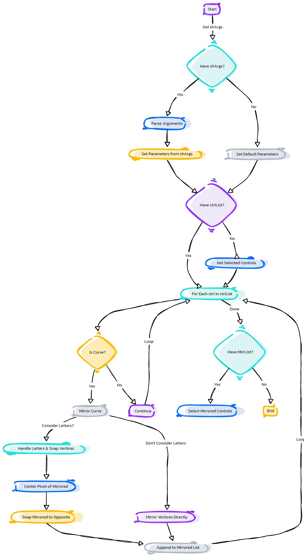
Purpose:
:: Mirrors control shapes in Autodesk Maya from one side to another, with options for control list, source string, replacement string, replacement count, and letter consideration.
- Parameters:
ctrlList – (<type list, optional>) # List of control shapes to mirror. If not provided, function relies on the selection list.
srcStr – (<type str, optional>) # Source string for identifying the side to mirror from.
repStr – (<type str, optional>) # Replacement string for the mirrored side.
repCount – (<type int, optional>) # Number of times to replace the string. Default is 1.
letters – (<type bool, optional>) # Whether to consider letters in the mirroring process. Default is False.
- Returns:
(<type None>) # None. The control shapes are mirrored in the Maya scene.
Code Examples:
>>> ctrl_list = ['LeftArm_Ctrl', 'RightArm_Ctrl']  # Specify a list of control names
>>> source_string = 'L_'  # Specify the source string
>>> replacement_string = 'R_'  # Specify the replacement string
>>> replacement_count = 2  # Specify the replacement count
>>> consider_letters = True  # Specify whether to consider letters in mirroring process
>>> mirrored_controls = mirrorCtrlShapes(ctrl_list, source_string, replacement_string, replacement_count, consider_letters)
graph TB Start[("fa:fa-play Start")] --> CheckShArgs{"/fas:fa-question-circle Check shArgs"} CheckShArgs --"If shArgs Exist"--> ParseShArgs["/fas:fa-cogs Parse shArgs"] CheckShArgs --"If shArgs Does Not Exist"--> InitializeParameters["/fas:fa-wrench Initialize Parameters"] InitializeParameters --> GetSelectedObjects{"/fas:fa-check-square Get Selected Objects"} GetSelectedObjects --"For Each Selected Object"--> CheckCtrlList{"/fas:fa-question-circle Check Control List"} CheckCtrlList --"If Control List Exists"--> IterateCtrlList["/fas:fa-clipboard Iterate Control List"] CheckCtrlList --"If Control List Does Not Exist"--> SelectControls["/fas:fa-mouse-pointer Select Controls"] IterateCtrlList --> CheckControlType{"/fas:fa-question-circle Check Control Type"} CheckControlType --"If Control is Not a Curve"--> ContinueIteration["/fas:fa-arrow-right Continue Iteration"] CheckControlType --"If Control is a Curve"--> MirrorControl["/fas:fa-clone Mirror Control"] ContinueIteration --> IterateCtrlList MirrorControl --"If Letters are Considered"--> SnapVertices["/fas:fa-magnet Snap Vertices"] MirrorControl --"If Letters are Not Considered"--> MirrorVertices["/fas:fa-arrows Mirror Vertices"] SnapVertices --> CenterPivot["/fas:fa-crosshairs Center Pivot"] CenterPivot --> SnapShapeToOpposite["/fas:fa-hand-rock Snap Shape to Opposite"] SnapShapeToOpposite --> AppendToMirrList["/fas:fa-plus Append to Mirrored List"] MirrorVertices --> SelectVertices["/fas:fa-mouse-pointer Select Vertices"] SelectVertices --> CalculateOppositePosition["/fas:fa-calculator Calculate Opposite Position"] CalculateOppositePosition --> SetOppositePosition["/fas:fa-crosshairs Set Opposite Position"] SetOppositePosition --> AppendToMirrList AppendToMirrList --"For Each Control"--> IterateCtrlList IterateCtrlList --"If Control List is Not Empty"--> SelectMirroredControls["/fas:fa-mouse-pointer Select Mirrored Controls"] IterateCtrlList --"If Control List is Empty"--> End["/fas:fa-stop End"] style Start fill:#00cc00,stroke:#000,stroke-width:3px style CheckShArgs fill:#ffcc00,stroke:#000,stroke-width:2px style ParseShArgs fill:#ff9999,stroke:#000,stroke-width:2px style InitializeParameters fill:#99ccff,stroke:#000,stroke-width:2px style GetSelectedObjects fill:#cc99ff,stroke:#000,stroke-width:2px style CheckCtrlList fill:#99ff99,stroke:#000,stroke-width:2px style IterateCtrlList fill:#ffcc99,stroke:#000,stroke-width:2px style CheckControlType fill:#ccffcc,stroke:#000,stroke-width:2px style ContinueIteration fill:#99ccff,stroke:#000,stroke-width:2px style MirrorControl fill:#cc99ff,stroke:#000,stroke-width:2px style SnapVertices fill:#ffcc99,stroke:#000,stroke-width:2px style CenterPivot fill:#ccffcc,stroke:#000,stroke-width:2px style SnapShapeToOpposite fill:#99ff99,stroke:#000,stroke-width:2px style AppendToMirrList fill:#ffcc99,stroke:#000,stroke-width:2px style SelectVertices fill:#ccffcc,stroke:#000,stroke-width:2px style CalculateOppositePosition fill:#99ccff,stroke:#000,stroke-width:2px style SetOppositePosition fill:#cc99ff,stroke:#000,stroke-width:2px style SelectMirroredControls fill:#ffcc99,stroke:#000,stroke-width:2px style End fill:#ff6666,stroke:#000,stroke-width:3px- Flow Chart Description:
This flowchart illustrates the mirrorCtrlShapes function:
Checks if shArgs exist, and if so, parses the ctrlList, srcStr, repStr, repCount, and letters from it.
If shArgs do not exist, initializes parameters with default values.
Retrieves a list of selected controls (control curves).
- For each selected control:
Checks if it’s a curve shape (control shape).
If it’s not a curve shape, continues to the next control.
If it’s a curve shape, proceeds to mirror it.
- If letters are considered in the mirroring process:
Snaps vertices to their opposite positions.
Centers the pivot of the mirrored control.
Snaps the shape to the opposite location.
- If letters are not considered:
Mirrors vertices by changing their X-coordinates to the opposite side.
Appends the mirrored control to the list of mirrored controls.
After processing all controls, selects the mirrored controls if the list is not empty.
- eCtrl.moonCtrl(self, ctrlName=None, grpLevel=1, initRot=[0, 0, 0], ctrlType=1, **shArgs)#
[shArgs : cn=ctrlName, gl=grpLevel, ir=initRot, ct=ctrlType]
Purpose:
:: Facilitates the creation of a moon-shaped control in Autodesk Maya, offering various customization options like control name, group level, initial rotation, and control type.
This function is ideal for rigging scenarios where a unique, moon-shaped control is needed.
The moon shape can provide a distinctive and intuitive control for animators and riggers, especially for celestial or thematic character rigs.
- Parameters:
ctrlName – <str, optional> # Name for the moon control. If not provided, defaults to ‘as_Moon_Ctrl’.
grpLevel – <int, optional> # Specifies the hierarchy level for grouping the control. Default is 1.
initRot – <list of float, optional> # Initial rotation of the control, specified as [x, y, z]. Default is [0, 0, 0].
ctrlType – <int, optional> # Type of moon control to be created. Default is 1.
- Returns:
<list of asNode> # A list with the control and its top group as Maya nodes, based on grpLevel.
Usage Examples:
>>> moon_control = moonCtrl(ctrlName="myMoonCtrl", ctrlType=1)[0]
# Creates a moon control with specific shape and default settings.

>>> moon_control, moon_control_group = moonCtrl(ctrlName="customMoon", ctrlType=2, grpLevel=2)
# Creates a custom moon control with a specific group level and control type.
graph TB Start[("fa:fa-play Start")] --> CheckShArgs{"/fas:fa-question-circle Check shArgs"} CheckShArgs --"If shArgs Exist"--> ParseShArgs["/fas:fa-cogs Parse shArgs"] CheckShArgs --"If shArgs Does Not Exist"--> InitializeParameters["/fas:fa-wrench Initialize Parameters"] InitializeParameters --> CreateMoonControl{"/fas:fa-pen-nib Create Moon Control"} ParseShArgs --"If shArgs Exist"--> CreateMoonControl CreateMoonControl --> RotateMoonControl["/fas:fa-sync Rotate Moon Control"] RotateMoonControl --"Rotate Moon Control"--> FreezeMoonControl["/fas:fa-snowflake Freeze Moon Control"] FreezeMoonControl --"Freeze Moon Control"--> DeleteHistory["/fas:fa-trash-alt Delete History"] DeleteHistory --"Delete History"--> CreateControlGroup{"/fas:fa-object-group Create Control Group"} CreateControlGroup --"Create Control Group"--> ApplyControlColor["/fas:fa-paint-brush Apply Control Color"] ApplyControlColor --"Apply Control Color"--> End["/fas:fa-stop End"] style Start fill:#00cc00,stroke:#000,stroke-width:3px style CheckShArgs fill:#ffcc00,stroke:#000,stroke-width:2px style ParseShArgs fill:#ff9999,stroke:#000,stroke-width:2px style InitializeParameters fill:#99ccff,stroke:#000,stroke-width:2px style CreateMoonControl fill:#ccffcc,stroke:#000,stroke-width:2px style RotateMoonControl fill:#ccffcc,stroke:#000,stroke-width:2px style FreezeMoonControl fill:#99ff99,stroke:#000,stroke-width:2px style DeleteHistory fill:#cc99ff,stroke:#000,stroke-width:2px style CreateControlGroup fill:#99ccff,stroke:#000,stroke-width:2px style ApplyControlColor fill:#ffcc99,stroke:#000,stroke-width:2px style End fill:#ff6666,stroke:#000,stroke-width:3px- Flow Chart Description:
This flowchart illustrates the moonCtrl function:
Checks if shArgs exist and parses them if present.
Initializes parameters for control creation, including ctrlName, grpLevel, initRot, and ctrlType.
Creates a moon-shaped control based on the specified ctrlType.
Rotates the moon control based on the provided initRot values.
Freezes the transformations of the control.
Deletes the history of the control.
Creates a control group based on the grpLevel.
Applies control color to the control.
- eCtrl.multiCurvCtrl(self, curvList=None, ctrlName=None, freezeCurvs=False, **shArgs)#
[**shArgs : cl=curvList, cn=ctrlName, fc=freezeCurvs]
Purpose:
:: Creates a single shape control from multiple curves in Autodesk Maya, with options for curve list, control name, and whether to freeze the curves.
- Parameters:
curvList – (<type list, optional>) # List of curves needed as input to create the single shape control.
ctrlName – (<type str, optional>) # Name for the resulting control.
freezeCurvs – (<type bool, optional>) # Determines if the input curves should be frozen (transform reset). Default is False.
- Returns:
(<type asNode>) # The control curve created from the multiple input curves as a Maya node.
Usage:
To create single shape control from multiple curves

ctrl              =eCtrl.multiCurvCtrl()[0]
ctrlGrp           =eCtrl.multiCurvCtrl()[-1]
ctrl, ctrlGrp =eCtrl.multiCurvCtrl()
Returns:
return ctrlCurv #_ asNode
Fonts:
#_ fontList =['Palatino Linotype', 'Bolide', 'Vectroid', 'Snap ITC', 'Quaint', 'Ravie']
#_ ['Outer Sider BRK', 'ChangChangWoodcut']
#_ textCurves(ch=0, t='ikfk', f= 'Quaint|h-16|w700|c0')
#_ font =fontList[rand.randint(0, 5)]
graph TB Start[("fa:fa-play Start")] --> CheckShArgs{"/fas:fa-question-circle Check shArgs"} CheckShArgs --"If shArgs Exist"--> ParseShArgs["/fas:fa-cogs Parse shArgs"] CheckShArgs --"If shArgs Does Not Exist"--> InitializeParameters["/fas:fa-wrench Initialize Parameters"] InitializeParameters --> GetSelectedObjects{"/fas:fa-check-square Get Selected Objects"} GetSelectedObjects --"For Each Selected Object"--> CheckCtrlList{"/fas:fa-question-circle Check Control List"} CheckCtrlList --"If Control List Exists"--> IterateCtrlList["/fas:fa-clipboard Iterate Control List"] CheckCtrlList --"If Control List Does Not Exist"--> SelectControls["/fas:fa-mouse-pointer Select Controls"] IterateCtrlList --> CheckControlType{"/fas:fa-question-circle Check Control Type"} CheckControlType --"If Control is Not a Curve"--> ContinueIteration["/fas:fa-arrow-right Continue Iteration"] CheckControlType --"If Control is a Curve"--> MirrorControl["/fas:fa-clone Mirror Control"] ContinueIteration --> IterateCtrlList MirrorControl --"If Letters are Considered"--> SnapVertices["/fas:fa-magnet Snap Vertices"] MirrorControl --"If Letters are Not Considered"--> MirrorVertices["/fas:fa-arrows Mirror Vertices"] SnapVertices --> CenterPivot["/fas:fa-crosshairs Center Pivot"] CenterPivot --> SnapShapeToOpposite["/fas:fa-hand-rock Snap Shape to Opposite"] SnapShapeToOpposite --> AppendToMirrList["/fas:fa-plus Append to Mirrored List"] MirrorVertices --> SelectVertices["/fas:fa-mouse-pointer Select Vertices"] SelectVertices --> CalculateOppositePosition["/fas:fa-calculator Calculate Opposite Position"] CalculateOppositePosition --> SetOppositePosition["/fas:fa-crosshairs Set Opposite Position"] SetOppositePosition --> AppendToMirrList AppendToMirrList --"For Each Control"--> IterateCtrlList IterateCtrlList --"If Control List is Not Empty"--> SelectMirroredControls["/fas:fa-mouse-pointer Select Mirrored Controls"] IterateCtrlList --"If Control List is Empty"--> End["/fas:fa-stop End"] style Start fill:#00cc00,stroke:#000,stroke-width:3px style CheckShArgs fill:#ffcc00,stroke:#000,stroke-width:2px style ParseShArgs fill:#ff9999,stroke:#000,stroke-width:2px style InitializeParameters fill:#99ccff,stroke:#000,stroke-width:2px style GetSelectedObjects fill:#cc99ff,stroke:#000,stroke-width:2px style CheckCtrlList fill:#99ff99,stroke:#000,stroke-width:2px style IterateCtrlList fill:#ffcc99,stroke:#000,stroke-width:2px style CheckControlType fill:#ccffcc,stroke:#000,stroke-width:2px style ContinueIteration fill:#99ccff,stroke:#000,stroke-width:2px style MirrorControl fill:#cc99ff,stroke:#000,stroke-width:2px style SnapVertices fill:#ffcc99,stroke:#000,stroke-width:2px style CenterPivot fill:#ccffcc,stroke:#000,stroke-width:2px style SnapShapeToOpposite fill:#99ff99,stroke:#000,stroke-width:2px style AppendToMirrList fill:#ffcc99,stroke:#000,stroke-width:2px style SelectVertices fill:#ccffcc,stroke:#000,stroke-width:2px style CalculateOppositePosition fill:#99ccff,stroke:#000,stroke-width:2px style SetOppositePosition fill:#cc99ff,stroke:#000,stroke-width:2px style SelectMirroredControls fill:#ffcc99,stroke:#000,stroke-width:2px style End fill:#ff6666,stroke:#000,stroke-width:3px- Flow Chart Description:
This flowchart illustrates the mirrorCtrlShapes function:
Checks if shArgs exist, and if so, parses the ctrlList, srcStr, repStr, repCount, and letters from it.
If shArgs do not exist, initializes parameters with default values.
Retrieves a list of selected controls (control curves).
- For each selected control:
Checks if it’s a curve shape (control shape).
If it’s not a curve shape, continues to the next control.
If it’s a curve shape, proceeds to mirror it.
- If letters are considered in the mirroring process:
Snaps vertices to their opposite positions.
Centers the pivot of the mirrored control.
Snaps the shape to the opposite location.
- If letters are not considered:
Mirrors vertices by changing their X-coordinates to the opposite side.
Appends the mirrored control to the list of mirrored controls.
After processing all controls, selects the mirrored controls if the list is not empty.
- eCtrl.nailCtrl(self, ctrlName=None, grpLevel=1, snapPiv=True, initRot=[0, 0, 0], ctrlType=1, **shArgs)#
[shArgs : cn=ctrlName, gl=grpLevel, sp=snapPiv, ir=initRot, ct=ctrlType]
Purpose:
:: Designs a nail-shaped control in Autodesk Maya, ideal for various rigging tasks. The control is customizable in terms of name, group level, pivot snapping, initial rotation, and control type.
The nail shape can be particularly useful for controls requiring a pointed or directed indication, such as directional markers or pinpoints in a rigging setup.
The customization options allow for flexible use across different rigging scenarios and needs.
- Parameters:
ctrlName – <str, optional> # Name for the nail control. Defaults to ‘as_Nail_Ctrl’.
grpLevel – <int, optional> # Determines the grouping hierarchy level for the control. Default is 1.
snapPiv – <bool, optional> # Indicates whether the control’s pivot should be snapped. Default is True.
initRot – <list of float, optional> # Specifies the initial rotation of the control, formatted as [x, y, z]. Default is [0, 0, 0].
ctrlType – <int, optional> # Defines the type of nail control to be generated. Default is 1.
- Returns:
<list of asNode> # A list comprising the control and its top group as Maya nodes, based on the provided group level.
Usage Examples:
>>> nail_control = nailCtrl(ctrlName="myNailCtrl", ctrlType=1)[0]
# Creates a nail control with the default settings.

>>> nail_control, nail_control_group = nailCtrl(ctrlName="customNail", ctrlType=1, grpLevel=2, snapPiv=False)
# Creates a custom nail control with specified group level and pivot snapping settings.
graph TB Start[("fa:fa-play Start")] --> CheckShArgs{"/fas:fa-question-circle Check shArgs"} CheckShArgs --"If shArgs Exist"--> ParseShArgs["/fas:fa-cogs Parse shArgs"] CheckShArgs --"If shArgs Does Not Exist"--> InitializeParameters["/fas:fa-wrench Initialize Parameters"] InitializeParameters --> CreateNailControl{"/fas:fa-pen-nib Create Nail Control"} ParseShArgs --"If shArgs Exist"--> CreateNailControl CreateNailControl --> RotateNailControl["/fas:fa-sync Rotate Nail Control"] RotateNailControl --"Rotate Nail Control"--> FreezeNailControl["/fas:fa-snowflake Freeze Nail Control"] FreezeNailControl --"Freeze Nail Control"--> DeleteHistory["/fas:fa-trash-alt Delete History"] DeleteHistory --"Delete History"--> CreateControlGroup{"/fas:fa-object-group Create Control Group"} CreateControlGroup --"Create Control Group"--> ApplyControlColor["/fas:fa-paint-brush Apply Control Color"] ApplyControlColor --"Apply Control Color"--> End["/fas:fa-stop End"] style Start fill:#00cc00,stroke:#000,stroke-width:3px style CheckShArgs fill:#ffcc00,stroke:#000,stroke-width:2px style ParseShArgs fill:#ff9999,stroke:#000,stroke-width:2px style InitializeParameters fill:#99ccff,stroke:#000,stroke-width:2px style CreateNailControl fill:#ccffcc,stroke:#000,stroke-width:2px style RotateNailControl fill:#ccffcc,stroke:#000,stroke-width:2px style FreezeNailControl fill:#99ff99,stroke:#000,stroke-width:2px style DeleteHistory fill:#cc99ff,stroke:#000,stroke-width:2px style CreateControlGroup fill:#99ccff,stroke:#000,stroke-width:2px style ApplyControlColor fill:#ffcc99,stroke:#000,stroke-width:2px style End fill:#ff6666,stroke:#000,stroke-width:3px- Flow Chart Description:
This flowchart illustrates the nailCtrl function:
Checks if shArgs exist and parses them if present.
Initializes parameters for control creation, including ctrlName, grpLevel, snapPiv, initRot, and ctrlType.
Creates a nail-shaped control based on the specified ctrlType.
Rotates the nail control based on the provided initRot values.
Freezes the transformations of the control.
Deletes the history of the control.
Creates a control group based on the grpLevel and determines pivot snapping.
Applies control color to the control.
- eCtrl.pinCtrl(self, ctrlName=None, grpLevel=3, initRot=[0, 0, 0], ctrlType=1, grpSufxList=None, **shArgs)#
[shArgs : cn=ctrlName, gl=grpLevel, ir=initRot, ct=ctrlType, gsl=grpSufxList]
Purpose:
:: Provides a flexible tool for creating pin-shaped controls in Autodesk Maya, ideal for specific rigging requirements.
The pin control is versatile for rigging scenarios where a pin-like manipulation is required.
Offers customization in terms of control type, initial rotation, and grouping, catering to different rigging needs.
- Parameters:
ctrlName – <str, optional> # Name for the pin control. Defaults to a standard naming convention if not specified.
grpLevel – <int, optional> # Determines the grouping level of the control, affecting its hierarchy. Default is 3.
initRot – <list, optional> # Sets the initial rotation of the control, specified as [x, y, z]. Default is [0, 0, 0].
ctrlType – <int, optional> # Type of pin control, allowing for different shapes and styles. Default is 1.
grpSufxList – <list/str, optional> # Custom suffixes for group names, enhancing organizational flexibility.
- Returns:
<list> # Returns a list containing the pin control and its top group as Maya nodes, structured as per grpLevel.
Code Examples:
>>> pin_control = pinCtrl(ctrlName="myPinCtrl", grpLevel=3, ctrlType=2)
# Creates a pin control with a specific name, group level, and control type.
graph TD Start[("fa:fa-play Start")] --> CheckShArgs{"/fas:fa-question-circle Check shArgs"} CheckShArgs --"If shArgs Exist"--> ParseShArgs["/fas:fa-cogs Parse shArgs"] CheckShArgs --"If shArgs Does Not Exist"--> InitializeParameters["/fas:fa-wrench Initialize Parameters"] InitializeParameters --> GenerateControl["/fas:fa-circle Generate Control"] GenerateControl --> RotateControl["/fas:fa-redo Rotate Control"] RotateControl --> GroupControl["/fas:fa-object-group Group Control"] GroupControl --> ApplyColor["/fas:fa-paint-brush Apply Color"] ApplyColor --> End["/fas:fa-stop End"] style Start fill:#00cc00,stroke:#000,stroke-width:3px style CheckShArgs fill:#ffcc00,stroke:#000,stroke-width:2px style ParseShArgs fill:#ff9999,stroke:#000,stroke-width:2px style InitializeParameters fill:#99ccff,stroke:#000,stroke-width:2px style GenerateControl fill:#99ff99,stroke:#000,stroke-width:2px style RotateControl fill:#99ff99,stroke:#000,stroke-width:2px style GroupControl fill:#99ff99,stroke:#000,stroke-width:2px style ApplyColor fill:#99ff99,stroke:#000,stroke-width:2px style End fill:#ff6666,stroke:#000,stroke-width:3px- Flow Chart Description:
This flowchart illustrates the pinCtrl function:
Checks if shArgs exist, and if so, parses the function arguments from it.
If shArgs do not exist, initializes parameters with default values.
Generates a pin-shaped control in Autodesk Maya based on the specified control type.
Rotates the control based on the initRot parameter.
Groups the control based on the grpLevel and grpSufxList parameters.
Applies color to the control using the applyCtrlColor method.
Ends the process.
- eCtrl.pistolCtrl(self, ctrlName=None, grpLevel=1, ctrlType=1)#
[**shArgs : cn=ctrlName, gl=grpLevel, ct=ctrlType]
Purpose:
:: Creates a pistol-shaped control in Autodesk Maya, customizable with control name, group level, and control type.
This control is designed for scenarios where a pistol-like shape is necessary, such as character rigging or prop animation.
The customization options allow for a wide range of uses and adjustments to fit specific rigging needs.
- Parameters:
ctrlName – <str, optional> #Name for the pistol control.
grpLevel – <int, optional> #Specifies the hierarchy level for grouping the control. Default is 1.
ctrlType – <int, optional> #Type of pistol control to be created. Default is 1.
- Returns:
<list> #A list containing the control and its top group as Maya nodes, based on grpLevel.
graph TB Start[("fa:fa-play Start")] --> CheckCtrlType{"/fas:fa-question-circle Check Control Type"} CheckCtrlType --"Control Type 1"--> CreateCurve1[("/fas:fa-pencil-ruler Create Curve 1")] CheckCtrlType --"Other Control Types"--> CreateCurve2[("/fas:fa-pencil-ruler Create Curve 2")] CreateCurve1 --> CombineCurves[("/fas:fa-object-group Combine Curves")] CreateCurve2 --> CombineCurves CombineCurves --> ApplyCtrlColor[("/fas:fa-paint-brush Apply Control Color")] ApplyCtrlColor --> CreateCtrlGroup[("/fas:fa-layer-group Create Control Group")] CreateCtrlGroup --> End[("fas:fa-stop-circle End")] style Start fill:#00cc00,stroke:#000,stroke-width:3px style CheckCtrlType fill:#ffcc00,stroke:#000,stroke-width:2px style CreateCurve1 fill:#99ff99,stroke:#000,stroke-width:2px style CreateCurve2 fill:#99ff99,stroke:#000,stroke-width:2px style CombineCurves fill:#99ccff,stroke:#000,stroke-width:2px style ApplyCtrlColor fill:#ff9999,stroke:#000,stroke-width:2px style CreateCtrlGroup fill:#cc99ff,stroke:#000,stroke-width:2px style End fill:#ff6666,stroke:#000,stroke-width:3px- Flow Chart Description:
This flowchart illustrates the pistolCtrl function:
The function begins by checking the specified control type.
Based on the control type, it creates one or more curves to form the base of the pistol control.
These curves are then combined to form the final pistol control shape.
The control color is applied to the pistol control for visual identification.
A control group is created at the specified group level to organize the control within the Maya hierarchy.
The process concludes with the creation of the pistol control and its associated group.
- eCtrl.pivotCtrl(self, baseCtrl=None, ctrlName=None, grpLevel=1, ctrlType=1, initRot=[0, 0, 0], snapPiv=1, grpSufxList=None, colorVal=None, attrDivider=1, **shArgs)#
[**shArgs : bc=baseCtrl, cn=ctrlName, gl=grpLevel, ct=ctrlType, ir=initRot, sp=snapPiv, gsl=grpSufxList, cv=colorVal, ad=attrDivider]
Purpose:
:: Generates a pivot control in Autodesk Maya, with options for base control, control name, group level, control type, initial rotation, pivot snapping, group suffix list, color value, and attribute divider.
Ideal for creating a secondary control that can be used to adjust the pivot of another control, enhancing rig flexibility.
The pivot control can be attached to any existing control, allowing for dynamic pivot adjustments during animation.
- Parameters:
baseCtrl – <Maya node, optional> #The base control to which the pivot control is associated.
ctrlName – <str, optional> #Name for the pivot control.
grpLevel – <int, optional> #Hierarchy level for grouping the control. Default is 1.
ctrlType – <int, optional> #Type of pivot control to create. Default is 1.
initRot – <list, optional> #Initial rotation of the control, given as [x, y, z]. Default is [0, 0, 0].
snapPiv – <bool, optional> #Whether to snap the control’s pivot. Default is 1.
grpSufxList – <list/str, optional> #Suffix list for the control’s groups.
colorVal – <color, optional> #Color value to apply to the control.
attrDivider – <int, optional> #Attribute divider for the control. Default is 1.
- Returns:
<list> #A list containing the pivot control and its top group as Maya nodes, based on grpLevel.
graph TB Start[("fa:fa-play Start")] --> CheckBaseCtrl{"/fas:fa-question-circle Check Base Control"} CheckBaseCtrl --"If baseCtrl is specified"--> CreatePivotCtrl[("/fas:fa-pencil-ruler Create Pivot Control")] CheckBaseCtrl --"If baseCtrl is not specified"--> AutoSelectBaseCtrl[("/fas:fa-mouse-pointer Auto Select Base Control")] AutoSelectBaseCtrl --> CreatePivotCtrl CreatePivotCtrl --> CheckCtrlType{"/fas:fa-question-circle Check Control Type"} CheckCtrlType --"Control Type 1"--> CreateCurve1[("/fas:fa-pencil-ruler Create Curve 1")] CheckCtrlType --"Other Control Types"--> CreateCurve2[("/fas:fa-pencil-ruler Create Curve 2")] CreateCurve1 --> CombineCurves[("/fas:fa-object-group Combine Curves")] CreateCurve2 --> CombineCurves CombineCurves --> ScaleAndFreeze[("/fas:fa-search-plus Scale and Freeze Transform")] ScaleAndFreeze --> FinalizeCtrl[("/fas:fa-check-circle Finalize Control")] FinalizeCtrl --> CheckBaseCtrlAttr[("/fas:fa-search-plus Check Base Control Attribute")] CheckBaseCtrlAttr --"Base Control Exists"--> SnapAndParentCtrl[("/fas:fa-link Snap and Parent Control")] SnapAndParentCtrl --> LockAttrs[("/fas:fa-lock Lock Attributes")] LockAttrs --> ConnectAttr[("/fas:fa-link Connect Attributes")] ConnectAttr --> End[("fas:fa-stop-circle End")] CheckBaseCtrlAttr --"Base Control Not Specified"--> End style Start fill:#00cc00,stroke:#000,stroke-width:3px style CheckBaseCtrl fill:#ffcc00,stroke:#000,stroke-width:2px style AutoSelectBaseCtrl fill:#99ccff,stroke:#000,stroke-width:2px style CreatePivotCtrl fill:#ff9999,stroke:#000,stroke-width:2px style CheckCtrlType fill:#ffcc00,stroke:#000,stroke-width:2px style CreateCurve1 fill:#99ff99,stroke:#000,stroke-width:2px style CreateCurve2 fill:#99ff99,stroke:#000,stroke-width:2px style CombineCurves fill:#99ccff,stroke:#000,stroke-width:2px style ScaleAndFreeze fill:#cc99ff,stroke:#000,stroke-width:2px style FinalizeCtrl fill:#99ff99,stroke:#000,stroke-width:2px style CheckBaseCtrlAttr fill:#ffcc00,stroke:#000,stroke-width:2px style SnapAndParentCtrl fill:#99ccff,stroke:#000,stroke-width:2px style LockAttrs fill:#cc99ff,stroke:#000,stroke-width:2px style ConnectAttr fill:#99ff99,stroke:#000,stroke-width:2px style End fill:#ff6666,stroke:#000,stroke-width:3px- Flow Chart Description:
This flowchart illustrates the pivotCtrl function:
The process starts by checking if a base control is specified.
If not specified, it automatically selects the base control.
A pivot control is created, and its type is checked.
Depending on the control type, appropriate curves are created and combined to form the pivot control.
The pivot control is scaled and its transformations are frozen for clean usage.
The control is finalized, and its position and rotation are set.
The function checks if the base control has the necessary attribute for pivot control.
If the base control exists, the pivot control is snapped and parented to it.
Relevant attributes are locked for the pivot control.
The pivot control’s attributes are connected to the base control’s pivot attributes.
The process ends with the creation of the pivot control and its group.
- eCtrl.poleCtrl(self, ctrlName=None, sidePos='L_', grpLevel=3, ctrlType=1, initRot=[0, 0, 0], grpSufxList=None, snapPiv=1, colorVal=None, **shArgs)#
[shArgs : cn=ctrlName, sp=sidePos, gl=grpLevel, ct=ctrlType, ir=initRot, gsl=grpSufxList, sp=snapPiv, cv=colorVal]
Purpose:
:: Creates a pole control in Autodesk Maya, with options for control name, side position, group level, control type, initial rotation, group suffix list, pivot snapping, and color value.
Allows for flexible customization of pole controls within Maya, enhancing rigging and animation workflows.
Supports different types of control creation, along with side-specific adjustments and color coding for easy identification.
- Parameters:
ctrlName – <str, optional> # Name for the pole control.
sidePos – <str, optional> # Side position for the control, typically ‘L_’ for left or ‘R_’ for right. Default is ‘L_’.
grpLevel – <int, optional> # Hierarchy level for grouping the control. Default is 3.
ctrlType – <int, optional> # Type of pole control to be created. Default is 1.
initRot – <list, optional> # Initial rotation of the control, given as [x, y, z]. Default is [0, 0, 0].
grpSufxList – <list/str, optional> # Suffix list for the control’s groups.
snapPiv – <bool, optional> # Whether to snap the control’s pivot. Default is 1.
colorVal – <color, optional> # Color value to apply to the control.
- Returns:
<list> # A list containing the control and its top group as Maya nodes, based on grpLevel.
Code Examples:
>>> control_name = "poleControl"
>>> side_position = "L_"
>>> group_level = 3
>>> control_type = 1
>>> initial_rotation = [0, 90, 0]
>>> group_suffix_list = ["_grp1", "_grp2"]
>>> snap_pivot = True
>>> color_value = (1, 0, 0)
>>> pole_control = poleCtrl(control_name, side_position, group_level, control_type, initial_rotation, group_suffix_list, snap_pivot, color_value)
# Creates a left-sided pole control with specified parameters.
graph TB Start[("fa:fa-play Start")] --> CheckSidePos{{"/fas:fa-check-circle Check Side Position"}} CheckSidePos --"Side Position 'L_' or 'LT_'"--> CreateCtrlTypeL{"/fas:fa-question-circle Determine Ctrl Type 'L_'"} CheckSidePos --"Side Position 'R_' or 'RT_'"--> CreateCtrlTypeR{"/fas:fa-question-circle Determine Ctrl Type 'R_'"} CreateCtrlTypeL --"Ctrl Type 1"--> CreateCtrlL1[("/fas:fa-plus-circle Create Ctrl 'L_' Type 1")] CreateCtrlTypeL --"Ctrl Type 2"--> CreateCtrlL2[("/fas:fa-plus-circle Create Ctrl 'L_' Type 2")] CreateCtrlTypeL --"Ctrl Type 3"--> CreateCtrlL3[("/fas:fa-plus-circle Create Ctrl 'L_' Type 3")] CreateCtrlTypeR --"Ctrl Type 1"--> CreateCtrlR1[("/fas:fa-plus-circle Create Ctrl 'R_' Type 1")] CreateCtrlTypeR --"Ctrl Type 2"--> CreateCtrlR2[("/fas:fa-plus-circle Create Ctrl 'R_' Type 2")] CreateCtrlTypeR --"Ctrl Type 3"--> CreateCtrlR3[("/fas:fa-plus-circle Create Ctrl 'R_' Type 3")] CreateCtrlL1 --> FinalizeCtrlL1[("/fas:fa-cog Finalize Ctrl 'L_' Type 1")] CreateCtrlL2 --> FinalizeCtrlL2[("/fas:fa-cog Finalize Ctrl 'L_' Type 2")] CreateCtrlL3 --> FinalizeCtrlL3[("/fas:fa-cog Finalize Ctrl 'L_' Type 3")] CreateCtrlR1 --> FinalizeCtrlR1[("/fas:fa-cog Finalize Ctrl 'R_' Type 1")] CreateCtrlR2 --> FinalizeCtrlR2[("/fas:fa-cog Finalize Ctrl 'R_' Type 2")] CreateCtrlR3 --> FinalizeCtrlR3[("/fas:fa-cog Finalize Ctrl 'R_' Type 3")] FinalizeCtrlL1 --> End[("fas:fa-stop-circle End")] FinalizeCtrlL2 --> End FinalizeCtrlL3 --> End FinalizeCtrlR1 --> End FinalizeCtrlR2 --> End FinalizeCtrlR3 --> End style Start fill:#00cc00,stroke:#000,stroke-width:3px style CheckSidePos fill:#ffcc00,stroke:#000,stroke-width:2px style CreateCtrlTypeL fill:#ff9999,stroke:#000,stroke-width:2px style CreateCtrlTypeR fill:#99ccff,stroke:#000,stroke-width:2px style CreateCtrlL1 fill:#99ff99,stroke:#000,stroke-width:2px style CreateCtrlL2 fill:#cc99ff,stroke:#000,stroke-width:2px style CreateCtrlL3 fill:#ff6666,stroke:#000,stroke-width:3px style CreateCtrlR1 fill:#99ccff,stroke:#000,stroke-width:2px style CreateCtrlR2 fill:#ff9999,stroke:#000,stroke-width:2px style CreateCtrlR3 fill:#99ff99,stroke:#000,stroke-width:2px style FinalizeCtrlL1 fill:#cc99ff,stroke:#000,stroke-width:2px style FinalizeCtrlL2 fill:#ff6666,stroke:#000,stroke-width:3px style FinalizeCtrlL3 fill:#99ccff,stroke:#000,stroke-width:2px style FinalizeCtrlR1 fill:#ff9999,stroke:#000,stroke-width:2px style FinalizeCtrlR2 fill:#99ff99,stroke:#000,stroke-width:2px style FinalizeCtrlR3 fill:#cc99ff,stroke:#000,stroke-width:2px style End fill:#ff6666,stroke:#000,stroke-width:3px- Flow Chart Description:
This flowchart illustrates the poleCtrl function:
Based on the side position, the function determines the control type.
Depending on the control type (1, 2, or 3), the corresponding pole control is created for either ‘L_’ or ‘R_’.
Each control type goes through a finalization process which includes setting pivot, group level, color, and other properties.
The process concludes after the control is finalized.
- eCtrl.rebuildCurves(self, curvesList=None, multiplyCVs=1, deleteHistory=1, **shArgs)#
[**shArgs : cl=curvesList, mc=multiplyCVs, dh=deleteHistory]
Purpose:
:: Rebuilds a list of curves, modifying their structure based on specified parameters.
This function allows for adjusting the complexity and detail of curves in a Maya scene.
It is particularly useful for refining the shape and smoothness of curve-based controls or paths.
- Parameters:
curvesList – <list, optional> #List of curve names to be rebuilt. If not provided, defaults to the current selection.
multiplyCVs – <int, optional> #Factor by which to multiply the number of control vertices (CVs) in each curve.
deleteHistory – <int, optional> #Flag to determine whether to delete history after rebuilding (1 to delete, 0 to keep).
- Returns:
None #No return value, but modifies the curves in place.
graph TB Start[("fa:fa-play Start")] --> CheckCurvesList{"/fas:fa-question-circle Check Curves List"} CheckCurvesList --"Curves List Provided"--> RebuildCurves[("/fas:fa-bezier-curve Rebuild Curves")] CheckCurvesList --"No Curves List"--> SelectCurves{"/fas:fa-mouse-pointer Select Curves"} SelectCurves --> RebuildCurves RebuildCurves --> CheckDeleteHistory{"/fas:fa-history Check Delete History"} CheckDeleteHistory --"Delete History"--> DeleteHistory[("/fas:fa-trash-alt Delete History")] DeleteHistory --> End[("fas:fa-stop-circle End")] CheckDeleteHistory --"Keep History"--> End style Start fill:#00cc00,stroke:#000,stroke-width:3px style CheckCurvesList fill:#ffcc00,stroke:#000,stroke-width:2px style RebuildCurves fill:#99ff99,stroke:#000,stroke-width:2px style SelectCurves fill:#ff9999,stroke:#000,stroke-width:2px style CheckDeleteHistory fill:#99ccff,stroke:#000,stroke-width:2px style DeleteHistory fill:#ff6666,stroke:#000,stroke-width:3px style End fill:#ff6666,stroke:#000,stroke-width:3px- Flow Chart Description:
This flowchart illustrates the rebuildCurves function:
The function begins by checking if a list of curves is provided. If not, it prompts the user to select curves in the scene.
Once the curves list is established, the function rebuilds each curve based on the specified parameters, including the factor by which to multiply the number of control vertices (CVs).
After rebuilding the curves, it checks if the history should be deleted. If yes, the history of the curves is deleted to maintain scene cleanliness.
The process concludes either after deleting the history or directly if the history is to be retained, based on the user’s choice.
- eCtrl.rootCtrl(self, ctrlName=None, grpLevel=3, ctrlType=3, initRot=[0, 0, 0], snapPiv=1, grpSufxList=None, colorVal=None, **shArgs)#
[**shArgs : cn=ctrlName, gl=grpLevel, ct=ctrlType, ir=initRot, sp=snapPiv, gsl=grpSufxList, cv=colorVal]
Purpose:
:: Creates a root control in Autodesk Maya, offering customizable options for control name, group level, control type, initial rotation, pivot snapping, group suffix list, and color value.
This function allows for the dynamic creation of root controls in a 3D scene, aiding in rigging and animation processes.
The control’s appearance and behavior can be extensively customized through various parameters.
- Parameters:
ctrlName – <str, optional> # Name for the root control.
grpLevel – <int, optional> # Hierarchy level for grouping the control. Default is 3.
ctrlType – <int, optional> # Type of root control to be created. Options include different shapes. Default is 3.
initRot – <list, optional> # Initial rotation of the control, given as [x, y, z]. Default is [0, 0, 0].
snapPiv – <bool, optional> # Whether to snap the control’s pivot. Default is 1.
grpSufxList – <list/str, optional> # Suffix list for the control’s groups.
colorVal – <color, optional> # Color value to apply to the control.
- Returns:
<list> # A list containing the control and its top group as Maya nodes, based on grpLevel.
Usage Examples:
>>> ctrlName = "myRootCtrl"
>>> grpLevel = 3
>>> ctrlType = 1
>>> initRot = [45, 0, 0]
>>> snapPiv = True
>>> grpSufxList = ["grp1", "grp2"]
>>> colorVal = (1, 0, 0)
>>> ctrl, ctrlGrp = rootCtrl(ctrlName, grpLevel, ctrlType, initRot, snapPiv, grpSufxList, colorVal)
graph TB Start[("fa:fa-play Start")] --> CheckInputs{"/fas:fa-question-circle Check Inputs"} CheckInputs --"Input Provided"--> CreateControl[("/fas:fa-vector-square Create Root Control")] CreateControl --> GroupControl[("/fas:fa-object-group Group Control")] GroupControl --> ApplyColor[("/fas:fa-palette Apply Color")] ApplyColor --> End[("fas:fa-stop-circle End")] CheckInputs --"No Input"--> Error[("fa:fa-times Error")] style Start fill:#00cc00,stroke:#000,stroke-width:3px style CheckInputs fill:#ffcc00,stroke:#000,stroke-width:2px style CreateControl fill:#99ff99,stroke:#000,stroke-width:2px style GroupControl fill:#ff9999,stroke:#000,stroke-width:2px style ApplyColor fill:#99ccff,stroke:#000,stroke-width:2px style Error fill:#ff6666,stroke:#000,stroke-width:3px style End fill:#ff6666,stroke:#000,stroke-width:3px- Flow Chart Description:
This flowchart illustrates the rootCtrl function:
The function starts by checking if all necessary inputs like control name, group level, control type, initial rotation, pivot snapping, group suffix list, and color value are provided.
If inputs are provided, it creates a root control with the specified parameters.
The control is then grouped according to the hierarchy level specified.
Color is applied to the control for visual differentiation.
The function ends after successfully creating and configuring the root control.
If any inputs are missing, an error is indicated.
- eCtrl.scaleShape(self, nodesList=None, scale=1.1, **shArgs)#
[shArgs: nl=nodesList, s=scale]
Purpose:
:: Provides functionality to uniformly scale the shapes of specified nodes in Autodesk Maya.
Useful in rigging to adjust control shapes for better visibility and interaction.
Offers flexibility to scale multiple shapes at once, enhancing efficiency in rig setup.
- Parameters:
nodesList – <list, optional> # List of nodes whose shapes are to be scaled. Defaults to the current selection if not provided.
scale – <float> # Scaling factor to be applied to the shapes.
- Returns:
None # Scales the specified nodes’ shapes in place without returning any value.
Code Examples:
>>> nodes_to_scale = ["ctrl1", "ctrl2"]
>>> scale_factor = 1.5
>>> scaleShape(nodes_to_scale, scale_factor)
# Scales the shapes of 'ctrl1' and 'ctrl2' by a factor of 1.5.

>>> scaleShape(scale=2.0)
# Scales the shapes of currently selected nodes by a factor of 2.0.
graph TB Start[("fa:fa-play Start")] --> CheckShArgs{{"/fas:fa-question Check shArgs"}} CheckShArgs --"shArgs provided"--> UpdateArgs[("/fas:fa-sync-alt Update Arguments")] CheckShArgs --"shArgs not provided"--> CheckNodesList{{"/fas:fa-list-ol Check Nodes List"}} UpdateArgs --> CheckNodesList CheckNodesList --"Nodes list provided"--> CheckNodeType[("/fas:fa-sitemap Check Node Type")] CheckNodesList --"No nodes list provided"--> SelectNodes[("/fas:fa-mouse-pointer Select Current Nodes")] CheckNodeType --"If node type is Transform"--> GetShapes[("/fas:fa-project-diagram Get Shapes")] GetShapes --> ScaleShapes[("/fas:fa-search-plus Scale Shapes")] CheckNodeType --"If node type is not Transform"--> CheckNodeElement[("/fas:fa-code-branch Check Node Element")] SelectNodes --> ScaleShapes CheckNodeElement --"If element in node"--> ScaleElement[("/fas:fa-expand-arrows-alt Scale Element")] CheckNodeElement --"No element in node"--> CollectCVs[("/fas:fa-vector-square Collect CVs")] CollectCVs --> ScaleShapes ScaleElement --> End[("fas:fa-stop-circle End")] ScaleShapes --> End style Start fill:#00cc00,stroke:#000,stroke-width:3px style CheckShArgs fill:#ffcc00,stroke:#000,stroke-width:2px style UpdateArgs fill:#ff9999,stroke:#000,stroke-width:2px style CheckNodesList fill:#99ccff,stroke:#000,stroke-width:2px style CheckNodeType fill:#ffcc66,stroke:#000,stroke-width:2px style SelectNodes fill:#cc99ff,stroke:#000,stroke-width:2px style GetShapes fill:#99ff99,stroke:#000,stroke-width:2px style ScaleShapes fill:#66ccff,stroke:#000,stroke-width:2px style CheckNodeElement fill:#f0ad4e,stroke:#000,stroke-width:2px style ScaleElement fill:#d9534f,stroke:#000,stroke-width:2px style CollectCVs fill:#5bc0de,stroke:#000,stroke-width:2px style End fill:#ff6666,stroke:#000,stroke-width:3px- Flow Chart Description:
This flowchart illustrates the scaleShape function:
The process starts by checking if shArgs are provided. If so, it updates the arguments for nodes list and scale.
If nodesList is not provided, the function selects the current nodes.
The function then checks if the node type is Transform. If yes, it retrieves the shapes of the nodes.
It scales the shapes based on the provided scale factor.
If the node contains an element, it scales the specific element.
Otherwise, it collects the control vertices (CVs) and scales them.
The function concludes without returning any value, having scaled the specified nodes’ shapes.
- eCtrl.setPoseCtrl(self, ctrlName, grpLevel=1, snapPiv=1, **shArgs)#
[shArgs : cn=ctrlName, gl=grpLevel, sp=snapPiv]
Purpose:
:: Creates a set pose control in Autodesk Maya, providing functionality for control naming, grouping, and pivot snapping.
Useful for rigging and animation workflows where precise control over set poses is required.
Allows for creating neatly organized and easily manageable set pose controls in complex rigs.
- param ctrlName:
<str, required> # Name for the set pose control. This is a required argument.
- param grpLevel:
<int, optional> # Level of grouping for the control, providing organizational structure. Default is 1.
- param snapPiv:
<bool, optional> # Determines if the control’s pivot should be snapped. Default is True (1).
- return:
<list> # A list containing the control and its top group as Maya nodes, based on grpLevel.
Code Examples:
>>> control_name = "mySetPoseControl"
>>> control, control_group = setPoseCtrl(ctrlName=control_name, grpLevel=2)
# Creates a set pose control with the specified name and 2 group levels.
graph TB Start[("fa:fa-play Start")] --> CheckCtrlName{{"/fas:fa-keyboard Check Control Name"}} CheckCtrlName --"CtrlName provided"--> CreateCtrlShape[("/fas:fa-pencil-square-o Create Control Shape")] CheckCtrlName --"CtrlName not provided"--> End[("fas:fa-stop-circle End")] CreateCtrlShape --> GroupControl[("/fas:fa-object-group Group Control")] GroupControl --> ApplyColor[("/fas:fa-paint-brush Apply Color")] ApplyColor --> End style Start fill:#00cc00,stroke:#000,stroke-width:3px style CheckCtrlName fill:#ffcc00,stroke:#000,stroke-width:2px style CreateCtrlShape fill:#99ccff,stroke:#000,stroke-width:2px style GroupControl fill:#cc99ff,stroke:#000,stroke-width:2px style ApplyColor fill:#99ff99,stroke:#000,stroke-width:2px style End fill:#ff6666,stroke:#000,stroke-width:3px- Flow Chart Description:
This flowchart illustrates the setPoseCtrl function:
The process begins by checking if a control name is provided. If not, the function ends immediately.
If a control name is provided, the function proceeds to create the control shape using the ‘curve’ command.
The control is then grouped based on the specified group level and whether the pivot should be snapped.
Finally, a color is applied to the control for easy identification, completing the process.
The function returns a list containing the control and its top group as Maya nodes.
- eCtrl.setSafeZone(lenNode, ratio, ctrlList, **shArgs)#
[shArgs: ln=lenNode, r=ratio, cl=ctrlList]
Purpose:
:: Implements dynamic visual feedback on control nodes based on the length of a specified node and a defined ratio.
Enhances the rigging process by offering a visual safe zone indication for animators.
Dynamically adjusts control node colors to signal when movements are within or exceed safe operational ranges.
- Parameters:
lenNode – <str> #Node that defines the length for the safe zone calculation.
ratio – <float> #Ratio used to determine the boundaries of the safe zone.
ctrlList – <list> #List of control nodes to be visually adjusted in response to the safe zone.
- Returns:
None. Configures an expression to dynamically update control colors based on the safe zone.
Code Examples:
>>> setSafeZone(lenNode="spineLengthNode", ratio=0.2, ctrlList=["ctrl1", "ctrl2", "ctrl3"])
# Sets a safe zone for the 'spineLengthNode' with a 20% ratio, affecting the colors of 'ctrl1', 'ctrl2', 'ctrl3'.
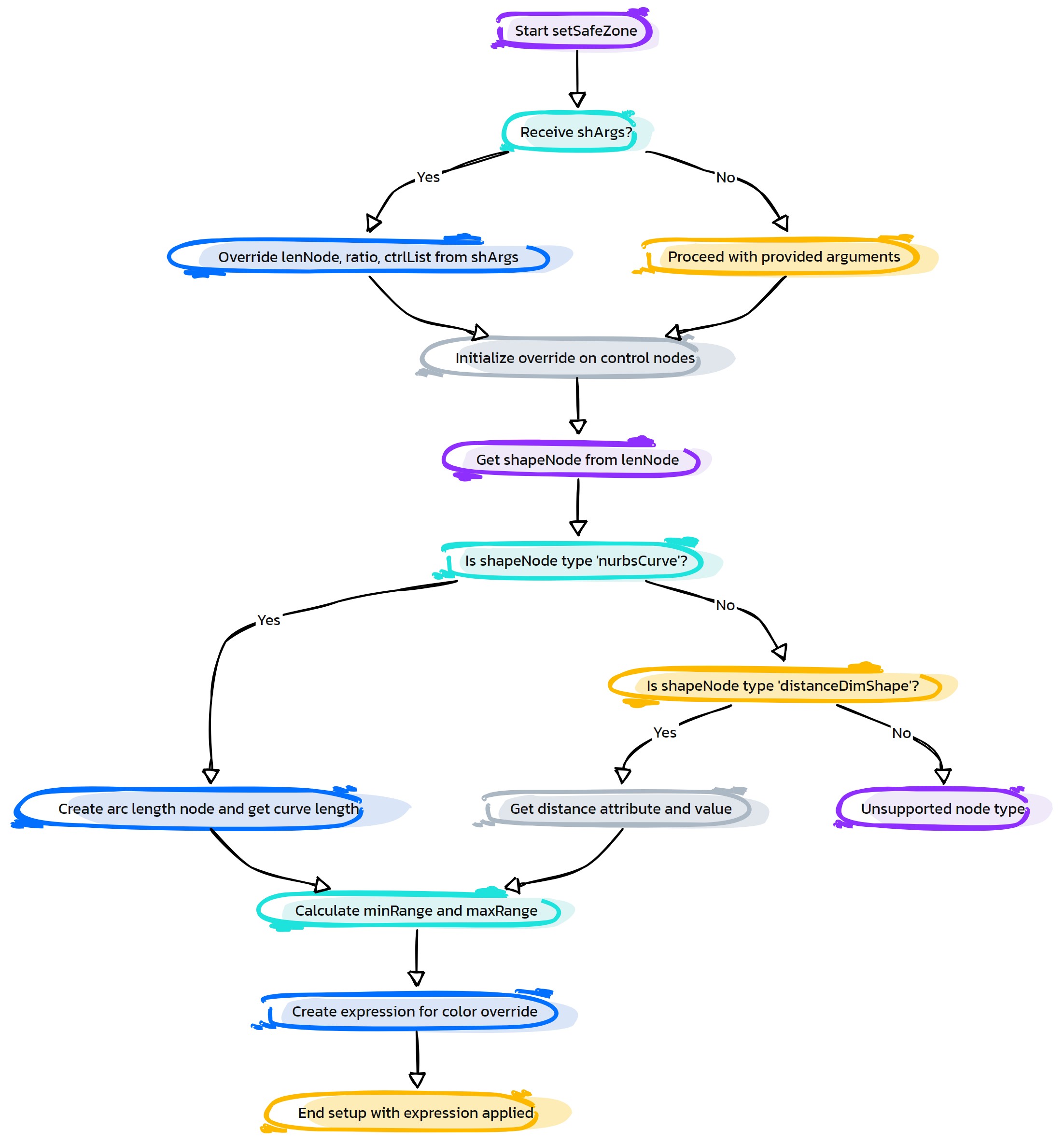
- eCtrl.setScale(self, ctrlList=None, refObj=None, refAttr=None, ratio=1.0, refVal=None, freezeIt=True, useShape=False, **shArgs)#
[**shArgs : cl=ctrlList, ro=refObj, ra=refAttr, r=ratio, rv=refVal, fi=freezeIt, us=useShape]
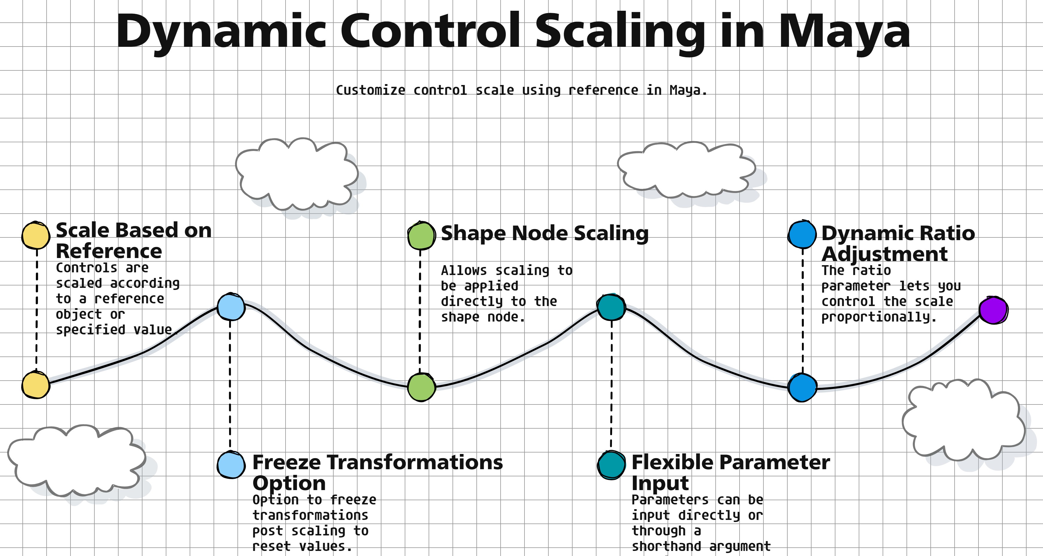
Purpose:
:: Adjusts the scale of a list of controls in Autodesk Maya based on a reference object or value.
Useful for dynamically scaling controls in relation to another object’s attributes or a specified value.
Offers options to freeze transformations and use shape nodes for scaling.
- Parameters:
ctrlList – <list, optional> # List of control names to be scaled. If None, uses the currently selected controls.
refObj – <str, optional> # Name of the reference object for scaling.
refAttr – <str, optional> # Name of the attribute on the reference object to use for scaling.
ratio – <float> # Ratio to apply to the reference attribute value for scaling.
refVal – <float, optional> # Direct reference value to use for scaling if no reference object is specified.
freezeIt – <bool> # Whether to freeze transformations after scaling.
useShape – <bool> # Whether to apply scaling to the shape node instead of the transform node.
- Returns:
None # Does not return a value but scales the specified controls.
Code Examples:
>>> control_list = ["ctrl1", "ctrl2"]
>>> reference_object = "locator1"
>>> scale_ratio = 1.5
>>> setScale(control_list, reference_object, ratio=scale_ratio)
# Scales the controls in control_list based on the scale of reference_object with a ratio of 1.5.
graph TB Start[("fa:fa-play Start")] --> CheckInputs{"/fas:fa-question-circle Check Inputs"} CheckInputs --"If ctrlList is provided"--> DetermineScaling[("/fas:fa-search Determine Scaling")] CheckInputs --"If ctrlList is not provided"--> SelectControls{"/fas:fa-mouse-pointer Select Controls"} SelectControls --"Controls selected"--> DetermineScaling SelectControls --"No controls selected"--> ErrorNoControls[("fa:fa-times-circle Error: No Controls")] DetermineScaling --"Calculate scaling value based on provided parameters"--> ApplyScaling[("/fas:fa-expand-arrows-alt Apply Scaling")] ApplyScaling --> End[("fas:fa-stop-circle End")] ErrorNoControls --> End style Start fill:#00cc00,stroke:#000,stroke-width:3px style CheckInputs fill:#ffcc00,stroke:#000,stroke-width:2px style SelectControls fill:#ff9999,stroke:#000,stroke-width:2px style DetermineScaling fill:#99ccff,stroke:#000,stroke-width:2px style ApplyScaling fill:#99ff99,stroke:#000,stroke-width:2px style ErrorNoControls fill:#ff6666,stroke:#000,stroke-width:3px style End fill:#ff6666,stroke:#000,stroke-width:3px- Flow Chart Description:
This flowchart illustrates the setScale function:
Starts by checking if a list of controls (ctrlList) is provided.
If ctrlList is provided, the function proceeds to determine the scaling value based on the provided parameters (refObj, refAttr, ratio, refVal).
If ctrlList is not provided, it prompts the user to select controls.
After determining the scaling value, the function applies the scaling to the selected controls.
The function concludes after applying the scaling or encountering an error due to no controls being selected.
- eCtrl.setShape(self, curv, crvShapeList, **shArgs)#
[shArgs: c=curv, csl=crvShapeList]
Purpose:
:: Creates a new shape on the specified curve transform, using properties defined in the crvShapeList.
Facilitates the modification of curve shapes in Maya.
Useful for riggers and animators to customize curve controls in a scene.
- Parameters:
curv – <str> # The name of the curve transform to which the new shapes will be added.
crvShapeList – <list> # A list of dictionaries, each specifying properties for a new curve shape.
- Returns:
None # Modifies the curve by adding new shapes based on the provided properties.
Code Examples:
>>> curve_name = "myCurve"
>>> shape_list = [{"points": [(0,0,1), (1,0,0)], "knots": [0,1], "form": 0, "degree": 1}]
>>> setShape(curve_name, shape_list)
# Adds new shapes to the specified curve based on the properties in shape_list.
graph TB Start[("fa:fa-play Start")] --> CheckCurveName{"/fas:fa-question-circle Check Curve Name"} CheckCurveName --"Curve Name Provided"--> GetOldShape[("/fas:fa-cogs Get Old Shape")] GetOldShape --> DeleteOldShape[("/fas:fa-trash Delete Old Shape")] DeleteOldShape --> IterateCrvShapeList{"/fas:fa-repeat Iterate CrvShapeList"} IterateCrvShapeList --"For Each Shape in List"--> CreateNewShape[("/fas:fa-plus-square Create New Shape")] CreateNewShape --> SetShapeAttributes[("/fas:fa-paint-brush Set Shape Attributes")] SetShapeAttributes --> End[("fas:fa-stop-circle End")] CheckCurveName --"No Curve Name Provided"--> Error[("fa:fa-times Error")] style Start fill:#00cc00,stroke:#000,stroke-width:3px style CheckCurveName fill:#ffcc00,stroke:#000,stroke-width:2px style GetOldShape fill:#99ff99,stroke:#000,stroke-width:2px style DeleteOldShape fill:#ff9999,stroke:#000,stroke-width:2px style IterateCrvShapeList fill:#ffcc00,stroke:#000,stroke-width:2px style CreateNewShape fill:#99ccff,stroke:#000,stroke-width:2px style SetShapeAttributes fill:#cc99ff,stroke:#000,stroke-width:2px style Error fill:#ff6666,stroke:#000,stroke-width:3px style End fill:#ff6666,stroke:#000,stroke-width:3px- Flow Chart Description:
This flowchart illustrates the setShape function:
The function begins by checking if a curve name is provided.
If a curve name is provided, it retrieves the old shape of the curve.
The old shape is then deleted to make way for new shapes.
The function iterates through each dictionary in the crvShapeList.
For each dictionary, it creates a new shape on the curve with the specified properties.
The attributes of the new shapes are set, including color, if specified.
The function concludes after creating and setting attributes for all new shapes.
If no curve name is provided, an error is indicated.
- eCtrl.shapeCtrl(self, shapeObj=None, trgt=None, shapeAdd=1, reName=0, deleteShape=1, ctrlName=None, **shArgs)#
[shArgs: so=shapeObj, t=trgt, sa=shapeAdd, rn=reName, ds=deleteShape, cn=ctrlName]
Purpose:
:: Facilitates the creation or modification of control shapes in Autodesk Maya, utilizing a source shape and various customization options.
Streamlines the process of control creation in rigging, allowing for the reuse of existing shapes.
Provides flexibility in shaping controls, catering to specific rigging requirements.
- Parameters:
shapeObj – <Maya node, optional> # The source object from which the shape is derived.
trgt – <Maya node, optional> # The target object to which the shape will be added or modified.
shapeAdd – <bool, optional> # Determines if the shape should be added to the target object. Default is True.
reName – <bool, optional> # Flag to rename the control after shape modification. Default is False.
deleteShape – <bool, optional> # Specifies whether to delete the original shape after modification. Default is True.
ctrlName – <str, optional> # Name for the control to be created or modified.
- Returns:
None # The shape of the target control is modified or created based on the specified options.
Code Examples:
>>> source_shape = "curveShape1"
>>> target_object = "ctrl1"
>>> shapeCtrl(shapeObj=source_shape, trgt=target_object, shapeAdd=True, reName=True, deleteShape=False, ctrlName="newCtrl")
# Modifies the shape of 'ctrl1' using 'curveShape1', renames it to 'newCtrl', without deleting the original shape.

>>> shapeCtrl(shapeObj="shape2", trgt="joint1")
# Adds the shape from 'shape2' to 'joint1', keeping the default options.
graph TB Start[("fa:fa-play Start")] --> CheckShArgs{{"/fas:fa-question Check shArgs"}} CheckShArgs --"shArgs provided"--> UpdateArgs[("/fas:fa-sync-alt Update Arguments")] CheckShArgs --"shArgs not provided"--> CheckShapeAndTarget{{"/fas:fa-question-circle Check Shape and Target"}} UpdateArgs --> CheckShapeAndTarget CheckShapeAndTarget --"Both shapeObj and trgt provided"--> CheckCtrlName[("/fas:fa-i-cursor Check Control Name")] CheckShapeAndTarget --"Either not provided"--> SelectShapeAndTarget[("/fas:fa-mouse-pointer Select Shape and Target")] CheckCtrlName --> GetShapeNodes[("/fas:fa-project-diagram Get Shape Nodes")] SelectShapeAndTarget --> GetShapeNodes GetShapeNodes --> ApplyColorToShapeObj[("/fas:fa-paint-brush Apply Color to Shape Object")] ApplyColorToShapeObj --> CheckTargetShapes{{"/fas:fa-shapes Check Target Shapes"}} CheckTargetShapes --"If target has shapes"--> MakeIdentity[("/fas:fa-vector-square Make Identity on ShapeObj")] CheckTargetShapes --"No shapes in target"--> ParentShape[("/fas:fa-link Parent Shape to Target")] MakeIdentity --> ParentShape ParentShape --> CheckDeleteShape{{"/fas:fa-trash-alt Check Delete Shape"}} CheckDeleteShape --"deleteShape is True"--> DeleteOriginalShapes[("/fas:fa-trash Delete Original Shapes")] CheckDeleteShape --"deleteShape is False"--> SetShapeVisibility[("/fas:fa-eye Set Shape Visibility")] DeleteOriginalShapes --> RenameControl[("/fas:fa-text-width Rename Control")] SetShapeVisibility --> RenameControl RenameControl --> End[("fas:fa-stop-circle End")] style Start fill:#00cc00,stroke:#000,stroke-width:3px style CheckShArgs fill:#ffcc00,stroke:#000,stroke-width:2px style UpdateArgs fill:#ff9999,stroke:#000,stroke-width:2px style CheckShapeAndTarget fill:#99ccff,stroke:#000,stroke-width:2px style SelectShapeAndTarget fill:#cc99ff,stroke:#000,stroke-width:2px style CheckCtrlName fill:#ffcc66,stroke:#000,stroke-width:2px style GetShapeNodes fill:#99ff99,stroke:#000,stroke-width:2px style ApplyColorToShapeObj fill:#66ccff,stroke:#000,stroke-width:2px style CheckTargetShapes fill:#f0ad4e,stroke:#000,stroke-width:2px style MakeIdentity fill:#d9534f,stroke:#000,stroke-width:2px style ParentShape fill:#5bc0de,stroke:#000,stroke-width:2px style CheckDeleteShape fill:#f0ad4e,stroke:#000,stroke-width:2px style DeleteOriginalShapes fill:#d9534f,stroke:#000,stroke-width:2px style SetShapeVisibility fill:#5bc0de,stroke:#000,stroke-width:2px style RenameControl fill:#5cb85c,stroke:#000,stroke-width:2px style End fill:#ff6666,stroke:#000,stroke-width:3px- Flow Chart Description:
This flowchart illustrates the shapeCtrl function:
The process begins by checking if shArgs are provided. If so, it updates the arguments.
If shapeObj and trgt are not provided, the function selects them manually.
It then checks if a control name is provided, if not, the default name of the shape object is used.
The function retrieves the shape nodes from the shape object and applies color to them.
It checks if the target has existing shapes and makes identity on the shape object if required.
The shape nodes are parented to the target object.
Based on the deleteShape flag, it either deletes the original shapes or sets their visibility.
If reName is True, the target control is renamed.
The function ends after modifying the shape of the target control.
- eCtrl.shiftCtrl(self, ctrlList, shiftType='trans', valList=[0, 0, 0], **shArgs)#
[shArgs: cl=ctrlList, st=shiftType, vl=valList]
Purpose:
:: Provides a versatile tool for adjusting the position, rotation, or scale of control curves in a rigging setup.
Enhances rigging efficiency by allowing batch adjustments to multiple controls.
Supports diverse rigging requirements with flexible transformation options.
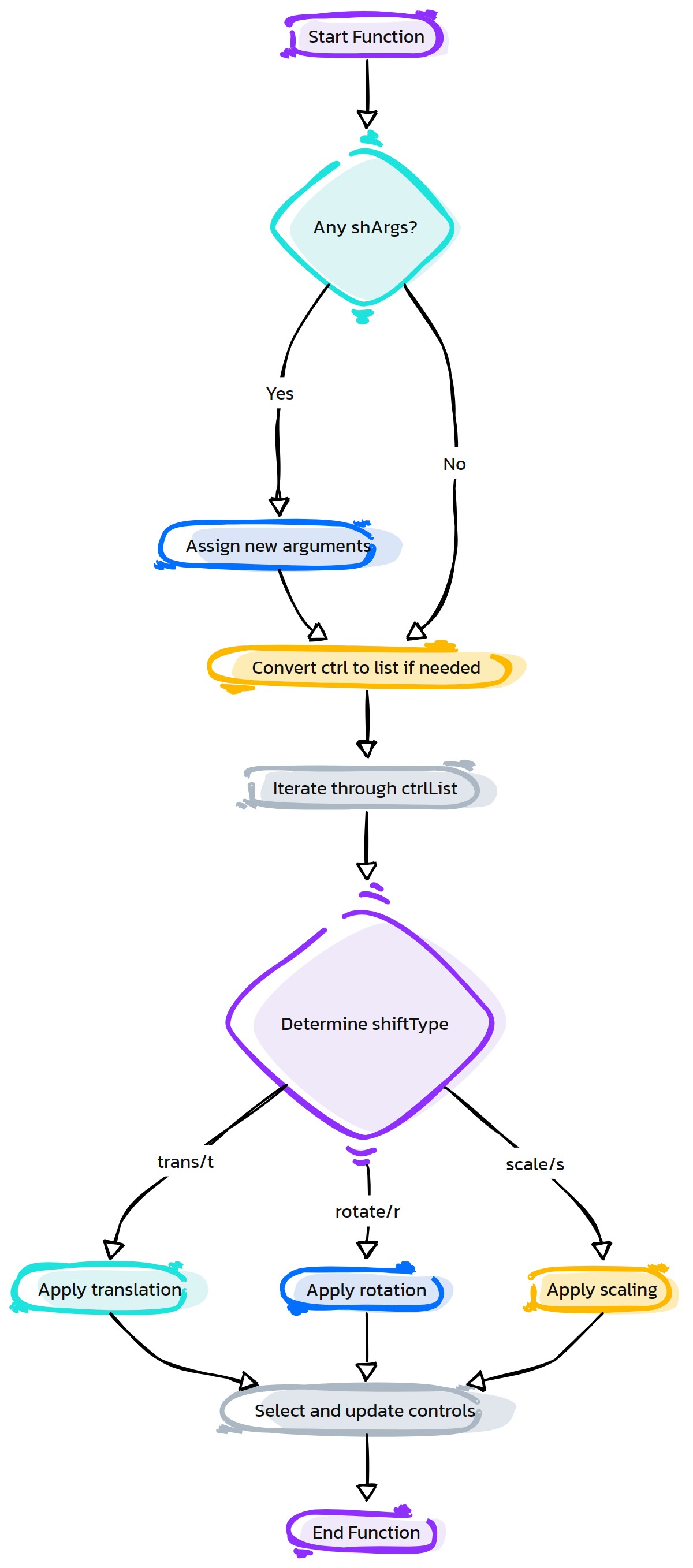
- Parameters:
ctrlList – <list> #List of control curves to be adjusted.
shiftType – <str, optional> #Type of shift to be applied. Options are ‘trans’, ‘rotate’, or ‘scale’. Default is ‘trans’.
valList – <list, optional> #Values for the shift operation, applicable to the shiftType. Defaults to [0, 0, 0].
- Returns:
None #Modifies the control curves as per the specified parameters.
Code Examples:
>>> controls = ["ctrl1", "ctrl2", "ctrl3"]
>>> shiftCtrl(ctrlList=controls, shiftType='trans', valList=[1, 0, 0])
# Moves 'ctrl1', 'ctrl2', 'ctrl3' by 1 unit along the X-axis.

>>> shiftCtrl(ctrlList=["ctrl4"], shiftType='scale', valList=[1.5, 1.5, 1.5])
# Scales 'ctrl4' by 1.5 times in all directions.
graph TB Start[("fa:fa-play Start")] --> CheckShArgs{{"/fas:fa-question Check shArgs"}} CheckShArgs --"shArgs provided"--> UpdateArgs[("/fas:fa-sync-alt Update Arguments")] CheckShArgs --"shArgs not provided"--> VerifyCtrlList[("/fas:fa-check-circle Verify Ctrl List")] UpdateArgs --> VerifyCtrlList VerifyCtrlList --> IterateCtrlList[("/fas:fa-repeat Iterate Ctrl List")] IterateCtrlList --> CheckCtrlShapes{{"/fas:fa-shapes Check Ctrl Shapes"}} CheckCtrlShapes --"Shapes exist"--> GetObjectType[("/fas:fa-info-circle Get Object Type")] CheckCtrlShapes --"No shapes"--> RaiseError[("fas:fa-exclamation-triangle Raise Error")] GetObjectType --> CheckObjectType{{"/fas:fa-cubes Check Object Type"}} CheckObjectType --"Type is nurbsCurve"--> SelectCurveCVs[("/fas:fa-mouse-pointer Select Curve CVs")] CheckObjectType --"Type is not nurbsCurve"--> RaiseError SelectCurveCVs --> ApplyShiftType{{"/fas:fa-arrows-alt Apply Shift Type"}} ApplyShiftType --"trans or t"--> MoveCtrl[("/fas:fa-arrows-alt Move Control")] ApplyShiftType --"rotate or r"--> RotateCtrl[("/fas:fa-undo-alt Rotate Control")] ApplyShiftType --"scale or s"--> ScaleCtrl[("/fas:fa-expand-arrows-alt Scale Control")] MoveCtrl --> SelectCtrls[("/fas:fa-mouse-pointer Select Controls")] RotateCtrl --> SelectCtrls ScaleCtrl --> SelectCtrls SelectCtrls --> BuildTranslateMM[("/fas:fa-cog Build TranslateMM")] BuildTranslateMM --> End[("fas:fa-stop-circle End")] style Start fill:#00cc00,stroke:#000,stroke-width:3px style CheckShArgs fill:#ffcc00,stroke:#000,stroke-width:2px style UpdateArgs fill:#ff9999,stroke:#000,stroke-width:2px style VerifyCtrlList fill:#99ccff,stroke:#000,stroke-width:2px style IterateCtrlList fill:#cc99ff,stroke:#000,stroke-width:2px style CheckCtrlShapes fill:#ffcc66,stroke:#000,stroke-width:2px style GetObjectType fill:#99ff99,stroke:#000,stroke-width:2px style CheckObjectType fill:#66ccff,stroke:#000,stroke-width:2px style SelectCurveCVs fill:#f0ad4e,stroke:#000,stroke-width:2px style ApplyShiftType fill:#d9534f,stroke:#000,stroke-width:2px style MoveCtrl fill:#5bc0de,stroke:#000,stroke-width:2px style RotateCtrl fill:#f0ad4e,stroke:#000,stroke-width:2px style ScaleCtrl fill:#d9534f,stroke:#000,stroke-width:2px style SelectCtrls fill:#5bc0de,stroke:#000,stroke-width:2px style BuildTranslateMM fill:#5cb85c,stroke:#000,stroke-width:2px style RaiseError fill:#d9534f,stroke:#000,stroke-width:2px style End fill:#ff6666,stroke:#000,stroke-width:3px- Flow Chart Description:
This flowchart illustrates the shiftCtrl function:
The process begins with checking if shArgs are provided and updates the arguments accordingly.
It verifies the control list and iterates through each control in the list.
The function checks if the control has shapes and determines the object type.
If the type is not ‘nurbsCurve’, an error is raised.
Curve CVs are selected, and the shift type is applied based on the specified parameters (translation, rotation, or scaling).
After modifying the controls, they are selected and the TranslateMM tool is built.
The process concludes after performing the shift operations on the controls.
- eCtrl.snapCurves2Curv(self, srcCurves, destCurv, **shArgs)#
[shArgs: sc=srcCurves, dc=destCurv]
Purpose:
:: Snaps the vertices of source curves to the corresponding vertices of a destination curve in Autodesk Maya.
Useful for aligning multiple curves to a single reference curve, ensuring consistent vertex positions across them.
Ideal for rigging and animation tasks where precise curve alignment is required.
- Parameters:
srcCurves – <list/str> # Source curves to be snapped. Can be a single curve or a list of curves.
destCurv – <str> # The destination curve to which the source curves’ vertices will be snapped.
- Returns:
None # Modifies the source curves by snapping their vertices to the destination curve without returning any value.
Code Examples:
>>> source_curves = ["curve1", "curve2"]
>>> destination_curve = "mainCurve"
>>> snapCurves2Curv(source_curves, destination_curve)
# Snaps the vertices of 'curve1' and 'curve2' to the corresponding vertices of 'mainCurve'.
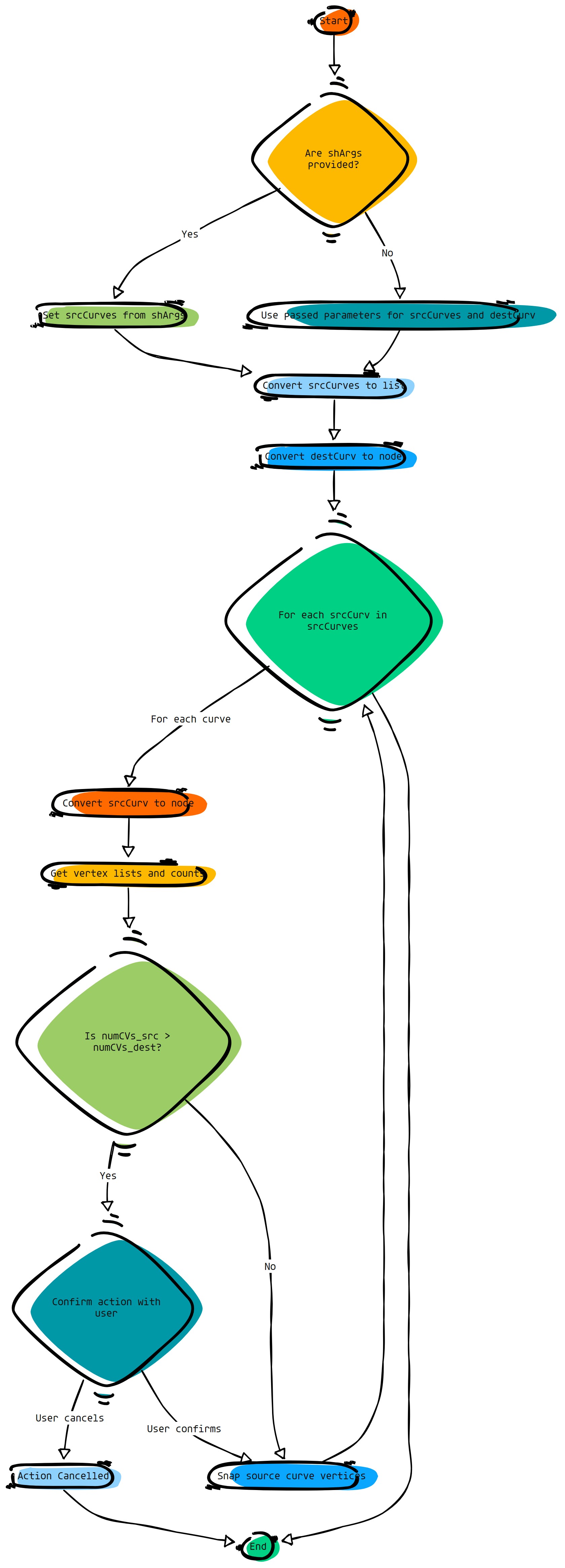
- eCtrl.snapShpTo(self, srcCtrl, destPosOrObj=[0, 0, 0], shapePos=False, **shArgs)#
[shArgs: sc=srcCtrl, dpo=destPosOrObj, sp=shapePos]
Purpose:
:: Allows the snapping of a source control’s shape to a specific position or object in Autodesk Maya.
Enhances the precision of positioning control shapes in rigging and animation workflows.
Facilitates the alignment of control shapes to objects or coordinates, providing better control over rig behavior.
- Parameters:
srcCtrl – <str> # The source control whose shape is to be snapped.
destPosOrObj – <list/str, optional> # The destination position as a list or an object to snap to. Defaults to [0, 0, 0].
shapePos – <bool, optional> # Flag to determine if snapping uses shape position. Defaults to False.
- Returns:
None # Modifies the source control by snapping its shape to the specified position or object without returning any value.
Code Examples:
>>> source_control = "ctrl1"
>>> destination_position = [1, 2, 3]
>>> snapShpTo(source_control, destination_position)
# Snaps the shape of 'ctrl1' to the position [1, 2, 3].

>>> destination_object = "targetObj"
>>> snapShpTo(source_control, destination_object, True)
# Snaps the shape of 'ctrl1' to the position of 'targetObj', considering the shape position.
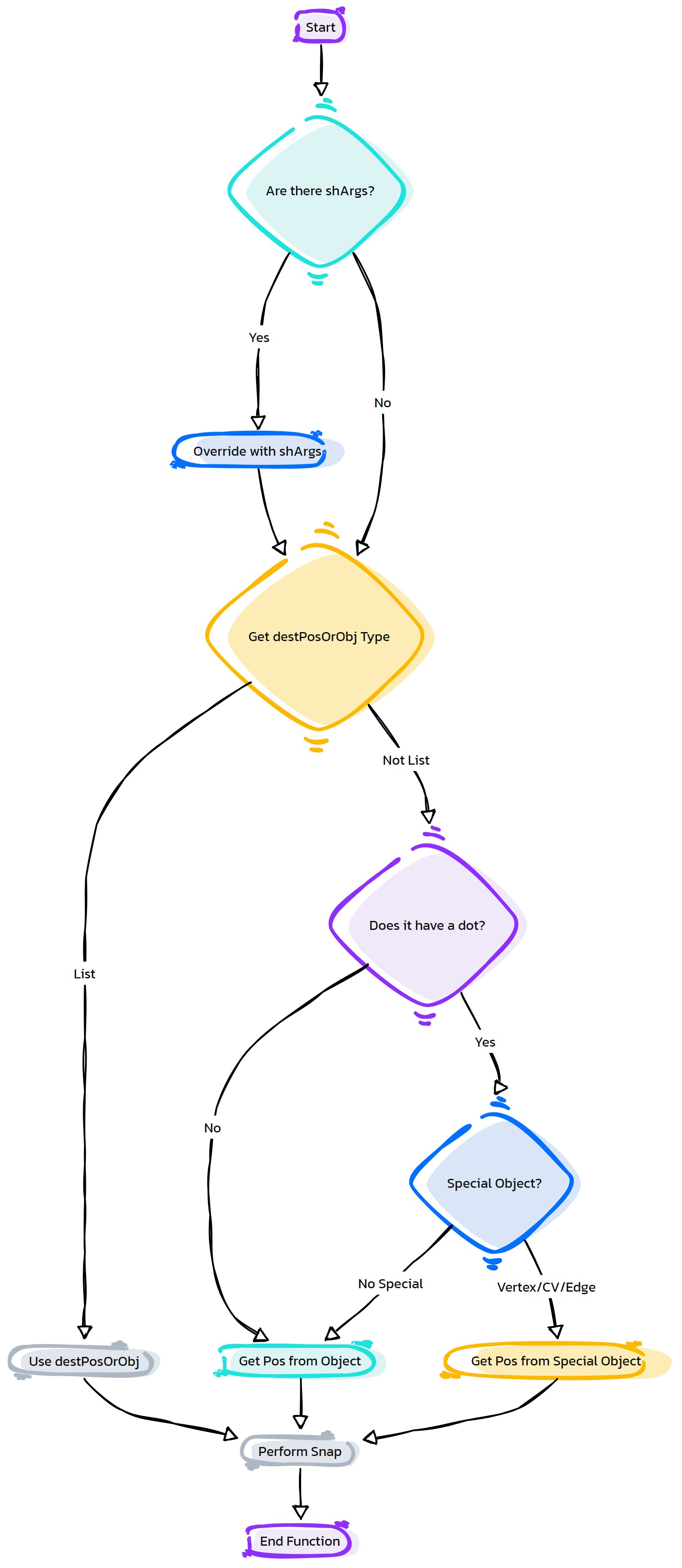
- eCtrl.snapWithOffset(self, ctrlGrp, refObj, attr, ratio, axisDirList, **shArgs)#
[shArgs: cg=ctrlGrp, ro=refObj, a=attr, r=ratio, adl=axisDirList]
Purpose:
:: Snaps a control group to a reference object with an offset in Autodesk Maya.
Facilitates precise positioning of control groups based on the attributes of another object.
Allows for customized offsetting along specified axis directions.
- Parameters:
ctrlGrp – <str> # Name of the control group to be snapped.
refObj – <str> # Name of the reference object used for snapping.
attr – <str> # Name of the attribute on the reference object to determine the offset.
ratio – <float> # Ratio to scale the attribute value for offset calculation.
axisDirList – <list/str> # Axis directions (‘x’, ‘-x’, ‘y’, ‘-y’, ‘z’, ‘-z’) for applying the offset.
- Returns:
None # Adjusts the position of the control group but does not return a value.
Code Examples:
>>> control_group = "ctrl_grp"
>>> reference_object = "locator1"
>>> attribute_name = "translateX"
>>> offset_ratio = 2.0
>>> snapWithOffset(control_group, reference_object, attribute_name, offset_ratio, "x")
# Snaps the control group to the reference object with a doubled offset along the X-axis.
graph TB Start[("fa:fa-play Start")] --> CheckInputs{"/fas:fa-question-circle Check Inputs"} CheckInputs --"If shArgs Exist"--> ParseShArgs["/fas:fa-cogs Parse shArgs"] CheckInputs --"If shArgs Does Not Exist"--> InitializeParameters["/fas:fa-wrench Initialize Parameters"] InitializeParameters --> SnapControlGroup{"/fas:fa-magnet Snap Control Group"} SnapControlGroup --"Snap control group to reference object"--> CalculateOffset{"/fas:fa-ruler-combined Calculate Offset"} CalculateOffset --"Calculate offset based on attribute and ratio"--> ApplyOffset[("/fas:fa-arrow-right Apply Offset")] ApplyOffset --"Move control group based on calculated offset and axis directions"--> End[("fas:fa-stop-circle End")] style Start fill:#00cc00,stroke:#000,stroke-width:3px style CheckInputs fill:#ffcc00,stroke:#000,stroke-width:2px style ParseShArgs fill:#ff9999,stroke:#000,stroke-width:2px style InitializeParameters fill:#99ccff,stroke:#000,stroke-width:2px style SnapControlGroup fill:#99ff99,stroke:#000,stroke-width:2px style CalculateOffset fill:#ffcc99,stroke:#000,stroke-width:2px style ApplyOffset fill:#ccffcc,stroke:#000,stroke-width:2px style End fill:#ff6666,stroke:#000,stroke-width:3px- Flow Chart Description:
This flowchart illustrates the snapWithOffset function:
Starts by checking if shArgs are provided. If they are, it parses the necessary arguments (ctrlGrp, refObj, attr, ratio, axisDirList).
If shArgs are not provided, initializes parameters with default or provided values.
Snaps the control group to the reference object.
Calculates the offset based on the specified attribute and ratio.
Applies the calculated offset to the control group based on the provided axis directions.
The function concludes after applying the offset to the control group.
- eCtrl.spineCtrl(self, ctrlName, grpLevel=1, ctrlShape='circle', **shArgs)#
[shArgs : cn=ctrlName, gl=grpLevel, cs=ctrlShape]
Purpose:
:: Creates a spine control in Autodesk Maya, offering customization for control name, group level, and control shape.
Essential for rigging the spine of characters, providing flexibility and control for animating torso movements.
Allows for diverse visual representation of the control through various shape options.
- Parameters:
ctrlName – <str> # The name for the spine control. This is a required parameter.
grpLevel – <int, optional> # Hierarchy level for grouping the control. Default is 1.
ctrlShape – <str, optional> # Shape of the spine control. Available options include ‘circle’, ‘snake’, ‘gold ring’, ‘star’, ‘one pin’, ‘arrow head’. Default is ‘circle’.
- Returns:
<list> # A list containing the control and its top group as Maya nodes, based on grpLevel.
Code Examples:
>>> control_name = "spineControl"
>>> group_level = 1
>>> control_shape = "circle"
>>> spine_control = spineCtrl(control_name, group_level, control_shape)
# Creates a spine control with specified name, group level, and shape.
graph TB Start[("fa:fa-play Start")] --> CheckShape{{"/fas:fa-question Check Shape"}} CheckShape --"Shape 'circle'"--> CreateCircle[("/fas:fa-circle Create Circle Shape")] CheckShape --"Shape 'snake'"--> CreateSnake[("/fas:fa-street-view Create Snake Shape")] CheckShape --"Shape 'gold ring'"--> CreateGoldRing[("/fas:fa-life-ring Create Gold Ring Shape")] CheckShape --"Shape 'star'"--> CreateStar[("/fas:fa-star Create Star Shape")] CheckShape --"Shape 'one pin'"--> CreateOnePin[("/fas:fa-map-pin Create One Pin Shape")] CheckShape --"Shape 'arrow head'"--> CreateArrowHead[("/fas:fa-arrow-alt-circle-down Create Arrow Head Shape")] CreateCircle --> FinalizeCtrl[("/fas:fa-cog Finalize Control")] CreateSnake --> FinalizeCtrl CreateGoldRing --> FinalizeCtrl CreateStar --> FinalizeCtrl CreateOnePin --> FinalizeCtrl CreateArrowHead --> FinalizeCtrl FinalizeCtrl --> End[("fas:fa-stop-circle End")] style Start fill:#00cc00,stroke:#000,stroke-width:3px style CheckShape fill:#ffcc00,stroke:#000,stroke-width:2px style CreateCircle fill:#ff9999,stroke:#000,stroke-width:2px style CreateSnake fill:#99ccff,stroke:#000,stroke-width:2px style CreateGoldRing fill:#ffcc66,stroke:#000,stroke-width:2px style CreateStar fill:#cc99ff,stroke:#000,stroke-width:2px style CreateOnePin fill:#99ff99,stroke:#000,stroke-width:2px style CreateArrowHead fill:#66ccff,stroke:#000,stroke-width:2px style FinalizeCtrl fill:#f0ad4e,stroke:#000,stroke-width:2px style End fill:#ff6666,stroke:#000,stroke-width:3px- Flow Chart Description:
This flowchart illustrates the spineCtrl function:
The process starts by checking the specified ctrlShape.
Depending on the ctrlShape, the function creates the control in the shape of a circle, snake, gold ring, star, one pin, or arrow head.
The control is then finalized by deleting history, grouping at the specified level, and applying control color.
Finally, the function returns a list containing the control and its top group as Maya nodes.
- eCtrl.spotCtrl(self, ctrlName=None, grpLevel=3, initRot=None, colorVal=None, ctrlType=1, **shArgs)#
[shArgs : cn=ctrlName, gl=grpLevel, ir=initRot, cv=colorVal, ct=ctrlType]
Purpose:
:: Creates a spot control in Autodesk Maya, resembling a locator but made with NURBS curves, customizable with control name, group level, initial rotation, color value, and control type.
- Parameters:
ctrlName – <str, optional> #Name for the spot control. Default is ‘as_Spot_Ctrl’.
grpLevel – <int, optional> #Specifies the hierarchy level for grouping the control. Default is 3.
initRot – <list, optional> #Initial rotation of the control, given as [x, y, z].
colorVal – <color, optional> #Color value to apply to the control.
ctrlType – <int, optional> #Type of spot control to be created. Options include different shapes. Default is 1.
- Returns:
<list> #A list containing the control and its top group as Maya nodes, based on grpLevel.
Usage:
ctrl                  =eCtrl.spotCtrl(ctrlName)[0]
ctrlGrp       =eCtrl.spotCtrl(ctrlName)[-1]
ctrl, ctrlGrp =eCtrl.spotCtrl(ctrlName)
graph TB Start[("fa:fa-play Start")] --> CheckShArgs{"/fas:fa-question-circle Check shArgs"} CheckShArgs --"If shArgs Exist"--> ParseShArgs["/fas:fa-cogs Parse shArgs"] CheckShArgs --"If shArgs Does Not Exist"--> InitializeParameters["/fas:fa-wrench Initialize Parameters"] InitializeParameters --> CreateSpotControl{"/fas:fa-pen-nib Create Spot Control"} ParseShArgs --"If shArgs Exist"--> CreateSpotControl CreateSpotControl --"Create Spot Control"--> RotateControl["/fas:fa-undo Rotate Control"] RotateControl --"Rotate Control if initRot Provided"--> CreateControlGroup{"/fas:fa-object-group Create Control Group"} CreateControlGroup --"Create Control Group"--> ApplyControlColor["/fas:fa-paint-brush Apply Control Color"] ApplyControlColor --"Apply Control Color"--> End["/fas:fa-stop End"] style Start fill:#00cc00,stroke:#000,stroke-width:3px style CheckShArgs fill:#ffcc00,stroke:#000,stroke-width:2px style ParseShArgs fill:#ff9999,stroke:#000,stroke-width:2px style InitializeParameters fill:#99ccff,stroke:#000,stroke-width:2px style CreateSpotControl fill:#ccffcc,stroke:#000,stroke-width:2px style RotateControl fill:#99ccff,stroke:#000,stroke-width:2px style CreateControlGroup fill:#99ccff,stroke:#000,stroke-width:2px style ApplyControlColor fill:#ffcc99,stroke:#000,stroke-width:2px style End fill:#ff6666,stroke:#000,stroke-width:3px- Flow Chart Description:
This flowchart illustrates the spotCtrl function:
Checks if shArgs exist and parses them if present.
Initializes parameters for control creation, including ctrlName, grpLevel, initRot, colorVal, and ctrlType.
Creates a spot control with the specified ctrlName and ctrlType.
Rotates the control if initRot is provided.
Creates a control group based on the grpLevel.
Applies control color to the control.
- eCtrl.squareCtrl(self, ctrlName=None, grpLevel=3, initRot=[0, 0, 0], ctrlType=1, **shArgs)#
[shArgs : cn=ctrlName, gl=grpLevel, ir=initRot, ct=ctrlType]
Purpose:
:: Provides a straightforward way to create square-shaped controls in Autodesk Maya, useful for various rigging tasks.
Square controls are often used for rigging features that require orthogonal or planar manipulation.
Customizable to fit different rigging needs through control name, grouping, rotation, and type options.
- Parameters:
ctrlName – <str, optional> # Designates the name for the square control. Defaults to ‘as_Square_Ctrl’ if not provided.
grpLevel – <int, optional> # Determines the control’s grouping hierarchy level, influencing its organizational structure. Default is 3.
initRot – <list, optional> # Sets the initial rotation of the control in [x, y, z] format. Default is [0, 0, 0].
ctrlType – <int, optional> # Specifies the type of square control, allowing for different design variations. Default is 1.
- Returns:
<list> # Returns a list comprising the square control and its top group as Maya nodes, determined by grpLevel.
Code Examples:
>>> square_control = squareCtrl(ctrlName="mySquareCtrl", grpLevel=2, ctrlType=1)
# Generates a square control with a specified name, group level, and control type.
graph TD Start[("fa:fa-play Start")] --> CheckShArgs{"/fas:fa-question-circle Check shArgs"} CheckShArgs --"If shArgs Exist"--> ParseShArgs["/fas:fa-cogs Parse shArgs"] CheckShArgs --"If shArgs Does Not Exist"--> InitializeParameters["/fas:fa-wrench Initialize Parameters"] InitializeParameters --> GenerateControl["/fas:fa-square Generate Control"] GenerateControl --> RotateControl["/fas:fa-redo Rotate Control"] RotateControl --> GroupControl["/fas:fa-object-group Group Control"] GroupControl --> ApplyColor["/fas:fa-paint-brush Apply Color"] ApplyColor --> End["/fas:fa-stop End"] style Start fill:#00cc00,stroke:#000,stroke-width:3px style CheckShArgs fill:#ffcc00,stroke:#000,stroke-width:2px style ParseShArgs fill:#ff9999,stroke:#000,stroke-width:2px style InitializeParameters fill:#99ccff,stroke:#000,stroke-width:2px style GenerateControl fill:#99ff99,stroke:#000,stroke-width:2px style RotateControl fill:#99ff99,stroke:#000,stroke-width:2px style GroupControl fill:#99ff99,stroke:#000,stroke-width:2px style ApplyColor fill:#99ff99,stroke:#000,stroke-width:2px style End fill:#ff6666,stroke:#000,stroke-width:3px- Flow Chart Description:
This flowchart illustrates the squareCtrl function:
Checks if shArgs exist, and if so, parses the function arguments from it.
If shArgs do not exist, initializes parameters with default values.
Generates a square-shaped control in Autodesk Maya based on the specified control type.
Rotates the control based on the initRot parameter.
Groups the control based on the grpLevel.
Applies color to the control using the applyCtrlColor method.
Ends the process.
- eCtrl.starCtrl(self, ctrlName=None, grpLevel=3, ctrlType=1, initRot=[0, 0, 0], snapPiv=1, grpSufxList=None, colorVal=None, **shArgs)#
[shArgs : cn=ctrlName, gl=grpLevel, ct=ctrlType, ir=initRot, sp=snapPiv, gsl=grpSufxList, cv=colorVal]
Purpose:
:: Creates a star-shaped control in Autodesk Maya, offering options for control name, group level, control type, initial rotation, pivot snapping, group suffix list, and color value.
This function provides extensive customization for creating star-shaped controls in Maya, making it versatile for various rigging and animation needs.
The function’s flexibility in specifying control type, initial rotation, pivot snapping, and other parameters allows for precise control creation as per user requirements.
- Parameters:
ctrlName – <str, optional> # Name for the star control.
grpLevel – <int, optional> # Hierarchy level for grouping the control. Default is 3.
ctrlType – <int, optional> # Type of star control to be created. Options include different shapes. Default is 1.
initRot – <list, optional> # Initial rotation of the control, given as [x, y, z]. Default is [0, 0, 0].
snapPiv – <bool, optional> # Whether to snap the control’s pivot. Default is 1.
grpSufxList – <list/str, optional> # Suffix list for the control’s groups.
colorVal – <color, optional> # Color value to apply to the control.
- Returns:
<list> # A list containing the control and its top group as Maya nodes, based on grpLevel.
graph TB Start[("fa:fa-play Start")] --> CheckInputs{"/fas:fa-question-circle Check Inputs"} CheckInputs --"Input Provided"--> CreateControl[("/fas:fa-star Create Star Control")] CreateControl --> GroupControl[("/fas:fa-object-group Group Control")] GroupControl --> ApplyColor[("/fas:fa-palette Apply Color")] ApplyColor --> End[("fas:fa-stop-circle End")] CheckInputs --"No Input"--> Error[("fa:fa-times Error")] style Start fill:#00cc00,stroke:#000,stroke-width:3px style CheckInputs fill:#ffcc00,stroke:#000,stroke-width:2px style CreateControl fill:#99ff99,stroke:#000,stroke-width:2px style GroupControl fill:#ff9999,stroke:#000,stroke-width:2px style ApplyColor fill:#99ccff,stroke:#000,stroke-width:2px style Error fill:#ff6666,stroke:#000,stroke-width:3px style End fill:#ff6666,stroke:#000,stroke-width:3px- Flow Chart Description:
This flowchart illustrates the starCtrl function:
The function begins by checking for provided inputs such as control name, group level, control type, initial rotation, pivot snapping, group suffix list, and color value.
If inputs are provided, a star-shaped control is created based on the specified parameters.
The control is grouped according to the hierarchy level specified.
Color is applied to the control for visual differentiation.
The process ends after successfully creating and configuring the star control.
If required inputs are missing, an error is indicated.
- eCtrl.transferAttrConnections(self)#
[shArgs]
Purpose:
:: Facilitates the transfer of attribute connections from one asNode to another within Autodesk Maya. This function is instrumental in duplicating control attributes, transferring rig setups, or managing dynamic attribute links.
Essential for maintaining scene integrity during complex rigging or scene modifications.
Allows for precise control over attribute connections, ensuring rig consistency and functionality.
- Suggested args:
sourceNode: <str> # The source asNode from which attribute connections are to be copied.
targetNode: <str> # The destination asNode to which attribute connections are to be transferred.
attributes: <list of str, optional> # Specific attributes for which connections should be transferred. If omitted, all connections may be transferred.
- Returns:
<str/bool> # A status message indicating the outcome of the transfer, or a boolean representing success (True) or failure (False).
Code Examples:
>>> result = transferAttrConnections(sourceNode="sourceCtrl", targetNode="targetCtrl", attributes=["translateX", "translateY"])
# Transfers specific attribute connections from 'sourceCtrl' to 'targetCtrl'.

>>> result = transferAttrConnections(sourceNode="oldRig", targetNode="newRig")
# Transfers all attribute connections from 'oldRig' to 'newRig'.
graph TB Start[("fa:fa-play Start")] --> CheckShArgs{"/fas:fa-question-circle Check shArgs"} CheckShArgs --"If shArgs Exist"--> InitializeParameters["/fas:fa-wrench Initialize Parameters"] CheckShArgs --"If shArgs Does Not Exist"--> SelectSourceAndTarget["/fas:fa-mouse-pointer Select Source and Target"] InitializeParameters --> GetSelectedObjects{"/fas:fa-check-square Get Selected Objects"} GetSelectedObjects --"For Each Selected Object"--> CheckAttribute{"/fas:fa-question-circle Check Attribute"} CheckAttribute --"If Attribute Exists"--> GetAttributeType["/fas:fa-info Get Attribute Type"] CheckAttribute --"If Attribute Does Not Exist"--> ErrorAttributeNotFound["/fas:fa-exclamation-triangle Error: Attribute Not Found"] GetAttributeType --"If Attribute Type is String"--> CreateStringAttribute["/fas:fa-plus Create String Attribute"] GetAttributeType --"If Attribute Type is Enum"--> WarningEnumAttribute["/fas:fa-exclamation-triangle Warning: Unable to create Enum Attribute"] GetAttributeType --"If Attribute Type is Other"--> CreateNumericAttribute["/fas:fa-plus Create Numeric Attribute"] CreateStringAttribute --> SetStringValue["/fas:fa-pen-nib Set String Value"] CreateNumericAttribute --> SetNumericValue["/fas:fa-pen-nib Set Numeric Value"] SetStringValue --"Set String Value"--> End["/fas:fa-stop End"] SetNumericValue --"Set Numeric Value"--> End WarningEnumAttribute --> End ErrorAttributeNotFound --> End End --> CheckConnections{"/fas:fa-question-circle Check Connections"} CheckConnections --"If Connections Exist"--> TransferAttributeConnections["/fas:fa-arrow-right Transfer Attribute Connections"] CheckConnections --"If No Connections Exist"--> End["/fas:fa-stop End"] style Start fill:#00cc00,stroke:#000,stroke-width:3px style CheckShArgs fill:#ffcc00,stroke:#000,stroke-width:2px style InitializeParameters fill:#99ccff,stroke:#000,stroke-width:2px style SelectSourceAndTarget fill:#cc99ff,stroke:#000,stroke-width:2px style GetSelectedObjects fill:#cc99ff,stroke:#000,stroke-width:2px style CheckAttribute fill:#99ff99,stroke:#000,stroke-width:2px style ErrorAttributeNotFound fill:#ff9999,stroke:#000,stroke-width:2px style GetAttributeType fill:#99ccff,stroke:#000,stroke-width:2px style WarningEnumAttribute fill:#ff9999,stroke:#000,stroke-width:2px style CreateStringAttribute fill:#ccffcc,stroke:#000,stroke-width:2px style CreateNumericAttribute fill:#ccffcc,stroke:#000,stroke-width:2px style SetStringValue fill:#99ff99,stroke:#000,stroke-width:2px style SetNumericValue fill:#99ff99,stroke:#000,stroke-width:2px style End fill:#ff6666,stroke:#000,stroke-width:3px- Flow Chart Description:
This flowchart illustrates the transferAttrConnections function:
Checks if shArgs exist, and if not, it prompts the user to select source and target nodes.
Initializes parameters and retrieves a list of selected objects.
For each selected object, it checks if the specified attribute exists.
If the attribute exists, it determines its type.
If the attribute type is string, it creates a string attribute and sets its value.
If the attribute type is enum, it issues a warning as enum attributes cannot be transferred.
If the attribute type is other, it creates a numeric attribute and sets its value.
Checks if connections exist between the source and target nodes.
If connections exist, it transfers attribute connections.
If no connections exist, the process ends.
Note: Enum attributes cannot be transferred, and a warning is issued if encountered.
- eCtrl.triangleCtrl(self, ctrlName=None, grpLevel=3, initRot=[0, 0, 0], ctrlType=1, **shArgs)#
[shArgs : ctrlName=n, grpLevel=gl, initRot=ir, ctrlType=ct]
Purpose:
:: Constructs a triangle control in Autodesk Maya. Offers customization in control name, group level, initial rotation, and control type for diverse rigging scenarios.
Ideal for rig-related applications where triangular shapes are preferred for control handles.
Provides flexibility in control appearance and behavior, enhancing user interaction with the rig.
- Parameters:
ctrlName – <str, optional> # Name for the triangle control. Defaults to ‘as_Triangle_Ctrl’.
grpLevel – <int, optional> # Hierarchy level for grouping the control. Default is 3.
initRot – <list of float, optional> # Initial rotation of the control, specified as [x, y, z]. Default is [0, 0, 0].
ctrlType – <int, optional> # Determines the shape of the triangle control. Options include different triangle shapes. Default is 1.
- Returns:
<list of asNode> # A list with the control and its top group as Maya nodes, based on grpLevel.
Usage Examples:
>>> triangle_control = triangleCtrl(ctrlName="myTriangleCtrl", ctrlType=1)[0]
# Creates a standard triangle control with default settings.

>>> triangle_control, triangle_control_group = triangleCtrl(ctrlName="customTriangle", ctrlType=2, grpLevel=2)
# Creates a custom triangle control with a specific group level and control type.
graph TB Start[("fa:fa-play Start")] --> CheckShArgs{"/fas:fa-question-circle Check shArgs"} CheckShArgs --"If shArgs Exist"--> ParseShArgs["/fas:fa-cogs Parse shArgs"] CheckShArgs --"If shArgs Does Not Exist"--> InitializeParameters["/fas:fa-wrench Initialize Parameters"] InitializeParameters --> CreateTriangleControl{"/fas:fa-pen-nib Create Triangle Control"} ParseShArgs --"If shArgs Exist"--> CreateTriangleControl CreateTriangleControl --> RotateTriangleControl["/fas:fa-sync Rotate Triangle Control"] RotateTriangleControl --"Rotate Triangle Control"--> FreezeTriangleControl["/fas:fa-snowflake Freeze Triangle Control"] FreezeTriangleControl --"Freeze Triangle Control"--> DeleteHistory["/fas:fa-trash-alt Delete History"] DeleteHistory --"Delete History"--> CreateControlGroup{"/fas:fa-object-group Create Control Group"} CreateControlGroup --"Create Control Group"--> ApplyControlColor["/fas:fa-paint-brush Apply Control Color"] ApplyControlColor --"Apply Control Color"--> End["/fas:fa-stop End"] style Start fill:#00cc00,stroke:#000,stroke-width:3px style CheckShArgs fill:#ffcc00,stroke:#000,stroke-width:2px style ParseShArgs fill:#ff9999,stroke:#000,stroke-width:2px style InitializeParameters fill:#99ccff,stroke:#000,stroke-width:2px style CreateTriangleControl fill:#ccffcc,stroke:#000,stroke-width:2px style RotateTriangleControl fill:#ccffcc,stroke:#000,stroke-width:2px style FreezeTriangleControl fill:#99ff99,stroke:#000,stroke-width:2px style DeleteHistory fill:#cc99ff,stroke:#000,stroke-width:2px style CreateControlGroup fill:#99ccff,stroke:#000,stroke-width:2px style ApplyControlColor fill:#ffcc99,stroke:#000,stroke-width:2px style End fill:#ff6666,stroke:#000,stroke-width:3px- Flow Chart Description:
This flowchart illustrates the triangleCtrl function:
Checks if shArgs exist and parses them if present.
Initializes parameters for control creation, including ctrlName, grpLevel, initRot, and ctrlType.
Creates a triangle control based on the specified ctrlType.
Rotates the triangle control based on the provided initRot values.
Freezes the transformations of the control.
Deletes the history of the control.
Creates a control group based on the grpLevel.
Applies control color to the control.