
EasyQuad#
- EasyQuad.__confirmAction(self, action)#
- EasyQuad.__init__(self)#
as_EasyQuadMain_v1.0
About :#
Author: (Subbaiah) Subbu Addanki Character Supervisor (Rigging) & Programmer
Visit :#
Contact :#
Mail Id: subbu.add@gmail.com Mobile No: +91-9741454400 / +91-9949005359
Copyright (c) as_EasyQuadMain :#
** (Subbaiah) Subbu Addanki. All Rights Reserved. **
- EasyQuad._compileEasyQuad(self, userFolder='$_Free_EasyQuad_v1.0')#
- EasyQuad._isInTime(self, startDate=[2017, 1, 1], endDate=[2018, 1, 1], onlineTime=1, showDaysLeft=1, bufferTime=1)#
- EasyQuad._mayaVer(self)#
- EasyQuad.add_BindJntsForGameEngine(self)#
[shArgs : None]
Purpose:
:: Generates bind joints suitable for game engine rigging in Autodesk Maya.
This function dynamically creates bind joints based on the current rig setup, focusing on essential areas like the cog, chest, and head if they are enabled.
Aimed at streamlining the process of preparing a rig for game engine compatibility, especially in terms of joint hierarchy and structure.
- Parameters:
None – No parameters are required for this function.
- Returns:
None # This function does not return a value but creates and organizes bind joints within the rig for game engine use.
Code Examples:
>>> add_BindJntsForGameEngine()
# Creates and organizes bind joints for game engine rigging.
graph TB Start[("fa:fa-play Start")] --> CheckToes{"/fas:fa-question-circle Check Create Toes"} CheckToes --"If Create Toes Enabled"--> OverrideHeadNeck{"/fas:fa-exchange-alt Override Head-Neck"} OverrideHeadNeck --"Override Applied"--> GenerateJoints{"/fas:fa-sitemap Generate Bind Joints"} CheckToes --"Create Toes Disabled"--> GenerateJoints GenerateJoints --"Joints Generated"--> CheckRearLegs{"/fas:fa-question-circle Check Rear Legs"} CheckRearLegs --"If Rear Legs Enabled"--> OverrideCogRoot{"/fas:fa-exchange-alt Override COG-Root"} OverrideCogRoot --"Override Applied"--> AddToList{"/fas:fa-plus-square Add to Joint List"} CheckRearLegs --"Rear Legs Disabled"--> CheckFrontLegs CheckFrontLegs --"If Front Legs Enabled"--> OverrideChestSpine{"/fas:fa-exchange-alt Override Chest-Spine"} OverrideChestSpine --"Override Applied"--> AddToList CheckFrontLegs --"Front Legs Disabled"--> CheckNeckHead CheckNeckHead --"If Neck-Head Enabled"--> OverrideHeadNeck CheckNeckHead --"Neck-Head Disabled"--> AddToList AddToList --"Joints Added"--> CreateDeformJoints{"/fas:fa-bone Create Deform Joints"} CreateDeformJoints --"Deform Joints Created"--> End["/fas:fa-stop End"] style Start fill:#00cc00,stroke:#000,stroke-width:3px style CheckToes fill:#ffcc00,stroke:#000,stroke-width:2px style OverrideHeadNeck fill:#99ccff,stroke:#000,stroke-width:2px style GenerateJoints fill:#ff9999,stroke:#000,stroke-width:2px style CheckRearLegs fill:#ffcc00,stroke:#000,stroke-width:2px style OverrideCogRoot fill:#99ccff,stroke:#000,stroke-width:2px style AddToList fill:#99ff99,stroke:#000,stroke-width:2px style CheckFrontLegs fill:#ffcc00,stroke:#000,stroke-width:2px style OverrideChestSpine fill:#99ccff,stroke:#000,stroke-width:2px style CheckNeckHead fill:#ffcc00,stroke:#000,stroke-width:2px style CreateDeformJoints fill:#cc99ff,stroke:#000,stroke-width:2px style End fill:#ff6666,stroke:#000,stroke-width:3px- Flow Chart Description:
This flowchart illustrates the add_BindJntsForGameEngine function:
The function starts by checking if ‘Create Toes’ is enabled.
If enabled, it overrides the connection between the head and neck joints.
Proceeds to generate necessary bind joints.
Checks if rear legs setup is enabled and applies overrides between cog and root joints if true.
Checks if front legs setup is enabled and applies overrides between chest and spine end joints if true.
Checks if neck and head setup is enabled and applies overrides between head and neck end joints if true.
Adds all the necessary joints to a list for deform joint creation.
Creates deform joints and adds them to the appropriate group.
The function concludes after the deform joints are created.
- EasyQuad.add_Selection(self, textFld, multiSelect=False)#
Adds selected object’s name as Input in any Window for <== button Usage: —— obj10 # Adds ‘obj10’ While pressing Enter.. <== button box25 # Adds ‘box25’ While pressing Enter.. <== button
- EasyQuad.applyCharPrefix(self)#
[shArgs : l=label, rM=rigMain]
Purpose:
:: Adds a specified prefix to all nodes within the hierarchy of a given main rig node in Autodesk Maya.
Enhances scene organization by allowing for consistent naming conventions across rig elements.
Facilitates easy identification of rig components belonging to a particular character or asset.
- Parameters:
label – <str> # The prefix to be applied to each node in the rig hierarchy.
rigMain – <PyNode> # The main rig node whose hierarchy is to be prefixed.
- Returns:
None # This function does not return a value but renames nodes within the rig hierarchy.
Code Examples:
>>> applyCharPrefix()
# Applies the given prefix to all nodes within the selected rig's hierarchy.
graph TB Start[("fa:fa-play Start")] --> CheckArgs{"/fas:fa-question-circle Check Arguments"} CheckArgs --"Arguments Provided"--> SelectHierarchy{"/fas:fa-sitemap Select Rig Hierarchy"} SelectHierarchy --"Select All Nodes in Hierarchy"--> ApplyPrefix{"/fas:fa-i-cursor Apply Prefix"} ApplyPrefix --"Prefix Applied to Each Node"--> End["/fas:fa-stop End"] style Start fill:#00cc00,stroke:#000,stroke-width:3px style CheckArgs fill:#ffcc00,stroke:#000,stroke-width:2px style SelectHierarchy fill:#99ccff,stroke:#000,stroke-width:2px style ApplyPrefix fill:#99ff99,stroke:#000,stroke-width:2px style End fill:#ff6666,stroke:#000,stroke-width:3px- Flow Chart Description:
This flowchart illustrates the applyCharPrefix function:
The function starts with checking the provided arguments.
It selects all nodes in the hierarchy of the specified rig main node.
Applies the provided prefix to each node in the selected hierarchy.
The function ends after renaming all nodes in the rig hierarchy.
- EasyQuad.as_AboutEasyQuad(self)#
[shArgs : None]
Purpose:
:: The as_AboutEasyQuad function displays information about the EasyQuad version 1.0, including the author’s details, contact information, copyrights, and special mentions.
Code Examples:
>>> as_AboutEasyQuad()
# This function presents a window with information about EasyQuad, including author, visit, contact details, and copyrights.
graph TB Start[("fa:fa-play Start")] --> CheckWindowExists{"/fas:fa-window-close Check if Window Exists"} CheckWindowExists -- "Yes" --> DeleteWindow[/fas:fa-trash Delete Existing Window/] DeleteWindow --> CheckMayaVersion{"/fas:fa-question Check Maya Version"} CheckWindowExists -- "No" --> CheckMayaVersion CheckMayaVersion -- "Version < 2016" --> LineTypeSingle[/fas:fa-minus Line Type: Single/] CheckMayaVersion -- "Version >= 2016" --> LineTypeDouble[/fas:fa-equals Line Type: Double/] LineTypeSingle --> CreateWindow[/fas:fa-window-maximize Create Information Window/] LineTypeDouble --> CreateWindow CreateWindow --> DisplayInfo[/fas:fa-info-circle Display Information/] DisplayInfo --> CloseButton{"/fas:fa-times-circle Close Button Clicked?"} CloseButton -- "Yes" --> DeleteWindowAfterDisplay[/fas:fa-trash-alt Delete Window/] CloseButton -- "No" --> AutoDeleteWindow[/fas:fa-clock Auto-Delete Window After 3 Sec/] AutoDeleteWindow --> End[("fas:fa-stop End")] style Start fill:#00cc00,stroke:#000,stroke-width:3px style CheckWindowExists fill:#ffcc00,stroke:#000,stroke-width:2px style DeleteWindow fill:#ff9999,stroke:#000,stroke-width:2px style CheckMayaVersion fill:#ffcc00,stroke:#000,stroke-width:2px style LineTypeSingle fill:#99ccff,stroke:#000,stroke-width:2px style LineTypeDouble fill:#99ccff,stroke:#000,stroke-width:2px style CreateWindow fill:#99ccff,stroke:#000,stroke-width:2px style DisplayInfo fill:#99ccff,stroke:#000,stroke-width:2px style CloseButton fill:#ffcc00,stroke:#000,stroke-width:2px style DeleteWindowAfterDisplay fill:#ff9999,stroke:#000,stroke-width:2px style AutoDeleteWindow fill:#ff9999,stroke:#000,stroke-width:2px style End fill:#ff6666,stroke:#000,stroke-width:3px- Flow Chart Description:
This flowchart illustrates the as_AboutEasyQuad function:
Checks if the information window already exists and deletes it if present.
Determines the line type based on the Maya version.
Creates a new information window to display EasyQuad details.
Displays information about EasyQuad, including author, contact, and copyright.
Provides options to close the window manually or auto-delete it after 3 seconds.
The process concludes by removing the information window and refreshing the view.
- EasyQuad.as_ActivateSetPose(self)#
[shArgs : l=label]
Purpose:
:: Activates and sets a pose for selected control objects in Autodesk Maya using an expression command.
Useful for creating reset or default poses for rig controls, allowing animators to quickly return to a base state.
Dynamically generates an expression to reset control attributes to their default values.
- Parameters:
label – <str> # Label used as a prefix to create unique identifiers for the expression command and script nodes.
- Returns:
None # This function does not return any value but creates an expression to set control poses.
Code Examples:
>>> as_ActivateSetPose(label="myCharacter")
# Activates and sets a pose for the selected controls of 'myCharacter' in Maya.
graph TB Start[("fa:fa-play Start")] --> CheckSelection{"/fas:fa-check-circle Check Selection"} CheckSelection --"If Selection Exists"--> InitializeVariables["/fas:fa-sliders-h Initialize Variables"] CheckSelection --"If No Selection"--> DisplayWarning["/fas:fa-exclamation-triangle Display Warning"] InitializeVariables --> CreateExpressionCommand["/fas:fa-code Create Expression Command"] CreateExpressionCommand --> GenerateResetAllProc["/fas:fa-recycle Generate ResetAll Procedure"] GenerateResetAllProc --"For Each Selected Node"--> IterateNodes["/fas:fa-repeat Iterate Through Nodes"] IterateNodes --> SetDefaultAttributes["/fas:fa-sliders-h Set Default Attributes"] SetDefaultAttributes --> AppendToExpression["/fas:fa-pencil-alt Append to Expression"] AppendToExpression --> IterateNodes IterateNodes --"After Last Node"--> CreateScriptNode["/fas:fa-sticky-note Create Script Node"] CreateScriptNode --> OpenExpressionEditor["/fas:fa-edit Open Expression Editor"] DisplayWarning --> End["/fas:fa-stop End"] OpenExpressionEditor --> End style Start fill:#00cc00,stroke:#000,stroke-width:3px style CheckSelection fill:#ffcc99,stroke:#000,stroke-width:2px style InitializeVariables fill:#99ccff,stroke:#000,stroke-width:2px style CreateExpressionCommand fill:#cc99ff,stroke:#000,stroke-width:2px style GenerateResetAllProc fill:#99ff99,stroke:#000,stroke-width:2px style IterateNodes fill:#ffcc99,stroke:#000,stroke-width:2px style SetDefaultAttributes fill:#ccffcc,stroke:#000,stroke-width:2px style AppendToExpression fill:#99ccff,stroke:#000,stroke-width:2px style CreateScriptNode fill:#cc99ff,stroke:#000,stroke-width:2px style OpenExpressionEditor fill:#ffcc99,stroke:#000,stroke-width:2px style DisplayWarning fill:#ff6666,stroke:#000,stroke-width:3px style End fill:#ff6666,stroke:#000,stroke-width:3px- Flow Chart Description:
This flowchart illustrates the as_ActivateSetPose function:
The process starts by checking if any objects are selected.
If no objects are selected, a warning is displayed.
If objects are selected, variables are initialized, including the label.
Creates the expression command based on the label and selected objects.
Generates a “ResetAll” procedure in the expression to reset attributes to default values.
Iterates through each selected node to set its default attributes in the expression.
Appends the attribute reset commands to the expression for each node.
After iterating through all nodes, creates a script node with the generated expression.
Opens the Expression Editor for further adjustments or review.
The process ends after setting up the expression and opening the Expression Editor.
- EasyQuad.as_AttachFeather(self)#
- EasyQuad.as_BasicSetup(self)#
[shArgs : rc=refCount, ct=createToes, qtf=quadTypeF, qtr=quadTypeR, clgf=createLegs_F]
Purpose:
:: Initializes a basic setup for rigging in Autodesk Maya by generating control curves, bones, and other rigging elements.
Streamlines the initial phase of rigging by automating the creation of essential rig components.
Allows for customization based on user inputs such as the number of references, toe creation, and leg types.
- Parameters:
refCount – <int> # Number of references for refreshing the view during the setup process.
createToes – <bool> # Determines whether toes are created as part of the rig.
quadTypeF – <str> # Specifies the type of front leg rig to create (e.g., ‘Quad’ or ‘Dinosaur’).
quadTypeR – <str> # Specifies the type of rear leg rig to create (e.g., ‘Quad’ or ‘Dinosaur’).
createLegs_F – <bool> # Determines whether front legs are created as part of the rig.
- Returns:
None # This function does not return a value but creates rigging elements in the Maya scene.
Code Examples:
>>> as_BasicSetup()
# Executes the basic rigging setup based on the specified parameters.
graph TB Start[("fa:fa-play Start")] --> Initialize{"/fas:fa-cogs Initialize Setup"} Initialize --"Setup Initialized"--> GenerateCurves{"/fas:fa-bezier-curve Generate Control Curves"} GenerateCurves --"Control Curves Generated"--> CreateBones{"/fas:fa-bone Create Bones"} CreateBones --"Bones Created"--> SetupConstraints{"/fas:fa-link Setup Constraints"} SetupConstraints --"Constraints Set"--> End["/fas:fa-stop End"] style Start fill:#00cc00,stroke:#000,stroke-width:3px style Initialize fill:#ffcc00,stroke:#000,stroke-width:2px style GenerateCurves fill:#99ccff,stroke:#000,stroke-width:2px style CreateBones fill:#ff9999,stroke:#000,stroke-width:2px style SetupConstraints fill:#99ff99,stroke:#000,stroke-width:2px style End fill:#ff6666,stroke:#000,stroke-width:3px- Flow Chart Description:
This flowchart illustrates the as_BasicSetup function:
The process begins with the initialization of the setup.
Generates control curves based on the specified leg types and toe creation option.
Creates bones for the rig structure.
Sets up constraints for rig control and manipulation.
The setup is completed, and the function ends.
- EasyQuad.as_BendySetup(self, baseJnt, bendyCount=4, elbowBendy=False, deleteUnwanted='hands', globalCtrl='Global_Control', bendySwitch=None, setup='hands')#
[shArgs : None]
Purpose:
:: The function as_BendySetup is used to create a sophisticated bendy rig setup for character limbs, allowing for smooth bending and twisting. This setup is crucial for achieving realistic deformations in character animation, especially in areas like elbows and shoulders or knees and hips.
Code Examples:
>>> as_BendySetup('L_Elbow_Jnt', bendyCount=4, elbowBendy=True, deleteUnwanted='hands', globalCtrl='Global_Control', bendySwitch ='L_IKFK_FLegSw', setup='hands')
# Configures a bendy rig for the left elbow joint with specific parameters like bendyCount, elbowBendy, and control options.
graph TB Start[("fa:fa-play Start")] --> InitSetup[/fas:fa-cogs Initialize Setup/] InitSetup --> RemoveUnwanted[/fas:fa-trash-alt Remove Unwanted Joints/] RemoveUnwanted --> CreateBaseJoints[/fas:fa-code-branch Create Base Joints/] CreateBaseJoints --> CreateBendySystem[/fas:fa-sitemap Create Bendy System/] CreateBendySystem --> CreateBendyCurve[/fas:fa-wave-square Create Bendy Curve/] CreateBendyCurve --> CreateBendyJoints[/fas:fa-network-wired Create Bendy Joints/] CreateBendyJoints --> SetupTwisterGroups[/fas:fa-sync-alt Setup Twister Groups/] SetupTwisterGroups --> CreateTangentConstraints[/fas:fa-ruler-combined Create Tangent Constraints/] CreateTangentConstraints --> ConnectTwistBalancers[/fas:fa-link Connect Twist Balancers/] ConnectTwistBalancers --> FinalizeSetup[/fas:fa-check-circle Finalize Setup/] FinalizeSetup --> End[("fas:fa-stop End")] style Start fill:#00cc00,stroke:#000,stroke-width:3px style InitSetup fill:#ff9999,stroke:#000,stroke-width:2px style RemoveUnwanted fill:#99ccff,stroke:#000,stroke-width:2px style CreateBaseJoints fill:#99ccff,stroke:#000,stroke-width:2px style CreateBendySystem fill:#99ccff,stroke:#000,stroke-width:2px style CreateBendyCurve fill:#ff9999,stroke:#000,stroke-width:2px style CreateBendyJoints fill:#99ccff,stroke:#000,stroke-width:2px style SetupTwisterGroups fill:#99ccff,stroke:#000,stroke-width:2px style CreateTangentConstraints fill:#99ccff,stroke:#000,stroke-width:2px style ConnectTwistBalancers fill:#99ccff,stroke:#000,stroke-width:2px style FinalizeSetup fill:#99ccff,stroke:#000,stroke-width:2px style End fill:#ff6666,stroke:#000,stroke-width:3px- Flow Chart Description:
This flowchart illustrates the as_BendySetup function:
The process begins with initializing the setup based on given parameters like base joint and global control.
It removes unwanted joints if specified, ensuring a clean setup.
The base joints are then created to form the primary structure for the bendy rig.
A bendy system, including groups for bending, twisting, and curves, is established.
A bendy curve is created to drive the deformation of the limb.
Bendy joints are then generated along this curve, allowing for smooth bending actions.
Twister groups are set up to manage the twisting of the bendy joints, providing additional control.
Tangent constraints are applied to align the bendy joints with the curve, ensuring proper deformation.
Twist balancers are connected to the joints, refining the twisting behavior of the rig.
The setup is finalized, integrating all components for effective bending and twisting of the limb.
- EasyQuad.as_BendySetup_Hands_FrontPV(self)#
[shArgs : None]
Purpose:
:: The function as_BendySetup_Hands_FrontPV focuses on creating bendy setups for the wrist and elbow joints of a character’s front paw/leg rig, enhancing rig flexibility and deformation.
Code Examples:
>>> as_BendySetup_Hands_FrontPV()
# Executes the bendy setup for the front paws/legs of a character rig, creating bendy controls for the wrist and elbow joints.
graph TB Start[("fa:fa-play Start")] --> BendySetupWrist1[("/fas:fa-bezier-curve Bendy Setup: L_Wrist_Jnt")] BendySetupWrist1 --> BendySetupElbow1[("/fas:fa-bezier-curve Bendy Setup: L_Elbow_Jnt")] BendySetupElbow1 --> BendySetupWrist2[("/fas:fa-bezier-curve Bendy Setup: R_Wrist_Jnt")] BendySetupWrist2 --> BendySetupElbow2[("/fas:fa-bezier-curve Bendy Setup: R_Elbow_Jnt")] BendySetupElbow2 --> End[("fas:fa-stop End")] style Start fill:#00cc00,stroke:#000,stroke-width:3px style BendySetupWrist1 fill:#99ccff,stroke:#000,stroke-width:2px style BendySetupElbow1 fill:#99ccff,stroke:#000,stroke-width:2px style BendySetupWrist2 fill:#99ccff,stroke:#000,stroke-width:2px style BendySetupElbow2 fill:#99ccff,stroke:#000,stroke-width:2px style End fill:#ff6666,stroke:#000,stroke-width:3px- Flow Chart Description:
This flowchart illustrates the as_BendySetup_Hands_FrontPV function:
The process begins with creating a bendy setup for the left wrist joint, incorporating bendy controls to enhance flexibility.
Proceeds to apply bendy setup for the left elbow joint, focusing on the non-elbow-bendy aspect.
Similar bendy setups are applied to the right wrist joint, adding dynamic controls for improved rig movements.
Completes the process by setting up bendy controls for the right elbow joint.
The process ends after successfully applying bendy setups to all specified joints.
- EasyQuad.as_BendySetup_Hands_RearPV(self)#
[shArgs : None]
Purpose:
:: The function as_BendySetup_Hands_RearPV is designed for creating bendy setups for the hands of a character rig. It handles different setups for quadruped and other characters by applying bendy controls to the elbow and shoulder joints.
Code Examples:
>>> as_BendySetup_Hands_RearPV()
# This example executes the bendy setup process for a character rig's hands, adjusting based on the character type (Quad or other).
graph TB Start[("fa:fa-play Start")] --> CheckQuadType[("/fas:fa-question Check Quad Type")] CheckQuadType --"If Quad" --> BendySetupQuad1[("/fas:fa-bezier-curve Bendy Setup: L_Elbow_Jnt")] BendySetupQuad1 --> BendySetupQuad2[("/fas:fa-bezier-curve Bendy Setup: L_Shoulder_Jnt")] BendySetupQuad2 --> BendySetupQuad3[("/fas:fa-bezier-curve Bendy Setup: R_Elbow_Jnt")] BendySetupQuad3 --> BendySetupQuad4[("/fas:fa-bezier-curve Bendy Setup: R_Shoulder_Jnt")] BendySetupQuad4 --> End[("fas:fa-stop End")] CheckQuadType --"If Not Quad" --> BendySetupNonQuad1[("/fas:fa-bezier-curve Bendy Setup: L_Elbow_Jnt")] BendySetupNonQuad1 --> BendySetupNonQuad2[("/fas:fa-bezier-curve Bendy Setup: L_Shoulder_Jnt")] BendySetupNonQuad2 --> BendySetupNonQuad3[("/fas:fa-bezier-curve Bendy Setup: R_Elbow_Jnt")] BendySetupNonQuad3 --> BendySetupNonQuad4[("/fas:fa-bezier-curve Bendy Setup: R_Shoulder_Jnt")] BendySetupNonQuad4 --> End style Start fill:#00cc00,stroke:#000,stroke-width:3px style CheckQuadType fill:#ffcc00,stroke:#000,stroke-width:2px style BendySetupQuad1 fill:#99ccff,stroke:#000,stroke-width:2px style BendySetupQuad2 fill:#99ccff,stroke:#000,stroke-width:2px style BendySetupQuad3 fill:#99ccff,stroke:#000,stroke-width:2px style BendySetupQuad4 fill:#99ccff,stroke:#000,stroke-width:2px style BendySetupNonQuad1 fill:#99ccff,stroke:#000,stroke-width:2px style BendySetupNonQuad2 fill:#99ccff,stroke:#000,stroke-width:2px style BendySetupNonQuad3 fill:#99ccff,stroke:#000,stroke-width:2px style BendySetupNonQuad4 fill:#99ccff,stroke:#000,stroke-width:2px style End fill:#ff6666,stroke:#000,stroke-width:3px- Flow Chart Description:
This flowchart illustrates the as_BendySetup_Hands_RearPV function:
The process starts by checking if the character is a quadruped.
- If it’s a quadruped (Quad), bendy setups are created for the left and right elbow and shoulder joints.
Creates a bendy setup for the left elbow joint.
Applies bendy controls to the left shoulder joint.
Sets up bendy features for the right elbow joint.
Adds bendy setup to the right shoulder joint.
- If it’s not a quadruped, similar bendy setups are applied but with different parameters.
Executes bendy setup for the left elbow joint.
Implements bendy controls for the left shoulder joint.
Conducts bendy setup for the right elbow joint.
Completes bendy setup for the right shoulder joint.
The process ends after completing all bendy setups.
- EasyQuad.as_BendySetup_Legs_FrontPV(self)#
[shArgs : None]
Purpose:
:: The function as_BendySetup_Legs_FrontPV is designed to create bendy setups for the hip and knee joints of a character’s rear leg rig. This function enhances the rig’s flexibility and deformation capabilities for different leg configurations.
Code Examples:
>>> as_BendySetup_Legs_FrontPV()
# Executes the bendy setup for the rear legs of a character rig, offering dynamic control over the hip and knee joints.
graph TB Start[("fa:fa-play Start")] --> CheckQuadType{{"/fas:fa-question Quad Type Check"}} CheckQuadType --"If Quad" --> BendySetupHip1[("/fas:fa-bezier-curve Bendy Setup: L_Hip_Jnt")] CheckQuadType --"Else" --> BendySetupKnee1[("/fas:fa-bezier-curve Bendy Setup: L_Knee_Jnt")] BendySetupHip1 --> BendySetupHip2[("/fas:fa-bezier-curve Bendy Setup: L_Hip2_Jnt")] BendySetupKnee1 --> BendySetupHip3[("/fas:fa-bezier-curve Bendy Setup: L_Hip_Jnt")] BendySetupHip2 --> BendySetupHip3[("/fas:fa-bezier-curve Bendy Setup: R_Hip_Jnt")] BendySetupHip3 --> BendySetupHip4[("/fas:fa-bezier-curve Bendy Setup: R_Hip2_Jnt")] BendySetupHip4 --> End[("fas:fa-stop End")] style Start fill:#00cc00,stroke:#000,stroke-width:3px style CheckQuadType fill:#ffcc00,stroke:#000,stroke-width:2px style BendySetupHip1 fill:#99ccff,stroke:#000,stroke-width:2px style BendySetupKnee1 fill:#99ccff,stroke:#000,stroke-width:2px style BendySetupHip2 fill:#99ccff,stroke:#000,stroke-width:2px style BendySetupHip3 fill:#99ccff,stroke:#000,stroke-width:2px style BendySetupHip4 fill:#99ccff,stroke:#000,stroke-width:2px style End fill:#ff6666,stroke:#000,stroke-width:3px- Flow Chart Description:
This flowchart illustrates the as_BendySetup_Legs_FrontPV function:
The process starts by checking the quad type of the character rig to determine the appropriate setup.
If the quad type is ‘Quad’, bendy setups are applied to the hip joints (L_Hip_Jnt and R_Hip_Jnt) and additional hip joints (L_Hip2_Jnt and R_Hip2_Jnt), providing enhanced control and flexibility.
Otherwise, bendy setups are applied to the knee joints (L_Knee_Jnt and R_Knee_Jnt) along with the hip joints (L_Hip_Jnt and R_Hip_Jnt), focusing on the dynamic rigging needs of non-quad characters.
The process concludes after successfully setting up bendy controls for the specified joints, tailoring to the specific leg configuration of the character.
- EasyQuad.as_BendySetup_Legs_RearPV(self)#
[shArgs : None]
Purpose:
:: The function as_BendySetup_Legs_RearPV establishes bendy setups for the rear wrist and rear elbow joints of a character’s leg rig. It is intended to improve the rig’s articulation and deformation in the rear legs.
Code Examples:
>>> as_BendySetup_Legs_RearPV()
# Executes the bendy setup for the rear legs' wrist and elbow joints, optimizing the rig for better animation control.
graph TB Start[("fa:fa-play Start")] --> BendySetupRearWrist1[("/fas:fa-bezier-curve Bendy Setup: L_RearWrist_Jnt")] BendySetupRearWrist1 --> BendySetupRearElbow1[("/fas:fa-bezier-curve Bendy Setup: L_RearElbow_Jnt")] BendySetupRearElbow1 --> BendySetupRearWrist2[("/fas:fa-bezier-curve Bendy Setup: R_RearWrist_Jnt")] BendySetupRearWrist2 --> BendySetupRearElbow2[("/fas:fa-bezier-curve Bendy Setup: R_RearElbow_Jnt")] BendySetupRearElbow2 --> End[("fas:fa-stop End")] style Start fill:#00cc00,stroke:#000,stroke-width:3px style BendySetupRearWrist1 fill:#99ccff,stroke:#000,stroke-width:2px style BendySetupRearElbow1 fill:#99ccff,stroke:#000,stroke-width:2px style BendySetupRearWrist2 fill:#99ccff,stroke:#000,stroke-width:2px style BendySetupRearElbow2 fill:#99ccff,stroke:#000,stroke-width:2px style End fill:#ff6666,stroke:#000,stroke-width:3px- Flow Chart Description:
This flowchart demonstrates the as_BendySetup_Legs_RearPV function:
It begins with setting up bendy controls for the left rear wrist joint (L_RearWrist_Jnt), enhancing rig flexibility and control.
Following the left wrist, a similar setup is applied to the left rear elbow joint (L_RearElbow_Jnt).
The process then moves to the right rear leg, starting with the right rear wrist joint (R_RearWrist_Jnt) for bendy setup.
Finally, the bendy setup is applied to the right rear elbow joint (R_RearElbow_Jnt), ensuring uniformity and dynamic control across both rear legs.
The function enhances the rig’s deformation capabilities, particularly in the wrist and elbow areas of the rear legs.
- EasyQuad.as_CleanLoc(self)#
[shArgs : ]
Purpose:
:: Deletes specific locators (‘dir_Loc’ and ‘vtx_Loc’) in Autodesk Maya, cleaning up the scene.
Used to remove unnecessary locators after they have served their purpose in rigging or animation tasks.
Helps maintain a tidy and efficient working environment within Maya.
- Returns:
None # This function does not return any value but removes specified locators from the scene.
Code Examples:
>>> as_CleanLoc()
# Deletes 'dir_Loc' and 'vtx_Loc' locators from the Maya scene.
graph TB Start[("fa:fa-play Start")] --> ConfirmDeletion{"/fas:fa-question-circle Confirm Deletion"} ConfirmDeletion --"If Confirmed"--> DeleteDirLoc["/fas:fa-trash-alt Delete 'dir_Loc'"] ConfirmDeletion --"If Not Confirmed"--> End["/fas:fa-stop End"] DeleteDirLoc --"Attempt Deletion"--> CheckVtxLoc{"/fas:fa-question-circle Check 'vtx_Loc' Existence"} CheckVtxLoc --"If 'vtx_Loc' Exists"--> DeleteVtxLoc["/fas:fa-trash-alt Delete 'vtx_Loc'"] CheckVtxLoc --"If 'vtx_Loc' Does Not Exist"--> End DeleteVtxLoc --> End style Start fill:#00cc00,stroke:#000,stroke-width:3px style ConfirmDeletion fill:#ffcc99,stroke:#000,stroke-width:2px style DeleteDirLoc fill:#99ccff,stroke:#000,stroke-width:2px style CheckVtxLoc fill:#cc99ff,stroke:#000,stroke-width:2px style DeleteVtxLoc fill:#99ff99,stroke:#000,stroke-width:2px style End fill:#ff6666,stroke:#000,stroke-width:3px- Flow Chart Description:
This flowchart illustrates the as_CleanLoc function:
The process starts by confirming with the user if they want to delete the locators.
If confirmed, the function attempts to delete the ‘dir_Loc’ locator.
After attempting to delete ‘dir_Loc’, it checks for the existence of ‘vtx_Loc’.
If ‘vtx_Loc’ exists, it proceeds to delete ‘vtx_Loc’.
The function ends after deleting the locators or if the user decides not to delete them.
- EasyQuad.as_ControlColors(self)#
[**shArgs : ct=colorType]
Purpose:
:: Customizes the colors of control objects in a rigging setup in Autodesk Maya.
This function streamlines the process of color-coding control objects for easier rigging and animation.
It changes all control colors to yellow, then adjusts left and right controls to blue and red (or alternate colors) respectively.
The function operates based on a color type option selected by the user, ensuring flexibility and customization.
It’s particularly useful in rigging workflows for visually organizing different control objects in a complex rig.
- Parameters:
colorType – <int> # The color type selected by the user, determining the color scheme for the control objects.
- Returns:
None # This function does not return a value but alters the color attributes of control objects in the Maya scene.
Code Examples:
>>> as_ControlColors()
# This will change the control colors based on the selected color type option in the Maya UI.
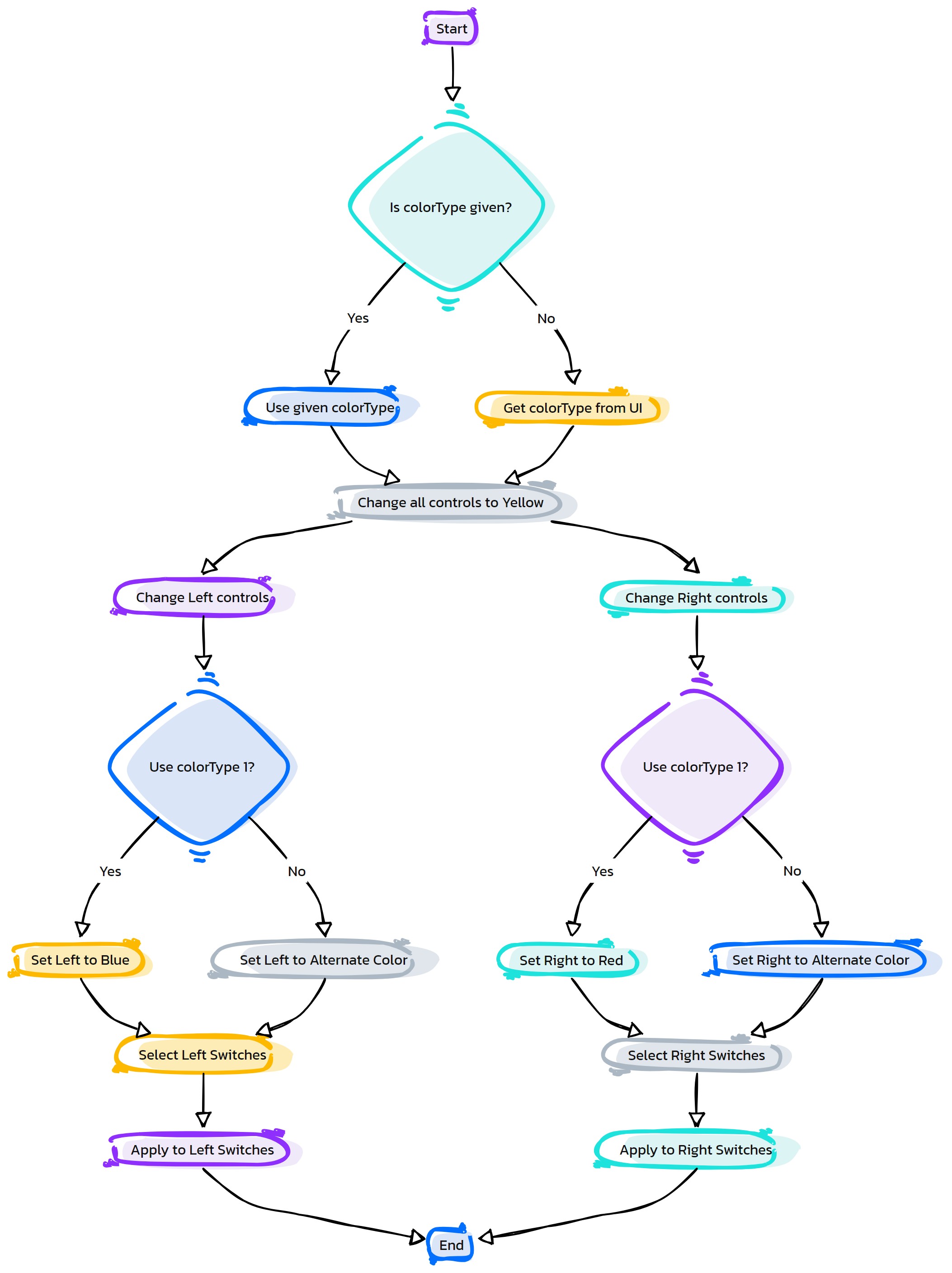
- Flow Chart Description:
This flowchart illustrates the as_ControlColors function:
The process starts by checking if a color type is provided. If not, it retrieves the color type from the Maya UI.
All control objects are initially set to a yellow color.
Left-side controls are then selected and set to blue or an alternate color based on the color type.
Right-side controls are selected next and set to red or pink, also depending on the color type.
The function ends after applying the specified colors to the controls.
- EasyQuad.as_CreateEyeSetup(self)#
[shArgs : None]
Purpose:
:: Constructs an eye rig in Autodesk Maya, creating skin joints and controls for the eyes and setting up aim constraints for realistic movement.
This function creates an eye rig that allows for individual control of each eye, as well as a main control for both eyes.
It sets up skin joints for the left and right eyes, aligns them to the eye geometry, and creates corresponding controls.
Aim constraints are used to ensure that the eyes follow the direction of the control objects, enabling lifelike eye animations.
- Returns:
None # The function constructs the eye rig but does not return any value.
Code Examples:
>>> as_CreateEyeSetup()
# This will create an eye rig with controls for left and right eyes, along with a main control for both.
graph TB Start[("fa:fa-play Start")] --> Init[("fas:fa-code Initialize Variables")] Init --> CreateSkinJoints[("fas:fa-bone Create Skin Joints for Eyes")] CreateSkinJoints --> CreateMainCtrl[("fas:fa-eye-slash Create Eyes Main Control")] CreateMainCtrl --> CreateLEyeCtrl[("fas:fa-eye Create Left Eye Control")] CreateLEyeCtrl --> CreateREyeCtrl[("fas:fa-eye Create Right Eye Control")] CreateREyeCtrl --> Finalize[("fas:fa-check-circle Finalize Setup")] Finalize --> End[("fas:fa-stop End")] style Start fill:#00cc00,stroke:#000,stroke-width:3px style Init fill:#ffcc00,stroke:#000,stroke-width:2px style CreateSkinJoints fill:#99ccff,stroke:#000,stroke-width:2px style CreateMainCtrl fill:#cc99ff,stroke:#000,stroke-width:2px style CreateLEyeCtrl fill:#ff9999,stroke:#000,stroke-width:2px style CreateREyeCtrl fill:#99ccff,stroke:#000,stroke-width:2px style Finalize fill:#cc99ff,stroke:#000,stroke-width:2px style End fill:#ff6666,stroke:#000,stroke-width:3px- Flow Chart Description:
The flowchart illustrates the as_CreateEyeSetup function:
Start: Initiates the eye rig setup process.
Initialize Variables: Prepares necessary variables for eye rig creation.
Create Skin Joints for Eyes: Sets up joints on each eye for rigging.
Create Eyes Main Control: Establishes a main control for both eyes.
Create Left Eye Control: Develops a control specifically for the left eye.
Create Right Eye Control: Constructs a control for the right eye.
Finalize Setup: Completes the setup of the eye rig.
End: Concludes the eye rigging process.
- EasyQuad.as_CreateEyeSetup_Old(self)#
- EasyQuad.as_CreateHandSetup(self)#
[shArgs : None]
Purpose:
:: The function as_CreateHandSetup orchestrates the setup of hand controls for a character rig, accommodating different types of quadrupeds (Quad and Dinosaur). It configures controls based on user-selected options like the type of quadruped, presence of toes, and the specific setup type (Front PV or Rear PV).
Code Examples:
>>> as_CreateHandSetup()
# This example executes the hand setup process for a character rig based on the user's selections in the interface options.
graph TB Start[("fa:fa-play Start")] --> CheckQuadType[("/fas:fa-question Check Quad Type")] CheckQuadType --"If quadTypeF is 'Quad'" --> CheckFrontLegsSetup[("/fas:fa-question Check Front Legs Setup")] CheckFrontLegsSetup --"If Front Legs Setup is checked" --> CheckSetupType[("/fas:fa-question Check Setup Type")] CheckSetupType --"If setupType is 'Front PV'" --> CreateHandSetupFrontPV[("/fas:fa-plus-circle Create Hand Setup Front PV")] CheckSetupType --"If setupType is 'Rear PV'" --> CreateHandSetupRearPV[("/fas:fa-plus-circle Create Hand Setup Rear PV")] CheckQuadType --"If quadTypeF is 'Dinosaur'" --> CreateHandsSetupDinosaur[("/fas:fa-paw Create Hands Setup Dinosaur")] CreateHandSetupFrontPV --> CheckBendyFrontLegs[("/fas:fa-question Check Bendy Front Legs")] CreateHandSetupRearPV --> CheckBendyFrontLegs CreateHandsSetupDinosaur --> End[("fas:fa-stop End")] CheckBendyFrontLegs --"If Bendy Front Legs and Bendy Setup All are checked" --> CheckSetupTypeBendy[("/fas:fa-question Check Setup Type for Bendy")] CheckSetupTypeBendy --"If setupType is 'Front PV'" --> BendySetupFrontPV[("/fas:fa-sitemap Bendy Setup Front PV")] CheckSetupTypeBendy --"If setupType is 'Rear PV'" --> BendySetupRearPV[("/fas:fa-sitemap Bendy Setup Rear PV")] BendySetupFrontPV --> CheckCreateToes[("/fas:fa-question Check Create Toes")] BendySetupRearPV --> CheckCreateToes CheckCreateToes --"If Create Toes is checked" --> CreateToesSetup[("/fas:fa-plus-circle Create Toes Setup")] style Start fill:#00cc00,stroke:#000,stroke-width:3px style CheckQuadType fill:#ffcc00,stroke:#000,stroke-width:2px style CheckFrontLegsSetup fill:#ffcc00,stroke:#000,stroke-width:2px style CheckSetupType fill:#ffcc00,stroke:#000,stroke-width:2px style CreateHandSetupFrontPV fill:#99ccff,stroke:#000,stroke-width:2px style CreateHandSetupRearPV fill:#99ccff,stroke:#000,stroke-width:2px style CreateHandsSetupDinosaur fill:#99ccff,stroke:#000,stroke-width:2px style CheckBendyFrontLegs fill:#ffcc00,stroke:#000,stroke-width:2px style CheckSetupTypeBendy fill:#ffcc00,stroke:#000,stroke-width:2px style BendySetupFrontPV fill:#cc99ff,stroke:#000,stroke-width:2px style BendySetupRearPV fill:#cc99ff,stroke:#000,stroke-width:2px style CheckCreateToes fill:#ffcc00,stroke:#000,stroke-width:2px style CreateToesSetup fill:#99ccff,stroke:#000,stroke-width:2px style End fill:#ff6666,stroke:#000,stroke-width:3px- Flow Chart Description:
This flowchart illustrates the as_CreateHandSetup function:
The process starts by determining the quadruped type (Quad or Dinosaur) based on the ‘quadTypeF’ option.
- If the type is ‘Quad’, it checks if the front legs setup is selected.
If selected, it determines the setup type (Front PV or Rear PV) and calls the corresponding hand setup function.
Additionally, it checks for bendy front legs setup and executes the appropriate bendy setup and shoulder control creation based on the setup type.
If the type is ‘Dinosaur’, it executes the dinosaur-specific hands setup.
Lastly, if the ‘createToes’ option is checked, it proceeds to create toe setups.
- EasyQuad.as_CreateHandSetup_FrontPV(self)#
[shArgs : None]
Purpose:
:: The function as_CreateHandSetup_FrontPV is designed to automate the process of setting up hand controls for front legs (presumably for quadruped characters) in Autodesk Maya. It involves creating various joints, IK handles, FK controls, and necessary constraints to facilitate animation.
Code Examples:
>>> as_CreateHandSetup_FrontPV()
# This example sets up the hand controls for front legs, including IK/FK switches, reverse foot setup, auto clavicle, and bank setup.
graph TB Start[("fa:fa-play Start")] --> InitializeVars[("/fas:fa-cogs Initialize Variables")] InitializeVars --> CreateJointNames[("/fas:fa-sitemap Create Joint Names")] CreateJointNames --> SetupChestJnt[("/fas:fa-user-md Setup Chest Joint")] SetupChestJnt --> CreateJoints[("/fas:fa-plus-circle Create Joints")] CreateJoints --> DuplicateJoints[("/fas:fa-clone Duplicate Joints")] DuplicateJoints --> CreateIKFKMix[("/fas:fa-exchange-alt Create IKFK Mix")] CreateIKFKMix --> CreateToes[("/fas:fa-plus-square Create Toes")] CreateToes --> MirrorJoints[("/fas:fa-arrows-alt-h Mirror Joints")] MirrorJoints --> CreateIKHandles[("/fas:fa-hand-rock Create IK Handles")] CreateIKHandles --> CreateIKFKSwitch[("/fas:fa-toggle-on Create IKFK Switch")] CreateIKFKSwitch --> CreateFKCtrls[("/fas:fa-hand-paper Create FK Controls")] CreateFKCtrls --> ReverseFootSetup[("/fas:fa-undo-alt Reverse Foot Setup")] ReverseFootSetup --> CreateFootControls[("/fas:fa-shoe-prints Create Foot Controls")] CreateFootControls --> ConnectRF[("/fas:fa-link Connect Reverse Foot")] ConnectRF --> CreatePoleCtrl[("/fas:fa-compass Create Pole Controls")] CreatePoleCtrl --> SetupIKFKConnections[("/fas:fa-code-branch Setup IKFK Connections")] SetupIKFKConnections --> CreateAutoClavicle[("/fas:fa-magic Create Auto Clavicle")] CreateAutoClavicle --> CreateClavicleCtrl[("/fas:fa-hand-spock Create Clavicle Control")] CreateClavicleCtrl --> CreateBankSetup[("/fas:fa-bank Create Bank Setup")] CreateBankSetup --> CreateRFEndCtrls[("/fas:fa-shoe-prints Create Reverse Foot End Controls")] CreateRFEndCtrls --> CreateAnkleRoll[("/fas:fa-ankh Create Ankle Roll Setup")] CreateAnkleRoll --> End[("fas:fa-stop End")] style Start fill:#00cc00,stroke:#000,stroke-width:3px style InitializeVars fill:#ff9999,stroke:#000,stroke-width:2px style CreateJointNames fill:#99ccff,stroke:#000,stroke-width:2px style SetupChestJnt fill:#ffcc00,stroke:#000,stroke-width:2px style CreateJoints fill:#99ccff,stroke:#000,stroke-width:2px style DuplicateJoints fill:#99ccff,stroke:#000,stroke-width:2px style CreateIKFKMix fill:#99ccff,stroke:#000,stroke-width:2px style CreateToes fill:#99ccff,stroke:#000,stroke-width:2px style MirrorJoints fill:#99ccff,stroke:#000,stroke-width:2px style CreateIKHandles fill:#99ccff,stroke:#000,stroke-width:2px style CreateIKFKSwitch fill:#99ccff,stroke:#000,stroke-width:2px style CreateFKCtrls fill:#99ccff,stroke:#000,stroke-width:2px style ReverseFootSetup fill:#99ccff,stroke:#000,stroke-width:2px style CreateFootControls fill:#99ccff,stroke:#000,stroke-width:2px style ConnectRF fill:#99ccff,stroke:#000,stroke-width:2px style CreatePoleCtrl fill:#99ccff,stroke:#000,stroke-width:2px style SetupIKFKConnections fill:#99ccff,stroke:#000,stroke-width:2px style CreateAutoClavicle fill:#99ccff,stroke:#000,stroke-width:2px style CreateClavicleCtrl fill:#99ccff,stroke:#000,stroke-width:2px style CreateBankSetup fill:#99ccff,stroke:#000,stroke-width:2px style CreateRFEndCtrls fill:#99ccff,stroke:#000,stroke-width:2px style CreateAnkleRoll fill:#99ccff,stroke:#000,stroke-width:2px style End fill:#ff6666,stroke:#000,stroke-width:3px- Flow Chart Description:
This flowchart illustrates the as_CreateHandSetup_FrontPV function:
Begins with initializing necessary variables and setting up joint names for the hands.
Configures chest joint to align with hand controls.
Creates joints for hands and duplicates joints for FK, IK, and Auto systems.
Implements an IK/FK mix setup for flexible control between IK and FK systems.
Optionally creates toes if specified.
Mirrors joints from one side to the other for symmetry.
Sets up IK handles for hand control.
Develops an IK/FK switch to toggle between IK and FK modes easily.
Creates FK controls for more direct control over the joints.
Sets up a reverse foot configuration for detailed foot control.
Establishes foot controls for animation.
Connects the reverse foot setup to the main controls.
Introduces pole vector controls for IK handles.
Sets up connections between IK and FK systems for seamless transitions.
Implements auto clavicle for automated shoulder movement.
Creates clavicle controls for additional manipulation.
Develops a banking system for the feet for more dynamic foot movements.
Creates end controls for reverse foot setup. 19. Concludes with an ankle roll setup for further foot control.
- EasyQuad.as_CreateHandSetup_RearPV(self)#
[shArgs : None]
Purpose:
:: The function as_CreateHandSetup_RearPV is designed to establish a comprehensive rig setup for the hands of a character, particularly focusing on the rear leg positions in a quadruped model. This setup includes the creation of various joint chains, IK/FK switches, control setups, and reverse foot mechanisms.
Code Examples:
>>> as_CreateHandSetup_RearPV()
# Executes the comprehensive rig setup for the hands of a character in a rear leg position, creating joint chains, IK/FK switches, control setups, and reverse foot mechanisms.
graph TB Start[("fa:fa-play Start")] --> CreateBaseSetup[/fas:fa-sitemap Create Base Setup/] CreateBaseSetup --> CreateJoints[/fas:fa-network-wired Create Joints/] CreateJoints --> SetupElbowAlign[("/fas:fa-ruler-combined Setup Elbow Alignment/")] SetupElbowAlign --> DuplicateJoints[/fas:fa-clone Duplicate Joints/] DuplicateJoints --> CreateIKFKMix[/fas:fa-exchange-alt Create IKFK Mix/] CreateIKFKMix --> CreateIKHandles[/fas:fa-hands Create IK Handles/] CreateIKHandles --> CreateIKFKSwitches[/fas:fa-toggle-on Create IKFK Switches/] CreateIKFKSwitches --> CreateFKCtrls[/fas:fa-hand-rock Create FK Controls/] CreateFKCtrls --> CreateReverseFoot[/fas:fa-undo-alt Create Reverse Foot Setup/] CreateReverseFoot --> CreateFootCtrls[/fas:fa-shoe-prints Create Foot Controls/] CreateFootCtrls --> CreatePoleCtrls[/fas:fa-location-arrow Create Pole Controls/] CreatePoleCtrls --> SetupIKFKVisibility[/fas:fa-eye-slash Setup IKFK Visibility/] SetupIKFKVisibility --> CreateClavicleCtrls[/fas:fa-ellipsis-v Create Clavicle Controls/] CreateClavicleCtrls --> CreateFootBank[/fas:fa-balance-scale-left Create Foot Bank Setup/] CreateFootBank --> CreateAnkleRoll[/fas:fa-circle-notch Create Ankle Roll Setup/] CreateAnkleRoll --> End[("fas:fa-stop End")] style Start fill:#00cc00,stroke:#000,stroke-width:3px style CreateBaseSetup fill:#ff9999,stroke:#000,stroke-width:2px style CreateJoints fill:#99ccff,stroke:#000,stroke-width:2px style SetupElbowAlign fill:#99ccff,stroke:#000,stroke-width:2px style DuplicateJoints fill:#99ccff,stroke:#000,stroke-width:2px style CreateIKFKMix fill:#ff9999,stroke:#000,stroke-width:2px style CreateIKHandles fill:#99ccff,stroke:#000,stroke-width:2px style CreateIKFKSwitches fill:#99ccff,stroke:#000,stroke-width:2px style CreateFKCtrls fill:#99ccff,stroke:#000,stroke-width:2px style CreateReverseFoot fill:#99ccff,stroke:#000,stroke-width:2px style CreateFootCtrls fill:#99ccff,stroke:#000,stroke-width:2px style CreatePoleCtrls fill:#99ccff,stroke:#000,stroke-width:2px style SetupIKFKVisibility fill:#99ccff,stroke:#000,stroke-width:2px style CreateClavicleCtrls fill:#99ccff,stroke:#000,stroke-width:2px style CreateFootBank fill:#99ccff,stroke:#000,stroke-width:2px style CreateAnkleRoll fill:#99ccff,stroke:#000,stroke-width:2px style End fill:#ff6666,stroke:#000,stroke-width:3px- Flow Chart Description:
This flowchart outlines the as_CreateHandSetup_RearPV function:
The process starts with establishing a base setup for the hand rig, including global control creation.
Next, it generates joints based on a defined curve, creating a base for the hand’s skeletal structure.
The elbow alignment is set up for better joint rotation and animation control.
Duplicate joint chains for FK, IK, and Auto setup are created, ensuring flexibility in animation.
IK/FK mixing joints are set up for smooth transitions between IK and FK controls.
IK handles are created for dynamic control of the hand rig.
IK/FK switches are established for seamless switching between IK and FK modes.
FK controls are generated for manipulating FK joint chains.
Reverse foot setup is created, allowing for more natural foot movement.
Foot controls are set up for detailed foot animations.
Pole controls are established to control the knee direction in IK mode.
IK/FK visibility setup is applied, controlling the visibility of respective controls based on the active mode.
Clavicle controls are created to manage shoulder and clavicle movement.
Foot bank setup is implemented for foot banking actions.
Ankle roll setup is finalized to enhance foot rolling movements.
- EasyQuad.as_CreateHandsSetup(self)#
[shArgs : None]
Purpose:
:: The function as_CreateHandsSetup is responsible for setting up the hands of a character rig. It involves creating joints, IK handles, FK controls, IK-FK switch, and if selected, toe setups for both left and right hands.
Code Examples:
>>> as_CreateHandsSetup()
# This example executes the hands setup process for a character rig, based on predefined global variables and user selections.
graph TB Start[("fa:fa-play Start")] --> CreateJoints[("/fas:fa-bone Create Joints from Curve")] CreateJoints --> AlignElbowJoint[("/fas:fa-ruler-combined Align Elbow Joint")] AlignElbowJoint --> DuplicateJoints[("/fas:fa-copy Duplicate FK, IK & Auto Joints")] DuplicateJoints --> CreateIKFKMixJoints[("/fas:fa-sitemap Create IKFK Mix Joints")] CreateIKFKMixJoints --> CreateHandIK[("/fas:fa-hand-paper Create Hand IK")] CreateHandIK --> CreateIKFKSwitch[("/fas:fa-toggle-on Create IKFK Switch")] CreateIKFKSwitch --> CreateIKCtrl[("/fas:fa-hand-pointer Create IK Control")] CreateIKCtrl --> CreateHandPoleCtrl[("/fas:fa-location-arrow Create Hand Pole Control")] CreateHandPoleCtrl --> CreateFKCtrls[("/fas:fa-gavel Create FK Controls")] CreateFKCtrls --> CreateClavicleSetup[("/fas:fa-user-nurse Create Clavicle Setup")] CreateClavicleSetup --> CheckCreateToes[("/fas:fa-question Check Create Toes")] CheckCreateToes --"If Create Toes is checked" --> CreateToesSetup[("/fas:fa-plus-circle Create Toes Setup")] CheckCreateToes --"If Create Toes is not checked" --> AutoClavicleSetup[("/fas:fa-sliders-h Auto Clavicle Setup")] AutoClavicleSetup --> CreateSpaceSwitches[("/fas:fa-exchange-alt Create Space Switches")] CreateSpaceSwitches --> AddBlendSwitches[("/fas:fa-sync-alt Add Blend Switches")] AddBlendSwitches --> End[("fas:fa-stop End")] CreateToesSetup --> End style Start fill:#00cc00,stroke:#000,stroke-width:3px style CreateJoints fill:#99ccff,stroke:#000,stroke-width:2px style AlignElbowJoint fill:#99ccff,stroke:#000,stroke-width:2px style DuplicateJoints fill:#99ccff,stroke:#000,stroke-width:2px style CreateIKFKMixJoints fill:#cc99ff,stroke:#000,stroke-width:2px style CreateHandIK fill:#99ccff,stroke:#000,stroke-width:2px style CreateIKFKSwitch fill:#ffcc00,stroke:#000,stroke-width:2px style CreateIKCtrl fill:#99ccff,stroke:#000,stroke-width:2px style CreateHandPoleCtrl fill:#99ccff,stroke:#000,stroke-width:2px style CreateFKCtrls fill:#99ccff,stroke:#000,stroke-width:2px style CreateClavicleSetup fill:#99ccff,stroke:#000,stroke-width:2px style CheckCreateToes fill:#ffcc00,stroke:#000,stroke-width:2px style CreateToesSetup fill:#99ccff,stroke:#000,stroke-width:2px style AutoClavicleSetup fill:#cc99ff,stroke:#000,stroke-width:2px style CreateSpaceSwitches fill:#ffcc00,stroke:#000,stroke-width:2px style AddBlendSwitches fill:#ffcc00,stroke:#000,stroke-width:2px style End fill:#ff6666,stroke:#000,stroke-width:3px- Flow Chart Description:
This flowchart illustrates the as_CreateHandsSetup function:
The process starts with creating joints from a curve for the hand.
It aligns the elbow joint to ensure proper bending.
Duplicate FK, IK, and auto joints are created from the original hand joints.
IKFK mix joints are set up, particularly for bendy setups.
IK handles are created for the hand joint chains.
An IKFK switch control is established for switching between IK and FK modes.
IK controls are generated for hand manipulation.
Hand pole controls are created for IK setups.
FK controls for hand joints are established.
Clavicle setup is generated for shoulder movement.
It checks if the ‘createToes’ option is selected. - If yes, toe setups are created. - If no, it proceeds to set up auto clavicle controls.
Space switches are created for various hand controls.
Blend switches are added for hand controls.
The process ends after completing the setup.
- EasyQuad.as_CreateHeadSetup01(self)#
[shArgs : None]
Purpose:
:: To establish a detailed head and neck rig in Autodesk Maya, incorporating joints, IK handles, controls, and clusters for animating head, neck, and jaw movements.
This function primarily focuses on generating a comprehensive rigging system for the head and neck, enhancing the animation capabilities for character movements.
It includes creating joints along the neck and jaw curves, setting up IK handles for neck movement, and establishing controls for animating the head and jaw.
- Returns:
None # The function constructs the head and neck rig but does not return any value.
Code Examples:
>>> as_CreateHeadSetup01()
# Constructs the head and neck rig with standard settings.
graph TB Start[("fa:fa-play Start")] --> InitializeVars InitializeVars["/fas:fa-code Initialize Variables"] --> SetupNeckCurve SetupNeckCurve["/fas:fa-bezier-curve Setup Neck Curve"] --> GenerateNeckJoints GenerateNeckJoints["/fas:fa-bone Generate Neck Joints"] --> OrientNeckJoints OrientNeckJoints["/fas:fa-compass Orient Neck Joints"] --> CreateIKHandle CreateIKHandle["/fas:fa-hand-paper Create IK Handle for Neck"] --> CreateClusters CreateClusters["/fas:fa-object-group Create Clusters for Neck Curve"] --> CreateNeckCtrls CreateNeckCtrls["/fas:fa-hand-pointer Create Neck Controls"] --> GenerateJawJoints GenerateJawJoints["/fas:fa-bone Generate Jaw Joints"] --> CreateHeadCtrl CreateHeadCtrl["/fas:fa-head-side-cough Create Head Control"] --> ConnectJawMovement ConnectJawMovement["/fas:fa-link Connect Jaw Movement to Head Control"] --> FinalizeSetup FinalizeSetup["/fas:fa-check-circle Finalize Setup"] --> End[("fas:fa-stop End")] style Start fill:#00cc00,stroke:#000,stroke-width:3px style InitializeVars fill:#ffcc00,stroke:#000,stroke-width:2px style SetupNeckCurve fill:#ff9999,stroke:#000,stroke-width:2px style GenerateNeckJoints fill:#99ccff,stroke:#000,stroke-width:2px style OrientNeckJoints fill:#cc99ff,stroke:#000,stroke-width:2px style CreateIKHandle fill:#ff9999,stroke:#000,stroke-width:2px style CreateClusters fill:#99ccff,stroke:#000,stroke-width:2px style CreateNeckCtrls fill:#cc99ff,stroke:#000,stroke-width:2px style GenerateJawJoints fill:#ff9999,stroke:#000,stroke-width:2px style CreateHeadCtrl fill:#99ccff,stroke:#000,stroke-width:2px style ConnectJawMovement fill:#cc99ff,stroke:#000,stroke-width:2px style FinalizeSetup fill:#ff9999,stroke:#000,stroke-width:2px style End fill:#ff6666,stroke:#000,stroke-width:3px- Flow Chart Description:
This flowchart illustrates the as_CreateHeadSetup01 function:
The process begins with initializing variables, such as neck and jaw curves, joint names, and control numbers.
The neck curve is set up, and its history is deleted for a clean start.
Neck joints are generated along the neck curve, providing the base for neck movement.
These joints are oriented to ensure proper alignment and rotation.
An IK handle is created for the neck to facilitate smooth and controllable bending.
Clusters are created along the neck curve for detailed control over neck motion.
Neck controls are set up for animating neck movement.
Jaw joints are generated for jaw movement.
A head control is created for head rotation and movement.
Jaw movements are connected to the head control for synchronized motion.
Finally, the setup is finalized, marking the end of the process.
- EasyQuad.as_CreateLegSetup(self)#
[shArgs : None]
Purpose:
:: The function as_CreateLegSetup is used to create different types of leg setups for a quadruped or biped character in Autodesk Maya. :: It decides which leg setup function to call based on user selections from the UI for quadruped type (Quad or Dinosaur) and setup type (Front PV or Rear PV).
Code Examples:
>>> as_CreateLegSetup()
# This example will create a leg setup based on the selections made in the UI.
graph TB Start[("fa:fa-play Start")] --> CheckQuadType[("/fas:fa-check-circle Check Quadruped Type")] CheckQuadType --"If Quad" --> CheckSetupType[("/fas:fa-check-circle Check Setup Type")] CheckSetupType --"If Front PV" --> CreateLegFrontPV[("/fas:fa-project-diagram Create Leg Front PV")] CheckSetupType --"If Rear PV" --> CreateLegRearPV[("/fas:fa-project-diagram Create Leg Rear PV")] CheckQuadType --"If Dinosaur" --> CreateLegBiped[("/fas:fa-project-diagram Create Leg Biped")] CreateLegFrontPV --> End[("fas:fa-stop End")] CreateLegRearPV --> End CreateLegBiped --> End style Start fill:#00cc00,stroke:#000,stroke-width:3px style CheckQuadType fill:#ffcc00,stroke:#000,stroke-width:2px style CheckSetupType fill:#ffcc00,stroke:#000,stroke-width:2px style CreateLegFrontPV fill:#99ccff,stroke:#000,stroke-width:2px style CreateLegRearPV fill:#99ccff,stroke:#000,stroke-width:2px style CreateLegBiped fill:#99ccff,stroke:#000,stroke-width:2px style End fill:#ff6666,stroke:#000,stroke-width:3px- Flow Chart Description:
This flowchart illustrates the as_CreateLegSetup function:
The process begins by checking the quadruped type selected by the user (Quad or Dinosaur).
If ‘Quad’ is selected, it further checks the setup type (Front PV or Rear PV).
- Based on the setup type, the appropriate leg setup function is called:
For Front PV, it calls as_CreateLegSetup_FrontPV.
For Rear PV, it calls as_CreateLegSetup_RearPV.
If ‘Dinosaur’ is selected, it calls the as_CreateLegSetup_Biped function for biped leg setup.
- EasyQuad.as_CreateLegSetup_Biped(self)#
[shArgs : None]
Purpose:
:: The function as_CreateLegSetup_Biped is designed to create a complete leg setup for a biped character in Autodesk Maya. :: It includes joint creation, IK handle setup, reverse foot controls, IK/FK switch, and control rigging for the legs.
Code Examples:
>>> as_CreateLegSetup_Biped()
# This example will create a complete leg setup for a biped character, based on the specified parameters in the function.
graph TB Start[("fa:fa-play Start")] --> SetupVariables[("/fas:fa-cogs Setup Variables")] SetupVariables --> CreateLegJoints[("/fas:fa-bone Create Leg Joints")] CreateLegJoints --> AlignElbowJnt[("/fas:fa-align-center Align Elbow Joint")] AlignElbowJnt --> CreateCOGJoint[("/fas:fa-link Create COG Joint")] CreateCOGJoint --> CreateToes[("/fas:fa-hand-paper Create Toes")] CreateToes --> MirrorJoints[("/fas:fa-clone Mirror Joints")] MirrorJoints --> CreateIKHandles[("/fas:fa-arrows-alt-h Create IK Handles")] CreateIKHandles --> CreateIKFKSwitch[("/fas:fa-exchange-alt Create IK/FK Switch")] CreateIKFKSwitch --> CreateFKCtrls[("/fas:fa-hand-rock Create FK Controls")] CreateFKCtrls --> SetupReverseFoot[("/fas:fa-undo-alt Setup Reverse Foot")] SetupReverseFoot --> SetupPoleCtrl[("/fas:fa-dot-circle Setup Pole Control")] SetupPoleCtrl --> CreateBankSetup[("/fas:fa-balance-scale Create Bank Setup")] CreateBankSetup --> End[("fas:fa-stop End")] style Start fill:#00cc00,stroke:#000,stroke-width:3px style SetupVariables fill:#ff9999,stroke:#000,stroke-width:2px style CreateLegJoints fill:#99ccff,stroke:#000,stroke-width:2px style AlignElbowJnt fill:#99ccff,stroke:#000,stroke-width:2px style CreateCOGJoint fill:#99ccff,stroke:#000,stroke-width:2px style CreateToes fill:#99ccff,stroke:#000,stroke-width:2px style MirrorJoints fill:#99ccff,stroke:#000,stroke-width:2px style CreateIKHandles fill:#99ccff,stroke:#000,stroke-width:2px style CreateIKFKSwitch fill:#99ccff,stroke:#000,stroke-width:2px style CreateFKCtrls fill:#99ccff,stroke:#000,stroke-width:2px style SetupReverseFoot fill:#99ccff,stroke:#000,stroke-width:2px style SetupPoleCtrl fill:#99ccff,stroke:#000,stroke-width:2px style CreateBankSetup fill:#99ccff,stroke:#000,stroke-width:2px style End fill:#ff6666,stroke:#000,stroke-width:3px- Flow Chart Description:
This flowchart illustrates the as_CreateLegSetup_Biped function:
The process begins by setting up variables, including leg names and curve information.
Joints for the legs are created based on the curves.
The elbow joint is aligned to ensure correct leg bending.
The Center of Gravity (COG) joint is created and parenting the leg joints to it.
Toes setup is created if specified.
Joints are mirrored from the left side to the right side.
IK handles are created for the legs.
IK/FK switch controls are set up for seamless switching between IK and FK modes.
FK controls are created for animating the leg in FK mode.
Reverse foot setup is done for better foot control.
Pole controls are set up for IK leg handling.
Bank setup is created for additional foot control options.
The process ends with all setups completed.
- EasyQuad.as_CreateLegSetup_FrontPV(self)#
[shArgs : None]
Purpose:
:: The function as_CreateLegSetup_FrontPV is designed to create a comprehensive leg setup for quadruped characters with front pole vector control in Autodesk Maya. :: It includes joint creation, IK/FK switching, reverse foot controls, and control rigging for the legs.
Code Examples:
>>> as_CreateLegSetup_FrontPV()
# This example will create a leg setup for a quadruped character with front pole vector control.
graph TB Start[("fa:fa-play Start")] --> SetupVariables[("/fas:fa-cogs Setup Variables")] SetupVariables --> CreateLegJoints[("/fas:fa-bone Create Leg Joints")] CreateLegJoints --> CreateCOGJoint[("/fas:fa-link Create COG Joint")] CreateCOGJoint --> CreateToes[("/fas:fa-hand-paper Create Toes")] CreateToes --> MirrorJoints[("/fas:fa-clone Mirror Joints")] MirrorJoints --> CreateIKHandles[("/fas:fa-arrows-alt-h Create IK Handles")] CreateIKHandles --> CreateIKFKSwitch[("/fas:fa-exchange-alt Create IK/FK Switch")] CreateIKFKSwitch --> CreateFKCtrls[("/fas:fa-hand-rock Create FK Controls")] CreateFKCtrls --> SetupReverseFoot[("/fas:fa-undo-alt Setup Reverse Foot")] SetupReverseFoot --> SetupPoleCtrl[("/fas:fa-dot-circle Setup Pole Control")] SetupPoleCtrl --> CreateAnkleRollSetup[("/fas:fa-sync-alt Create Ankle Roll Setup")] CreateAnkleRollSetup --> CreateClavicleCtrl[("/fas:fa-user-md Create Clavicle Control")] CreateClavicleCtrl --> End[("fas:fa-stop End")] style Start fill:#00cc00,stroke:#000,stroke-width:3px style SetupVariables fill:#ff9999,stroke:#000,stroke-width:2px style CreateLegJoints fill:#99ccff,stroke:#000,stroke-width:2px style CreateCOGJoint fill:#99ccff,stroke:#000,stroke-width:2px style CreateToes fill:#99ccff,stroke:#000,stroke-width:2px style MirrorJoints fill:#99ccff,stroke:#000,stroke-width:2px style CreateIKHandles fill:#99ccff,stroke:#000,stroke-width:2px style CreateIKFKSwitch fill:#99ccff,stroke:#000,stroke-width:2px style CreateFKCtrls fill:#99ccff,stroke:#000,stroke-width:2px style SetupReverseFoot fill:#99ccff,stroke:#000,stroke-width:2px style SetupPoleCtrl fill:#99ccff,stroke:#000,stroke-width:2px style CreateAnkleRollSetup fill:#99ccff,stroke:#000,stroke-width:2px style CreateClavicleCtrl fill:#99ccff,stroke:#000,stroke-width:2px style End fill:#ff6666,stroke:#000,stroke-width:3px- Flow Chart Description:
This flowchart illustrates the as_CreateLegSetup_FrontPV function:
The process starts by setting up variables, including leg names and curve information.
Joints for the legs are created based on the curves.
The Center of Gravity (COG) joint is created and parenting the leg joints to it.
Toes setup is created if specified.
Joints are mirrored from the left side to the right side.
IK handles are created for the legs.
IK/FK switch controls are set up for seamless switching between IK and FK modes.
FK controls are created for animating the leg in FK mode.
Reverse foot setup is done for better foot control.
Pole controls are set up for IK leg handling.
Ankle roll setup is created for additional foot control options.
Clavicle control is set up for better upper leg movement.
The process ends with all setups completed.
- EasyQuad.as_CreateLegSetup_RearPV(self)#
[shArgs : None]
Purpose:
:: The function as_CreateLegSetup_RearPV is designed for creating a detailed rear leg setup for quadruped characters with rear pole vector control in Autodesk Maya. :: This includes joint creation, IK/FK switching, reverse foot controls, and control rigging for the rear legs.
Code Examples:
>>> as_CreateLegSetup_RearPV()
# This example will create a rear leg setup for a quadruped character with rear pole vector control.
graph TB Start[("fa:fa-play Start")] --> SetupVariables[("/fas:fa-cogs Setup Variables")] SetupVariables --> CreateLegJoints[("/fas:fa-bone Create Leg Joints")] CreateLegJoints --> CreateCOGJoint[("/fas:fa-link Create COG Joint")] CreateCOGJoint --> CreateToes[("/fas:fa-hand-paper Create Toes")] CreateToes --> MirrorJoints[("/fas:fa-clone Mirror Joints")] MirrorJoints --> CreateIKHandles[("/fas:fa-arrows-alt-h Create IK Handles")] CreateIKHandles --> CreateIKFKSwitch[("/fas:fa-exchange-alt Create IK/FK Switch")] CreateIKFKSwitch --> CreateFKCtrls[("/fas:fa-hand-rock Create FK Controls")] CreateFKCtrls --> SetupReverseFoot[("/fas:fa-undo-alt Setup Reverse Foot")] SetupReverseFoot --> SetupPoleCtrl[("/fas:fa-dot-circle Setup Pole Control")] SetupPoleCtrl --> CreateAnkleRollSetup[("/fas:fa-sync-alt Create Ankle Roll Setup")] CreateAnkleRollSetup --> CreateClavicleCtrl[("/fas:fa-user-md Create Clavicle Control")] CreateClavicleCtrl --> End[("fas:fa-stop End")] style Start fill:#00cc00,stroke:#000,stroke-width:3px style SetupVariables fill:#ff9999,stroke:#000,stroke-width:2px style CreateLegJoints fill:#99ccff,stroke:#000,stroke-width:2px style CreateCOGJoint fill:#99ccff,stroke:#000,stroke-width:2px style CreateToes fill:#99ccff,stroke:#000,stroke-width:2px style MirrorJoints fill:#99ccff,stroke:#000,stroke-width:2px style CreateIKHandles fill:#99ccff,stroke:#000,stroke-width:2px style CreateIKFKSwitch fill:#99ccff,stroke:#000,stroke-width:2px style CreateFKCtrls fill:#99ccff,stroke:#000,stroke-width:2px style SetupReverseFoot fill:#99ccff,stroke:#000,stroke-width:2px style SetupPoleCtrl fill:#99ccff,stroke:#000,stroke-width:2px style CreateAnkleRollSetup fill:#99ccff,stroke:#000,stroke-width:2px style CreateClavicleCtrl fill:#99ccff,stroke:#000,stroke-width:2px style End fill:#ff6666,stroke:#000,stroke-width:3px- Flow Chart Description:
This flowchart illustrates the as_CreateLegSetup_RearPV function:
The process starts by setting up variables, including leg names and curve information.
Joints for the rear legs are created based on the curves.
The Center of Gravity (COG) joint is created and parenting the rear leg joints to it.
Toes setup is created if specified.
Joints are mirrored from the left side to the right side.
IK handles are created for the rear legs.
IK/FK switch controls are set up for seamless switching between IK and FK modes.
FK controls are created for animating the leg in FK mode.
Reverse foot setup is done for better foot control.
Pole controls are set up for IK leg handling.
Ankle roll setup is created for additional foot control options.
Clavicle control is set up for better upper leg movement.
The process ends with all setups completed.
- EasyQuad.as_CreateNeckHeadSetup(self)#
[shArgs : None]
Purpose:
:: To create a detailed neck and head rig setup in Autodesk Maya, integrating IK handles, joints, controls, and constraints for realistic motion and animators’ ease.
This function focuses on constructing a versatile neck and head rig, offering precise control over neck bending, head rotation, and jaw movement, crucial for character animation.
It supports a dynamic rebuild option for the neck curve to cater to specific rigging needs.
- Returns:
None # The function configures the neck and head rig but does not return any value.
Code Examples:
>>> as_CreateNeckHeadSetup()
# Sets up the neck and head rig with the default settings.
graph TB Start[("fa:fa-play Start")] --> InitializeVars InitializeVars["/fas:fa-code Initialize Variables"] --> SetupNeckCurve SetupNeckCurve["/fas:fa-bezier-curve Setup Neck Curve"] --> GenerateNeckJoints GenerateNeckJoints["/fas:fa-bone Generate Neck Joints"] --> OrientNeckJoints OrientNeckJoints["/fas:fa-compass Orient Neck Joints"] --> GenerateJawJoints GenerateJawJoints["/fas:fa-bone Generate Jaw Joints"] --> CreateHeadJoint CreateHeadJoint["/fas:fa-bone Create Head Joint"] --> GenerateNeckCurve GenerateNeckCurve["/fas:fa-project-diagram Generate Neck Curve Along Joints"] --> CreateIKHandle CreateIKHandle["/fas:fa-hand-paper Create IK Handle for Neck"] --> CreateFKCtrls CreateFKCtrls["/fas:fa-hand-pointer Create FK Controls for Neck"] --> CreateHeadCtrl CreateHeadCtrl["/fas:fa-head-side-cough Create Head Control"] --> CreateJawCtrl CreateJawCtrl["/fas:fa-teeth Create Jaw Control"] --> SetupNeckTwist SetupNeckTwist["/fas:fa-sync-alt Setup Neck Twist Mechanism"] --> FinalizeSetup FinalizeSetup["/fas:fa-check-circle Finalize Setup"] --> End[("fas:fa-stop End")] style Start fill:#00cc00,stroke:#000,stroke-width:3px style InitializeVars fill:#ffcc00,stroke:#000,stroke-width:2px style SetupNeckCurve fill:#ff9999,stroke:#000,stroke-width:2px style GenerateNeckJoints fill:#99ccff,stroke:#000,stroke-width:2px style OrientNeckJoints fill:#cc99ff,stroke:#000,stroke-width:2px style GenerateJawJoints fill:#ff9999,stroke:#000,stroke-width:2px style CreateHeadJoint fill:#99ccff,stroke:#000,stroke-width:2px style GenerateNeckCurve fill:#cc99ff,stroke:#000,stroke-width:2px style CreateIKHandle fill:#ff9999,stroke:#000,stroke-width:2px style CreateFKCtrls fill:#99ccff,stroke:#000,stroke-width:2px style CreateHeadCtrl fill:#cc99ff,stroke:#000,stroke-width:2px style CreateJawCtrl fill:#ff9999,stroke:#000,stroke-width:2px style SetupNeckTwist fill:#99ccff,stroke:#000,stroke-width:2px style FinalizeSetup fill:#cc99ff,stroke:#000,stroke-width:2px style End fill:#ff6666,stroke:#000,stroke-width:3px- Flow Chart Description:
This flowchart illustrates the as_CreateNeckHeadSetup function:
The process starts by initializing variables such as neck and jaw curves, control groups, and joint names.
The neck curve is set up and its identity is applied for accurate positioning and scaling.
Neck joints are generated along the neck curve for detailed movement control.
These neck joints are oriented correctly for natural motion.
Jaw joints are created, followed by the creation of the head joint.
A spline curve is generated along the neck joints to form the backbone of the IK system.
An IK handle is created for dynamic manipulation of the neck.
FK controls are set up for manual control of the neck.
A head control is established for head movement and rotation.
A jaw control is created for detailed jaw motion and expressions.
A neck twist mechanism is set up for realistic neck rotation.
Finally, the setup is finalized, and the process ends.
- EasyQuad.as_CreateSpineSetup(self, rebuild=False)#
[shArgs : None]
Purpose:
:: To create a spine rig setup in Autodesk Maya, including IK handles, clusters, and controls.
This function establishes a comprehensive spine rigging system, integrating IK (Inverse Kinematics) for realistic motion, clusters for detailed control, and user-friendly controls for animators.
It supports optional rebuilding of the spine curve for more precise control over the spine’s motion.
- Parameters:
rebuild – A boolean parameter to indicate whether the spine curve should be rebuilt. Default is False.
- Returns:
None # The function configures the spine setup but does not return any value.
Code Examples:
>>> as_CreateSpineSetup()
# Sets up the spine rig with the default settings.

>>> as_CreateSpineSetup(rebuild=True)
# Sets up the spine rig with the spine curve rebuilt for enhanced control.
graph TB Start[("fa:fa-play Start")] --> InitializeVars InitializeVars["/fas:fa-code Initialize Variables"] --> SetupSpineCurve SetupSpineCurve["/fas:fa-bezier-curve Setup Spine Curve"] --> CheckChestJnt CheckChestJnt{{"/fas:fa-search Check for Chest Joint"}} CheckChestJnt --"Exists"--> DuplicateChestJnt DuplicateChestJnt["/fas:fa-copy Duplicate Chest Joint"] --> OrientSpineJnts CheckChestJnt --"Does Not Exist"--> DisplayError DisplayError["/fas:fa-exclamation-triangle Display Error: 'Create Spine First'"] --> End[("fas:fa-stop End")] OrientSpineJnts["/fas:fa-compass Orient Spine Joints"] --> GenerateSpineCurve GenerateSpineCurve["/fas:fa-project-diagram Generate Spine Curve"] --> CreateClusters CreateClusters["/fas:fa-object-group Create Clusters for Spine Curve"] --> CreateIKHandle CreateIKHandle["/fas:fa-hand-paper Create IK Handle"] --> CreateFKCtrls CreateFKCtrls["/fas:fa-hand-pointer Create FK Controls"] --> CreateIKCtrls CreateIKCtrls["/fas:fa-hand-rock Create IK Controls"] --> SetupChestCtrl SetupChestCtrl["/fas:fa-user-plus Setup Chest Control"] --> SetupRootCtrl SetupRootCtrl["/fas:fa-tree Setup Root Control"] --> SetupCOGCtrl SetupCOGCtrl["/fas:fa-cog Setup COG Control"] --> RenameRootJnt RenameRootJnt["/fas:fa-i-cursor Rename Root Joint"] --> CreateNeckTwist CreateNeckTwist["/fas:fa-sync-alt Create Neck Twist Setup"] --> FinalizeSetup FinalizeSetup["/fas:fa-check-circle Finalize Setup"] --> End style Start fill:#00cc00,stroke:#000,stroke-width:3px style InitializeVars fill:#ffcc00,stroke:#000,stroke-width:2px style SetupSpineCurve fill:#ff9999,stroke:#000,stroke-width:2px style CheckChestJnt fill:#99ccff,stroke:#000,stroke-width:2px style DuplicateChestJnt fill:#cc99ff,stroke:#000,stroke-width:2px style DisplayError fill:#ff9999,stroke:#000,stroke-width:2px style OrientSpineJnts fill:#99ff99,stroke:#000,stroke-width:2px style GenerateSpineCurve fill:#ff9999,stroke:#000,stroke-width:2px style CreateClusters fill:#99ccff,stroke:#000,stroke-width:2px style CreateIKHandle fill:#cc99ff,stroke:#000,stroke-width:2px style CreateFKCtrls fill:#ff9999,stroke:#000,stroke-width:2px style CreateIKCtrls fill:#99ccff,stroke:#000,stroke-width:2px style SetupChestCtrl fill:#cc99ff,stroke:#000,stroke-width:2px style SetupRootCtrl fill:#ff9999,stroke:#000,stroke-width:2px style SetupCOGCtrl fill:#99ccff,stroke:#000,stroke-width:2px style RenameRootJnt fill:#cc99ff,stroke:#000,stroke-width:2px style CreateNeckTwist fill:#ff9999,stroke:#000,stroke-width:2px style FinalizeSetup fill:#99ff99,stroke:#000,stroke-width:2px style End fill:#ff6666,stroke:#000,stroke-width:3px- Flow Chart Description:
This flowchart illustrates the as_CreateSpineSetup function:
The process starts by initializing essential variables such as spine curve, control groups, and joint names.
The spine curve is set up, and its identity is applied to ensure accurate positioning and scaling.
If the chest joint exists, it is duplicated for additional control; otherwise, an error is displayed.
Spine joints are oriented correctly for natural movement.
A spline curve is generated along the spine joints, which acts as the backbone for the IK system.
Clusters are created on the spine curve for detailed control.
An IK handle is created to manipulate the spine dynamically.
FK controls are set up for manual manipulation of the spine.
IK controls are established for inverse kinematics manipulation.
The chest control is set up for upper body movement.
The root control is created for the base of the spine.
A COG (Center of Gravity) control is established for overall body movement.
The root joint is renamed for clarity and integration with the rest of the rig.
A neck twist setup is added for realistic neck motion.
Finally, the setup is finalized, and the process ends.
- EasyQuad.as_CreateTailSetup(self)#
[shArgs : None]
Purpose:
:: Sets up a tail rig for a character in Autodesk Maya, creating both FK and IK controls for animating the tail.
The function creates a tail rig by duplicating curves, generating joints, and setting up FK and IK controls.
It supports various options for control shapes and parenting methods, allowing customization of the tail rig.
The rig includes an IK/FK switch for seamless switching between IK and FK modes during animation.
- Returns:
<list> # Returns a list of tail joints created during the setup.
Code Examples:
>>> jntList = as_CreateTailSetup()
# This will set up a tail rig and return the list of joints created for the tail.
graph TB Start[("fa:fa-play Start")] --> Init[("fas:fa-code Initialize Variables")] Init --> CreateGroups[("fas:fa-object-group Create Control and IK Groups")] CreateGroups --> DuplicateCurve[("fas:fa-clone Duplicate Curve for IK")] DuplicateCurve --> ValidateCurve[("fas:fa-check-circle Validate Curve Type")] ValidateCurve --> BuildJointChain[("fas:fa-bone Build Joint Chain from Curve")] BuildJointChain --> CreateBaseJnt[("fas:fa-anchor Create Base Joint for Skinning")] CreateBaseJnt --> DuplicateJnts[("fas:fa-copy Duplicate FK and IK Joints")] DuplicateJnts --> IKFKSwitch[("fas:fa-exchange-alt Create IK/FK Switch Control")] IKFKSwitch --> CreateFKSetup[("fas:fa-link Create FK Control Setup")] CreateFKSetup --> RebuildIKCurve[("fas:fa-random Rebuild IK Curve for Controls")] RebuildIKCurve --> CreateClusters[("fas:fa-layer-group Create Clusters for IK Curve")] CreateClusters --> GenerateIKSetup[("fas:fa-sitemap Generate IK Setup")] GenerateIKSetup --> SetupControls[("fas:fa-sliders-h Setup Controls for IK Chain")] SetupControls --> Finalize[("fas:fa-check-circle Finalize Setup")] Finalize --> End[("fas:fa-stop End")] style Start fill:#00cc00,stroke:#000,stroke-width:3px style Init fill:#ffcc00,stroke:#000,stroke-width:2px style CreateGroups fill:#99ccff,stroke:#000,stroke-width:2px style DuplicateCurve fill:#cc99ff,stroke:#000,stroke-width:2px style ValidateCurve fill:#ff9999,stroke:#000,stroke-width:2px style BuildJointChain fill:#99ccff,stroke:#000,stroke-width:2px style CreateBaseJnt fill:#cc99ff,stroke:#000,stroke-width:2px style DuplicateJnts fill:#ff9999,stroke:#000,stroke-width:2px style IKFKSwitch fill:#99ccff,stroke:#000,stroke-width:2px style CreateFKSetup fill:#cc99ff,stroke:#000,stroke-width:2px style RebuildIKCurve fill:#ff9999,stroke:#000,stroke-width:2px style CreateClusters fill:#99ccff,stroke:#000,stroke-width:2px style GenerateIKSetup fill:#cc99ff,stroke:#000,stroke-width:2px style SetupControls fill:#ff9999,stroke:#000,stroke-width:2px style Finalize fill:#cc99ff,stroke:#000,stroke-width:2px style End fill:#ff6666,stroke:#000,stroke-width:3px- Flow Chart Description:
The flowchart illustrates the as_CreateTailSetup function:
Start: Initiates the tail rig setup process.
Initialize Variables: Prepares necessary variables for tail rig creation.
Create Control and IK Groups: Establishes control groups for organizing the rig.
Duplicate Curve for IK: Clones the tail curve for IK setup.
Validate Curve Type: Ensures the duplicated curve is suitable for rigging.
Build Joint Chain from Curve: Generates a joint chain along the curve for tail movement.
Create Base Joint for Skinning: Sets up a base joint for skinning the tail.
Duplicate FK and IK Joints: Creates copies of joints for FK and IK setups.
Create IK/FK Switch Control: Establishes a control for switching between IK and FK modes.
Create FK Control Setup: Constructs FK controls for tail manipulation.
Rebuild IK Curve for Controls: Adjusts the IK curve for better control placement.
Create Clusters for IK Curve: Sets up clusters along the IK curve for control influence.
Generate IK Setup: Implements the IK mechanism for tail movement.
Setup Controls for IK Chain: Organizes controls for manipulating the IK tail.
Finalize Setup: Completes the tail rig setup.
End: Concludes the tail rigging process.
- EasyQuad.as_CreateToeSetup(self, L_ToesName, R_ToesName, LLegCtrlGrp)#
[shArgs : None]
Purpose:
:: The function as_CreateToeSetup is designed to automate the creation of toe controls in Autodesk Maya. :: It handles both left and right toes, creating controls, adding attributes, and setting up constraints for animation.
Code Examples:
>>> as_CreateToeSetup(L_ToesName, R_ToesName, LLegCtrlGrp)
# This example will create toe setup for both left and right sides using the specified names and groups.
graph TB Start[("fa:fa-play Start")] --> SetupVariables[("/fas:fa-cogs Setup Variables")] SetupVariables --> CreateToeLists[("/fas:fa-list-ol Create Toe Lists")] CreateToeLists --> CreateLToeCtrls[("/fas:fa-hand-paper Create Left Toe Controls")] CreateLToeCtrls --> SetupLToeConstraints[("/fas:fa-link Setup Left Toe Constraints")] SetupLToeConstraints --> CreateRToeCtrls[("/fas:fa-hand-paper-o Create Right Toe Controls")] CreateRToeCtrls --> SetupRToeConstraints[("/fas:fa-link Setup Right Toe Constraints")] SetupRToeConstraints --> End[("fas:fa-stop End")] style Start fill:#00cc00,stroke:#000,stroke-width:3px style SetupVariables fill:#ff9999,stroke:#000,stroke-width:2px style CreateToeLists fill:#99ccff,stroke:#000,stroke-width:2px style CreateLToeCtrls fill:#99ccff,stroke:#000,stroke-width:2px style SetupLToeConstraints fill:#99ccff,stroke:#000,stroke-width:2px style CreateRToeCtrls fill:#99ccff,stroke:#000,stroke-width:2px style SetupRToeConstraints fill:#99ccff,stroke:#000,stroke-width:2px style End fill:#ff6666,stroke:#000,stroke-width:3px- Flow Chart Description:
This flowchart illustrates the as_CreateToeSetup function:
It starts by setting up necessary variables such as toe names and control groups.
Lists for left and right toes are created to organize joint information.
Toe controls are created for the left side, including rotation and position setups.
Constraints and attribute setups are applied to the left toe controls for animation purposes.
Similar steps are repeated for the right side toes: creating controls and setting them up.
Constraints and attributes are applied to the right toe controls to complete the setup.
The process ends with toe controls ready for animation on both sides.
- EasyQuad.as_CreateToeSetup_Dinosaur(self, L_ToesName, R_ToesName, LLegCtrlGrp)#
[shArgs : None]
Purpose:
:: The function as_CreateToeSetup_Dinosaur automates the creation of toe controls for a dinosaur character in Autodesk Maya. :: It configures toe controls for both the left and right sides, setting up attributes, orient constraints, and parent constraints for animation.
Code Examples:
>>> as_CreateToeSetup_Dinosaur(L_ToesName, R_ToesName, LLegCtrlGrp)
# This example creates toe controls for a dinosaur character, configuring left and right toes with the specified names and control groups.
graph TB Start[("fa:fa-play Start")] --> SetupVariables[("/fas:fa-cogs Setup Variables")] SetupVariables --> CreateToeLists[("/fas:fa-list-ol Create Toe Lists")] CreateToeLists --> CreateLToeCtrls[("/fas:fa-hand-paper Create Left Toe Controls")] CreateLToeCtrls --> SetupLToeConstraints[("/fas:fa-link Setup Left Toe Constraints")] SetupLToeConstraints --> CreateRToeCtrls[("/fas:fa-hand-paper-o Create Right Toe Controls")] CreateRToeCtrls --> SetupRToeConstraints[("/fas:fa-link Setup Right Toe Constraints")] SetupRToeConstraints --> End[("fas:fa-stop End")] style Start fill:#00cc00,stroke:#000,stroke-width:3px style SetupVariables fill:#ff9999,stroke:#000,stroke-width:2px style CreateToeLists fill:#99ccff,stroke:#000,stroke-width:2px style CreateLToeCtrls fill:#99ccff,stroke:#000,stroke-width:2px style SetupLToeConstraints fill:#99ccff,stroke:#000,stroke-width:2px style CreateRToeCtrls fill:#99ccff,stroke:#000,stroke-width:2px style SetupRToeConstraints fill:#99ccff,stroke:#000,stroke-width:2px style End fill:#ff6666,stroke:#000,stroke-width:3px- Flow Chart Description:
This flowchart illustrates the as_CreateToeSetup_Dinosaur function:
The function starts by initializing necessary variables such as toe names and control groups for the dinosaur character.
Lists for left and right toes are created to organize joint information.
Toe controls are generated for the left side with appropriate rotation, positioning, and parent constraints.
Left toe controls are configured with orient constraints and custom attributes for animation flexibility.
A similar procedure is followed for the right side toes, creating controls and configuring them.
Right toe controls are set up with constraints and attributes to complete their configuration.
The process concludes with fully set up toe controls for the dinosaur character, ready for animation.
- EasyQuad.as_EasyQuad(self)#
- EasyQuad.as_FinalizeBasicSetup(self)#
[shArgs : None]
Purpose:
:: Finalizes the basic setup process in Autodesk Maya by resetting the scale value of the ‘Global_Control_Grp’ to its default state.
Ensures the global control group is set back to a neutral scale, providing a clean state for further rigging or animation.
Enhances the rig’s usability and readiness for animation by tidying up any scaling inconsistencies.
- Parameters:
None – No parameters are required for this function.
- Returns:
None # This function does not return a value but resets the scale of the ‘Global_Control_Grp’ and updates the display types and colors of related controls.
Code Examples:
>>> as_FinalizeBasicSetup()
# Resets the 'Global_Control_Grp' scale and updates display settings for related controls.
graph TB Start[("fa:fa-play Start")] --> CheckConnection{"/fas:fa-plug Check Connection"} CheckConnection --"If Scale Connected"--> DisconnectScale{"/fas:fa-unlink Disconnect Scale"} DisconnectScale --"Scale Disconnected"--> ResetScale{"/fas:fa-sync-alt Reset Scale"} CheckConnection --"No Connection"--> ResetScale ResetScale --"Scale Reset"--> UpdateDisplay{"/fas:fa-eye Update Display"} UpdateDisplay --"Display Updated"--> End["/fas:fa-stop End"] style Start fill:#00cc00,stroke:#000,stroke-width:3px style CheckConnection fill:#ffcc00,stroke:#000,stroke-width:2px style DisconnectScale fill:#99ccff,stroke:#000,stroke-width:2px style ResetScale fill:#99ff99,stroke:#000,stroke-width:2px style UpdateDisplay fill:#ff9999,stroke:#000,stroke-width:2px style End fill:#ff6666,stroke:#000,stroke-width:3px- Flow Chart Description:
This flowchart illustrates the as_FinalizeBasicSetup function:
Starts by checking if there is a scale connection on the ‘Global_Control_Grp’.
If a connection exists, it disconnects this scale connection.
Resets the scale of the ‘Global_Control_Grp’ to its default value.
Updates the display type and color of the global controls to enhance visibility.
The function concludes after these updates, signaling the completion of the basic setup process.
- EasyQuad.as_FinalizeMainSetup(self)#
[shArgs : None]
Purpose:
:: Finalizes the main setup of a character rig in Autodesk Maya, making it ready for animation.
This function performs essential final steps to prepare the rig, including unlocking and locking specific control attributes, applying control prefixes, and setting control colors.
It ensures the rig is user-friendly, intuitive, and ready for the animation process.
- Parameters:
None – No parameters are required for this function.
- Returns:
None # This function does not return a value but finalizes the rig for animation use.
Code Examples:
>>> as_FinalizeMainSetup()
# Finalizes the main setup of the character rig.
graph TB Start[("fa:fa-play Start")] --> UnTemplateCtrls{"/fas:fa-eye-slash Un-template Controls"} UnTemplateCtrls --"Controls Un-templated"--> SelectCtrls{"/fas:fa-mouse-pointer Select All Controls"} SelectCtrls --"Controls Selected"--> LockVisibility{"/fas:fa-lock Lock Visibility"} LockVisibility --"Visibility Locked"--> LockScale{"/fas:fa-lock Lock Scale"} LockScale --"Scale Locked"--> ApplyCharPrefix{"/fas:fa-tag Apply Character Prefix"} ApplyCharPrefix --"Prefix Applied"--> SetDisplayType{"/fas:fa-eye Set Display Type"} SetDisplayType --"Display Type Set"--> ApplyControlColors{"/fas:fa-palette Apply Control Colors"} ApplyControlColors --"Colors Applied"--> AddAttributes{"/fas:fa-plus-square Add Custom Attributes"} AddAttributes --"Attributes Added"--> FinalMessage{"/fas:fa-check-circle Finalize Setup Message"} FinalMessage --"Setup Finalized"--> End["/fas:fa-stop End"] style Start fill:#00cc00,stroke:#000,stroke-width:3px style UnTemplateCtrls fill:#99ccff,stroke:#000,stroke-width:2px style SelectCtrls fill:#ffcc00,stroke:#000,stroke-width:2px style LockVisibility fill:#99ccff,stroke:#000,stroke-width:2px style LockScale fill:#99ccff,stroke:#000,stroke-width:2px style ApplyCharPrefix fill:#99ff99,stroke:#000,stroke-width:2px style SetDisplayType fill:#99ccff,stroke:#000,stroke-width:2px style ApplyControlColors fill:#ff9999,stroke:#000,stroke-width:2px style AddAttributes fill:#cc99ff,stroke:#000,stroke-width:2px style FinalMessage fill:#99ff99,stroke:#000,stroke-width:2px style End fill:#ff6666,stroke:#000,stroke-width:3px- Flow Chart Description:
This flowchart illustrates the as_FinalizeMainSetup function:
The function starts by un-templating primary controls for user interaction.
Selects all the controls in the rig.
Locks the visibility attributes to prevent accidental changes.
Locks the scale attributes for stability in the rig.
Applies a character prefix to all controls for easy identification.
Sets the display type for the main controls to standard.
Applies predefined color schemes to controls for better visual organization.
Adds custom attributes to controls for enhanced functionality.
Displays a final message indicating the successful completion of the setup.
The function ends after finalizing the setup.
- EasyQuad.as_FixPosition(self)#
[shArgs : None]
Purpose:
:: The as_FixPosition function is designed to unfreeze transformations of selected objects in a 3D scene, typically used for adjusting feathers or similar components. It resets the transformations while maintaining their world space positions.
Code Examples:
>>> as_FixPosition()
# This function unfreezes transformations of selected objects, ensuring their world space positions remain unchanged.
graph TB Start[("fa:fa-play Start")] --> GetSelection[/fas:fa-mouse-pointer Get Selection/] GetSelection --> InitializeProgress[/fas:fa-spinner Initialize Progress Window/] InitializeProgress --> IterateSelection[/fas:fa-repeat Iterate Through Selection/] IterateSelection --"For each selected object" --> SelectParent[/fas:fa-level-up-alt Select Parent Group/] SelectParent --> GetInitialPosition[/fas:fa-map-pin Get Initial World Position/] GetInitialPosition --> ResetTransform[/fas:fa-sync-alt Reset Transform/] ResetTransform --> ApplyIdentity[/fas:fa-check Apply Identity/] ApplyIdentity --> RestorePosition[/fas:fa-undo-alt Restore Initial Position/] RestorePosition --> UpdateProgress[/fas:fa-redo-alt Update Progress Window/] UpdateProgress --> EndLoop[/fas:fa-arrow-right End Loop Check/] EndLoop --"All objects processed" --> CloseProgress[/fas:fa-times-circle Close Progress Window/] CloseProgress --> End[("fas:fa-stop End")] style Start fill:#00cc00,stroke:#000,stroke-width:3px style GetSelection fill:#ff9999,stroke:#000,stroke-width:2px style InitializeProgress fill:#99ccff,stroke:#000,stroke-width:2px style IterateSelection fill:#ffcc00,stroke:#000,stroke-width:2px style SelectParent fill:#99ccff,stroke:#000,stroke-width:2px style GetInitialPosition fill:#99ccff,stroke:#000,stroke-width:2px style ResetTransform fill:#99ccff,stroke:#000,stroke-width:2px style ApplyIdentity fill:#99ccff,stroke:#000,stroke-width:2px style RestorePosition fill:#99ccff,stroke:#000,stroke-width:2px style UpdateProgress fill:#99ccff,stroke:#000,stroke-width:2px style EndLoop fill:#ffcc00,stroke:#000,stroke-width:2px style CloseProgress fill:#99ccff,stroke:#000,stroke-width:2px style End fill:#ff6666,stroke:#000,stroke-width:3px- Flow Chart Description:
This flowchart illustrates the as_FixPosition function:
The process begins by getting the current selection of objects in the scene.
A progress window is initialized to monitor the operation on multiple objects.
- Each selected object is iterated through:
The parent group of the object is selected.
The initial world space position of the parent group is recorded.
The object’s transformations are reset to default.
The identity command is applied to apply the transformations.
The parent group’s initial position is restored to maintain its world space position.
Progress is updated in the window for each processed object.
Once all objects are processed, the progress window is closed.
The process ends, leaving the objects with unfrozen transformations and their original positions intact.
- EasyQuad.as_FixRotation(self)#
[shArgs : None]
Purpose:
:: The as_FixRotation function is designed to unfreeze the rotation of selected objects, typically feathers, in a 3D scene. It involves repositioning and reorienting the objects to their initial states without frozen transformations.
Code Examples:
>>> as_FixRotation()
# This function unfreezes rotations of selected objects, maintaining their original orientation and world space positions.
graph TB Start[("fa:fa-play Start")] --> GetFeatherSelection[/fas:fa-mouse-pointer Get Feather Selection/] GetFeatherSelection --> InitializeProgress[/fas:fa-spinner Initialize Progress Window/] InitializeProgress --> IterateFeathers[/fas:fa-repeat Iterate Through Feathers/] IterateFeathers --"For each feather" --> SelectParentGroup[/fas:fa-level-up-alt Select Parent Group/] SelectParentGroup --> GetInitialPosition[/fas:fa-map-pin Get Initial World Position/] GetInitialPosition --> SetupDirection[/fas:fa-location-arrow Setup Direction Locators/] SetupDirection --> ResetTranslation[/fas:fa-sync-alt Reset Translation/] ResetTranslation --> GetFinalRotation[/fas:fa-undo-alt Get Final Rotation/] GetFinalRotation --> ResetRotation[/fas:fa-sync-alt Reset Rotation/] ResetRotation --> ApplyIdentity[/fas:fa-check Apply Identity/] ApplyIdentity --> RestoreRotation[/fas:fa-undo-alt Restore Final Rotation/] RestoreRotation --> RestorePosition[/fas:fa-undo-alt Restore Initial Position/] RestorePosition --> UpdateProgress[/fas:fa-redo-alt Update Progress Window/] UpdateProgress --> EndLoop[/fas:fa-arrow-right End Loop Check/] EndLoop --"All feathers processed" --> CloseProgress[/fas:fa-times-circle Close Progress Window/] CloseProgress --> End[("fas:fa-stop End")] style Start fill:#00cc00,stroke:#000,stroke-width:3px style GetFeatherSelection fill:#ff9999,stroke:#000,stroke-width:2px style InitializeProgress fill:#99ccff,stroke:#000,stroke-width:2px style IterateFeathers fill:#ffcc00,stroke:#000,stroke-width:2px style SelectParentGroup fill:#99ccff,stroke:#000,stroke-width:2px style GetInitialPosition fill:#99ccff,stroke:#000,stroke-width:2px style SetupDirection fill:#99ccff,stroke:#000,stroke-width:2px style ResetTranslation fill:#99ccff,stroke:#000,stroke-width:2px style GetFinalRotation fill:#99ccff,stroke:#000,stroke-width:2px style ResetRotation fill:#99ccff,stroke:#000,stroke-width:2px style ApplyIdentity fill:#99ccff,stroke:#000,stroke-width:2px style RestoreRotation fill:#99ccff,stroke:#000,stroke-width:2px style RestorePosition fill:#99ccff,stroke:#000,stroke-width:2px style UpdateProgress fill:#99ccff,stroke:#000,stroke-width:2px style EndLoop fill:#ffcc00,stroke:#000,stroke-width:2px style CloseProgress fill:#99ccff,stroke:#000,stroke-width:2px style End fill:#ff6666,stroke:#000,stroke-width:3px- Flow Chart Description:
This flowchart illustrates the as_FixRotation function:
The process begins by selecting the feathers or similar objects in the scene.
A progress window is initialized to monitor the operation on multiple objects.
- Each feather is processed individually:
The parent group of the feather is selected.
The initial world space position of the parent group is noted.
Directional locators are set up to determine the orientation of the feather.
The translation of the external group is reset to default.
The final rotation required to align the feather correctly is calculated.
The feather’s rotation is reset to zero.
The identity command is applied to apply the transformations.
The final rotation is applied to the feather’s external group.
The initial position of the feather is restored.
Progress is updated in the window for each processed feather.
Once all feathers are processed, the progress window is closed.
The process ends, leaving the feathers with unfrozen rotations and their original positions and orientations intact.
- EasyQuad.as_GenerateHyperPoints(self)#
[shArgs : None]
Purpose:
:: The as_GenerateHyperPoints function is a complex and extensive process designed to identify and place various control points (referred to as “HyperPoints”) for animating a 3D character. It involves multiple steps like adjusting global scale, placing hyperpoints for various body parts (tail, neck, head, legs, etc.), and ensuring their correct positioning relative to the 3D mesh.
Code Examples:
>>> as_GenerateHyperPoints()
# This function executes a series of steps to generate and position HyperPoints on a 3D character for animation purposes.
graph TB Start[("fa:fa-play Start")] --> Initialize[/fas:fa-cog Initialize Settings/] Initialize --> BodyMeshCheck[/fas:fa-check-square Body Mesh Check/] BodyMeshCheck --> PolyCountCheck[/fas:fa-calculator Poly Count Check/] PolyCountCheck --> QuickHPCheck[/fas:fa-fast-forward Quick Hyper Points Check/] QuickHPCheck --> GlobalScaleAdjust[/fas:fa-expand-arrows-alt Global Scale Adjustment/] GlobalScaleAdjust --> TailAdjust[/fas:fa-arrows-alt-v Tail Adjustment/] TailAdjust --> NeckHeadPlacement[/fas:fa-arrows-alt Neck & Head Placement/] NeckHeadPlacement --> ChestPlacement[/fas:fa-heart Chest Placement/] ChestPlacement --> SpineNeckFinalize[/fas:fa-spine Spine & Neck Finalizing/] SpineNeckFinalize --> HeadPlacement[/fas:fa-head-side-virus Head Placement/] HeadPlacement --> JawPlacement[/fas:fa-tooth Jaw Placement/] JawPlacement --> RearLegPlacement[/fas:fa-walking Rear Leg Placement/] RearLegPlacement --> RearPelvisPlacement[/fas:fa-hippo Rear Pelvis Placement/] RearPelvisPlacement --> RearHipPlacement[/fas:fa-hippo Rear Hip Placement/] RearHipPlacement --> RearKneePlacement[/fas:fa-knee Rear Knee Placement/] RearKneePlacement --> RearElbowPlacement[/fas:fa-elbow Rear Elbow Placement/] RearElbowPlacement --> RearAnklePlacement[/fas:fa-ankle-skeleton Rear Ankle Placement/] RearAnklePlacement --> RearToePlacement[/fas:fa-foot Rear Toe Placement/] RearToePlacement --> RearBallPlacement[/fas:fa-baseball-ball Rear Ball Placement/] RearBallPlacement --> RearReverseFoot[/fas:fa-undo Rear Reverse Foot/] RearReverseFoot --> FrontLegsCheck[/fas:fa-question-circle Front Legs Check/] FrontLegsCheck --"If frontLegsHP is True" --> FrontLegPlacement[/fas:fa-walking Front Leg Placement/] FrontLegPlacement --> FrontPelvisPlacement[/fas:fa-hippo Front Pelvis Placement/] FrontPelvisPlacement --> FrontHipPlacement[/fas:fa-hippo Front Hip Placement/] FrontHipPlacement --> FrontKneePlacement[/fas:fa-knee Front Knee Placement/] FrontKneePlacement --> FrontElbowPlacement[/fas:fa-elbow Front Elbow Placement/] FrontElbowPlacement --> FrontAnklePlacement[/fas:fa-ankle-skeleton Front Ankle Placement/] FrontAnklePlacement --> FrontToePlacement[/fas:fa-foot Front Toe Placement/] FrontToePlacement --> FrontBallPlacement[/fas:fa-baseball-ball Front Ball Placement/] FrontBallPlacement --> FrontReverseFoot[/fas:fa-undo Front Reverse Foot/] FrontReverseFoot --> Finalize[/fas:fa-check-circle Finalize and Cleanup/] Finalize --> End[("fas:fa-stop End")] style Start fill:#00cc00,stroke:#000,stroke-width:3px style Initialize fill:#ff9999,stroke:#000,stroke-width:2px style BodyMeshCheck fill:#99ccff,stroke:#000,stroke-width:2px style PolyCountCheck fill:#99ccff,stroke:#000,stroke-width:2px style QuickHPCheck fill:#99ccff,stroke:#000,stroke-width:2px style GlobalScaleAdjust fill:#ffcc00,stroke:#000,stroke-width:2px style TailAdjust fill:#ff9999,stroke:#000,stroke-width:2px style NeckHeadPlacement fill:#99ccff,stroke:#000,stroke-width:2px style ChestPlacement fill:#99ccff,stroke:#000,stroke-width:2px style SpineNeckFinalize fill:#ffcc00,stroke:#000,stroke-width:2px style HeadPlacement fill:#99ccff,stroke:#000,stroke-width:2px style JawPlacement fill:#99ccff,stroke:#000,stroke-width:2px style RearLegPlacement fill:#99ccff,stroke:#000,stroke-width:2px style RearPelvisPlacement fill:#99ccff,stroke:#000,stroke-width:2px style RearHipPlacement fill:#99ccff,stroke:#000,stroke-width:2px style RearKneePlacement fill:#99ccff,stroke:#000,stroke-width:2px style RearElbowPlacement fill:#99ccff,stroke:#000,stroke-width:2px style RearAnklePlacement fill:#99ccff,stroke:#000,stroke-width:2px style RearToePlacement fill:#99ccff,stroke:#000,stroke-width:2px style RearBallPlacement fill:#99ccff,stroke:#000,stroke-width:2px style RearReverseFoot fill:#99ccff,stroke:#000,stroke-width:2px style FrontLegsCheck fill:#ffcc00,stroke:#000,stroke-width:2px style FrontLegPlacement fill:#99ccff,stroke:#000,stroke-width:2px style FrontPelvisPlacement fill:#99ccff,stroke:#000,stroke-width:2px style FrontHipPlacement fill:#99ccff,stroke:#000,stroke-width:2px style FrontKneePlacement fill:#99ccff,stroke:#000,stroke-width:2px style FrontElbowPlacement fill:#99ccff,stroke:#000,stroke-width:2px style FrontAnklePlacement fill:#99ccff,stroke:#000,stroke-width:2px style FrontToePlacement fill:#99ccff,stroke:#000,stroke-width:2px style FrontBallPlacement fill:#99ccff,stroke:#000,stroke-width:2px style FrontReverseFoot fill:#99ccff,stroke:#000,stroke-width:2px style Finalize fill:#ffcc00,stroke:#000,stroke-width:2px style End fill:#ff6666,stroke:#000,stroke-width:3px
- Flow Chart Description:
This flowchart illustrates the as_GenerateHyperPoints function:
The process begins with initializing settings and checking the body mesh.
It then performs a poly count check to determine if Quick Hyper Points mode should be activated.
Various hyperpoints are then generated and positioned for different body parts such as the tail, neck, head, chest, spine, and legs.
Special attention is given to the placement of joints like hips, knees, elbows, ankles, toes, and the ball (part of the foot).
The process includes adjustments for both rear and front legs, based on conditions like the type of leg setup chosen.
The placement of reverse feet (if applicable) is also handled.
The function concludes with finalization and cleanup steps, ensuring that the hyperpoints are correctly positioned relative to the character’s mesh.
- EasyQuad.as_InitVars(self)#
[shArgs : None]
Purpose:
:: The as_InitVars function initializes various variable names related to groups and joints in a 3D scene. These variables represent groups for bendy, twist, curve, IK setups, control groups, and specific joints like root, chest, head, etc.
Code Examples:
>>> as_InitVars()
# This function initializes variables with specific names for different groups and joints in a 3D scene setup.
graph TB Start[("fa:fa-play Start")] --> InitializeVars[/fas:fa-cogs Initialize Variables/] InitializeVars --> End[("fas:fa-stop End")] style Start fill:#00cc00,stroke:#000,stroke-width:3px style InitializeVars fill:#99ccff,stroke:#000,stroke-width:2px style End fill:#ff6666,stroke:#000,stroke-width:3px- Flow Chart Description:
This flowchart illustrates the as_InitVars function:
The process begins by initializing various variables with specific names related to the 3D scene setup. - Bendy, twist, and curve groups like bendyGrp, twistGrp, curveGrp. - Hand and leg specific groups such as bendyGrpHands, bendyGrpLegs, twistGrpHands, twistGrpLegs, curvGrpHands, curvGrpLegs. - IK (Inverse Kinematics) related groups like ikGrp, ikLegsGrp, ikHandsGrp, ikSpineGrp, ikNeckGrp. - General control groups and joint groups like gCtrlGrp, jointsGrp, LHandCtrlGrp, RHandCtrlGrp. - Specific joint names like rootJnt, cogJnt, chestJnt, spineEndJnt, headJnt, neckBaseJnt, neckEndJnt.
The function concludes after all the variables are initialized.
- EasyQuad.as_QuickSetup(self)#
[shArgs : None]
Purpose:
:: The as_QuickSetup function serves as a comprehensive method to automate the setup of various components in a 3D character rigging process. This includes initializing variables, creating spine, neck, head, tail, leg, hand, toe, and eye setups, finalizing the main setup, and preparing the rig for game engines.
Code Examples:
>>> as_QuickSetup()
# This function automates the setup of various components in a 3D character rigging process.
graph TB Start[("fa:fa-play Start")] --> InitializeVars[/fas:fa-cogs Initialize Variables/] InitializeVars --> CloseWindows[/fas:fa-window-close Close Windows/] CloseWindows --> RefreshView1[/fas:fa-sync-alt Refresh View 1/] RefreshView1 --> CreateHierarchy[/fas:fa-sitemap Create Hierarchy/] CreateHierarchy --> CreateSpineSetup[/fas:fa-spine-icon Create Spine Setup/] CreateSpineSetup --> NeckHeadSetupCheck{"/fas:fa-question-circle Neck & Head Setup?"} NeckHeadSetupCheck -- "Yes" --> CreateNeckHeadSetup[/fas:fa-user-head Create Neck & Head Setup/] CreateNeckHeadSetup --> TailSetupCheck{"/fas:fa-question-circle Tail Setup?"} NeckHeadSetupCheck -- "No" --> TailSetupCheck TailSetupCheck -- "Yes" --> CreateTailSetup[/fas:fa-tail-icon Create Tail Setup/] CreateTailSetup --> RearLegsSetupCheck{"/fas:fa-question-circle Rear Legs Setup?"} TailSetupCheck -- "No" --> RearLegsSetupCheck RearLegsSetupCheck -- "Yes" --> CreateLegSetup[/fas:fa-leg-icon Create Leg Setup/] CreateLegSetup --> BendyRearLegsCheck{"/fas:fa-question-circle Bendy Rear Legs?"} BendyRearLegsCheck -- "Yes" --> BendyLegsSetup[/fas:fa-bendy-legs-icon Bendy Legs Setup/] BendyLegsSetup --> CreateToes[/fas:fa-toe-icons Create Toes/] BendyRearLegsCheck -- "No" --> CreateToes CreateToes --> FrontLegsSetupCheck{"/fas:fa-question-circle Front Legs Setup?"} FrontLegsSetupCheck -- "Yes" --> CreateHandSetup[/fas:fa-hand-icon Create Hand Setup/] CreateHandSetup --> CreateEyeSetup[/fas:fa-eye Create Eye Setup/] FrontLegsSetupCheck -- "No" --> CreateEyeSetup CreateEyeSetup --> FinalizeMainSetup[/fas:fa-check-circle Finalize Main Setup/] FinalizeMainSetup --> GameSupportCheck{"/fas:fa-question-circle Game Support?"} GameSupportCheck -- "Yes" --> AddBindJntsForGame[/fas:fa-gamepad Add Bind Joints for Game/] GameSupportCheck -- "No" --> SelectJoints[/fas:fa-bone Select Joints/] AddBindJntsForGame --> SelectJoints SelectJoints --> CreateJntSet[/fas:fa-sitemap Create Joint Set/] CreateJntSet --> End[("fas:fa-stop End")] style Start fill:#00cc00,stroke:#000,stroke-width:3px style InitializeVars fill:#99ccff,stroke:#000,stroke-width:2px style CloseWindows fill:#ffcc00,stroke:#000,stroke-width:2px style RefreshView1 fill:#99ccff,stroke:#000,stroke-width:2px style CreateHierarchy fill:#ff9999,stroke:#000,stroke-width:2px style CreateSpineSetup fill:#99ccff,stroke:#000,stroke-width:2px style NeckHeadSetupCheck fill:#ffcc00,stroke:#000,stroke-width:2px style CreateNeckHeadSetup fill:#99ccff,stroke:#000,stroke-width:2px style TailSetupCheck fill:#ffcc00,stroke:#000,stroke-width:2px style CreateTailSetup fill:#99ccff,stroke:#000,stroke-width:2px style RearLegsSetupCheck fill:#ffcc00,stroke:#000,stroke-width:2px style CreateLegSetup fill:#99ccff,stroke:#000,stroke-width:2px style BendyRearLegsCheck fill:#ffcc00,stroke:#000,stroke-width:2px style BendyLegsSetup fill:#99ccff,stroke:#000,stroke-width:2px style CreateToes fill:#99ccff,stroke:#000,stroke-width:2px style FrontLegsSetupCheck fill:#ffcc00,stroke:#000,stroke-width:2px style CreateHandSetup fill:#99ccff,stroke:#000,stroke-width:2px style CreateEyeSetup fill:#99ccff,stroke:#000,stroke-width:2px style FinalizeMainSetup fill:#99ccff,stroke:#000,stroke-width:2px style GameSupportCheck fill:#ffcc00,stroke:#000,stroke-width:2px style AddBindJntsForGame fill:#99ccff,stroke:#000,stroke-width:2px style SelectJoints fill:#99ccff,stroke:#000,stroke-width:2px style CreateJntSet fill:#99ccff,stroke:#000,stroke-width:2px style End fill:#ff6666,stroke:#000,stroke-width:3px- Flow Chart Description:
This flowchart illustrates the as_QuickSetup function:
Initializes various variables related to the 3D rigging setup.
Closes any open windows and refreshes the view.
Creates the basic hierarchy of the rig.
Sets up the spine, neck, head, and tail components if selected.
Configures the rear and front legs setup, including bendy legs and toes, if selected.
Creates the eye setup.
Finalizes the main setup of the rig.
Adds bind joints for game engine support if required.
Selects all joints and creates a joint set.
The process concludes by refreshing the view and confirming the completion of the setup.
- EasyQuad.as_RebuildAll(self)#
[shArgs : None]
Purpose:
:: To rebuild all modules in the EasyQuad rigging tool for Autodesk Maya.
This function facilitates the re-creation of various rigging setups, including the spine, neck, head, tail, and limbs.
It’s used when significant changes are made or when ensuring that the rig is up to date.
The function also handles game engine support by adjusting joint names and structures as necessary.
Code Examples:
>>> as_RebuildAll()
# This command will rebuild all modules in the EasyQuad tool, including spine, neck, head, tail, and limb setups.
graph TB Start[("fa:fa-play Start")] --> ConfirmRebuild[{"fas:fa-question-circle Confirm Rebuild"}] ConfirmRebuild --"Cancelled"--> WarnCancel[("fas:fa-exclamation-triangle Warning: Action Cancelled")] ConfirmRebuild --"Continue"--> RenameSetup[("fas:fa-text-width Rename Hand Setup")] WarnCancel --> End[("fas:fa-stop End")] RenameSetup --> CheckGameSupport[("fas:fa-gamepad Check Game Support")] CheckGameSupport --"Game Support Enabled"--> PrefixJoints[("fas:fa-tag Prefix Joints")] CheckGameSupport --"No Game Support"--> RebuildSpine[("fas:fa-spine Rebuild Spine Setup")] PrefixJoints --> AddBindJnts[("fas:fa-link Add Bind Joints for Game Engine")] AddBindJnts --> RebuildSpine RebuildSpine --> RebuildNeckHead[("fas:fa-user Rebuild Neck and Head Setup")] RebuildNeckHead --> CheckTailSetup[{"fas:fa-check-square Check Tail Setup"}] CheckTailSetup --"Tail Setup Enabled"--> RebuildTail[("fas:fa-tail Rebuild Tail Setup")] CheckTailSetup --"No Tail Setup"--> CheckFrontLegsSetup[{"fas:fa-check-square Check Front Legs Setup"}] RebuildTail --> CheckFrontLegsSetup CheckFrontLegsSetup --"Front Legs Setup Enabled"--> RebuildFrontLegs[("fas:fa-hand-paper Rebuild Front Legs Setup")] CheckFrontLegsSetup --"No Front Legs Setup"--> CheckRearLegsSetup[{"fas:fa-check-square Check Rear Legs Setup"}] RebuildFrontLegs --> CheckRearLegsSetup CheckRearLegsSetup --"Rear Legs Setup Enabled"--> RebuildRearLegs[("fas:fa-walking Rebuild Rear Legs Setup")] CheckRearLegsSetup --"No Rear Legs Setup"--> Cleanup[("fas:fa-broom Cleanup and Delete Objects")] RebuildRearLegs --> Cleanup Cleanup --> FinalMessage[("fas:fa-envelope Final Message")] FinalMessage --> End style Start fill:#00cc00,stroke:#000,stroke-width:3px style ConfirmRebuild fill:#ffcc00,stroke:#000,stroke-width:2px style WarnCancel fill:#ff9999,stroke:#000,stroke-width:2px style RenameSetup fill:#99ccff,stroke:#000,stroke-width:2px style CheckGameSupport fill:#ffcc00,stroke:#000,stroke-width:2px style PrefixJoints fill:#99ff99,stroke:#000,stroke-width:2px style AddBindJnts fill:#cc99ff,stroke:#000,stroke-width:2px style RebuildSpine fill:#99ccff,stroke:#000,stroke-width:2px style RebuildNeckHead fill:#99ff99,stroke:#000,stroke-width:2px style CheckTailSetup fill:#ffcc00,stroke:#000,stroke-width:2px style RebuildTail fill:#cc99ff,stroke:#000,stroke-width:2px style CheckFrontLegsSetup fill:#ffcc00,stroke:#000,stroke-width:2px style RebuildFrontLegs fill:#99ccff,stroke:#000,stroke-width:2px style CheckRearLegsSetup fill:#ffcc00,stroke:#000,stroke-width:2px style RebuildRearLegs fill:#99ff99,stroke:#000,stroke-width:2px style Cleanup fill:#cc99ff,stroke:#000,stroke-width:2px style FinalMessage fill:#ff9999,stroke:#000,stroke-width:2px style End fill:#ff6666,stroke:#000,stroke-width:3px- Flow Chart Description:
The flowchart illustrates the as_RebuildAll function:
Starts with a confirmation to rebuild all modules.
If confirmed, it proceeds to rename the hand setup and checks for game engine support.
Depending on the game support, it prefixes joints and adds bind joints for game engines.
Sequentially rebuilds spine, neck and head, tail, front legs, and rear legs setups.
Cleans up and deletes unnecessary objects post-rebuilding.
Ends with a final message stating the completion of the rebuilding process.
- EasyQuad.as_RebuildHandSetup(self, showMessage=1)#
[shArgs : showMessage]
Purpose:
:: To rebuild the hand setup in the EasyQuad rigging tool for Autodesk Maya.
The function adapts to different hand setup types: ‘Front PV’ or ‘Rear PV’.
It is crucial for updating or rectifying the hand rigging setups.
Code Examples:
>>> as_RebuildHandSetup(showMessage=1)
# Rebuilds the hand setup based on the selected setup type with a message displayed.
graph TB Start[("fa:fa-play Start")] --> CheckSetupType[{"fas:fa-cogs Check Setup Type"}] CheckSetupType --"Front PV"--> RebuildFrontPV[("fas:fa-hand-paper Rebuild Hand Setup - Front PV")] CheckSetupType --"Rear PV"--> RebuildRearPV[("fas:fa-hand-paper Rebuild Hand Setup - Rear PV")] RebuildFrontPV --> End[("fas:fa-stop End")] RebuildRearPV --> End style Start fill:#00cc00,stroke:#000,stroke-width:3px style CheckSetupType fill:#ffcc00,stroke:#000,stroke-width:2px style RebuildFrontPV fill:#99ff99,stroke:#000,stroke-width:2px style RebuildRearPV fill:#99ff99,stroke:#000,stroke-width:2px style End fill:#ff6666,stroke:#000,stroke-width:3px- Flow Chart Description:
The flowchart illustrates the as_RebuildHandSetup function:
The process begins by determining the type of hand setup selected: either ‘Front PV’ or ‘Rear PV’.
Depending on the selected setup type, it triggers the rebuilding of the hand setup for either the front or rear paw version.
It concludes once the rebuilding of the hand setup is complete, based on the selected type.
- EasyQuad.as_RebuildHandSetup_FrontPV(self, showMessage=1)#
[shArgs : showMessage]
Purpose:
:: To rebuild the front paw setup (referred to as the hand setup) for a quadruped rig in Autodesk Maya, specifically for the EasyQuad rigging tool.
The function handles various operations including renaming, skinning transfer, and deletion of old rig components.
It is essential for updating the hand setup to a new configuration or correcting any rigging issues.
Code Examples:
>>> as_RebuildHandSetup_FrontPV(showMessage=1)
# Rebuilds the front paw setup with a message displayed.
graph TB Start[("fa:fa-play Start")] --> ConfirmAction{{"/fas:fa-question-circle Confirm Action"}} ConfirmAction --"User agrees"--> RenameSetup["/fas:fa-i-cursor Rename Hand Setup"] ConfirmAction --"User declines"--> TerminateAction[("fas:fa-ban Terminate Action")] RenameSetup --> ProcessPrefixing[("fas:fa-tags Process Prefixing")] ProcessPrefixing --> RebuildHandSetup[("fas:fa-tools Rebuild Hand Setup")] RebuildHandSetup --> UpdateCtrlShapes[("fas:fa-paint-brush Update Control Shapes")] UpdateCtrlShapes --> TransferSkinning[("fas:fa-user-md Transfer Skinning")] TransferSkinning --> DeleteOldComponents[("fas:fa-trash-alt Delete Old Components")] DeleteOldComponents --> End[("fas:fa-stop End")] style Start fill:#00cc00,stroke:#000,stroke-width:3px style ConfirmAction fill:#ffcc00,stroke:#000,stroke-width:2px style TerminateAction fill:#ff6666,stroke:#000,stroke-width:2px style RenameSetup fill:#99ff99,stroke:#000,stroke-width:2px style ProcessPrefixing fill:#ff9999,stroke:#000,stroke-width:2px style RebuildHandSetup fill:#99ccff,stroke:#000,stroke-width:2px style UpdateCtrlShapes fill:#cc99ff,stroke:#000,stroke-width:2px style TransferSkinning fill:#99ff99,stroke:#000,stroke-width:2px style DeleteOldComponents fill:#ff9999,stroke:#000,stroke-width:2px style End fill:#ff6666,stroke:#000,stroke-width:3px- Flow Chart Description:
The flowchart illustrates the as_RebuildHandSetup_FrontPV function:
The function starts by confirming the action to rebuild the hand setup.
If confirmed, it proceeds to rename and prefix the setup components.
The hand setup is then rebuilt based on the specified parameters.
Control shapes are updated to match the new setup.
Skinning is transferred from the old to the new setup components.
Old components that are no longer needed are deleted.
The process ends with the successful completion of the rebuild.
- EasyQuad.as_RebuildHandSetup_RearPV(self, showMessage=1)#
[shArgs : showMessage]
Purpose:
:: To rebuild the rear paw setup (referred to as the hand setup) for a quadruped rig in Autodesk Maya, specifically for the EasyQuad rigging tool.
This function is designed for updating the rear paw setup to a new configuration or fixing any rigging issues.
It handles various operations, including renaming and skinning transfer, as well as the deletion of old rig components.
Code Examples:
>>> as_RebuildHandSetup_RearPV(showMessage=1)
# Rebuilds the rear paw setup with a message displayed.
graph TB Start[("fa:fa-play Start")] --> ConfirmAction{{"/fas:fa-question-circle Confirm Action"}} ConfirmAction --"User agrees"--> RenameSetup["/fas:fa-i-cursor Rename Hand Setup"] ConfirmAction --"User declines"--> TerminateAction[("fas:fa-ban Terminate Action")] RenameSetup --> ProcessPrefixing[("fas:fa-tags Process Prefixing")] ProcessPrefixing --> RebuildHandSetup[("fas:fa-tools Rebuild Hand Setup")] RebuildHandSetup --> UpdateCtrlShapes[("fas:fa-paint-brush Update Control Shapes")] UpdateCtrlShapes --> TransferSkinning[("fas:fa-user-md Transfer Skinning")] TransferSkinning --> DeleteOldComponents[("fas:fa-trash-alt Delete Old Components")] DeleteOldComponents --> End[("fas:fa-stop End")] style Start fill:#00cc00,stroke:#000,stroke-width:3px style ConfirmAction fill:#ffcc00,stroke:#000,stroke-width:2px style TerminateAction fill:#ff6666,stroke:#000,stroke-width:2px style RenameSetup fill:#99ff99,stroke:#000,stroke-width:2px style ProcessPrefixing fill:#ff9999,stroke:#000,stroke-width:2px style RebuildHandSetup fill:#99ccff,stroke:#000,stroke-width:2px style UpdateCtrlShapes fill:#cc99ff,stroke:#000,stroke-width:2px style TransferSkinning fill:#99ff99,stroke:#000,stroke-width:2px style DeleteOldComponents fill:#ff9999,stroke:#000,stroke-width:2px style End fill:#ff6666,stroke:#000,stroke-width:3px- Flow Chart Description:
The flowchart demonstrates the as_RebuildHandSetup_RearPV function:
The process starts with a confirmation action to rebuild the rear paw setup.
Following confirmation, the setup components are renamed and prefixed.
The rear paw setup is rebuilt as per the updated specifications.
Control shapes are updated to align with the new setup.
Skinning is transferred from the old setup components to the new ones.
Obsolete components from the old setup are deleted.
The rebuild process concludes successfully.
- EasyQuad.as_RebuildLegSetup(self, showMessage=1)#
[shArgs : showMessage]
Purpose:
:: To rebuild the leg setup for a quadruped rig in Autodesk Maya using the EasyQuad rigging tool.
The function determines the type of setup (Front PV or Rear PV) and initiates the corresponding rebuild process.
It’s a part of the EasyQuad tool designed to update or fix rigging issues in the leg setup of a quadruped character.
Code Examples:
>>> as_RebuildLegSetup(showMessage=1)
# Rebuilds the leg setup with a message displayed.
graph TB Start[("fa:fa-play Start")] --> CheckSetupType{{"/fas:fa-question-circle Check Setup Type"}} CheckSetupType --"Front PV"--> RebuildFrontPV[("fas:fa-sync-alt Rebuild Front PV")] CheckSetupType --"Rear PV"--> RebuildRearPV[("fas:fa-sync-alt Rebuild Rear PV")] RebuildFrontPV --> End[("fas:fa-stop End")] RebuildRearPV --> End style Start fill:#00cc00,stroke:#000,stroke-width:3px style CheckSetupType fill:#ffcc00,stroke:#000,stroke-width:2px style RebuildFrontPV fill:#99ff99,stroke:#000,stroke-width:2px style RebuildRearPV fill:#99ccff,stroke:#000,stroke-width:2px style End fill:#ff6666,stroke:#000,stroke-width:3px- Flow Chart Description:
The flowchart depicts the as_RebuildLegSetup function:
The process initiates by determining the type of leg setup (Front PV or Rear PV) based on user selection.
For a Front PV setup, the function rebuilds the leg setup using the Front PV specific method.
If the setup is Rear PV, it rebuilds the leg setup using the Rear PV specific method.
The rebuild process concludes successfully for the chosen setup type.
- EasyQuad.as_RebuildLegSetup_FrontPV(self, showMessage=1)#
[shArgs : showMessage]
Purpose:
:: To rebuild the rear leg setup of a quadruped rig using Front PV (Pole Vector) orientation in Autodesk Maya using EasyQuad rigging tool.
This function handles the comprehensive process of reorganizing and updating the rigging structure for the rear legs of a quadruped character with Front PV setup.
Code Examples:
>>> as_RebuildLegSetup_FrontPV(showMessage=1)
# Rebuilds the rear leg setup with Front PV orientation and shows a message upon completion.
graph TB Start[("fa:fa-play Start")] --> CheckConfirm{{"/fas:fa-question-circle Check Confirmation"}} CheckConfirm --"Confirmed"--> RenameAndHide[("/fas:fa-tag Rename and Hide Unwanted")] CheckConfirm --"Terminated"--> End[("fas:fa-stop End")] RenameAndHide --> RebuildSetup[("/fas:fa-sync-alt Rebuild Leg Setup")] RebuildSetup --> TransferSkinning[("/fas:fa-people-carry Transfer Skinning")] TransferSkinning --> UpdateCtrlShapes[("/fas:fa-edit Update Control Shapes")] UpdateCtrlShapes --> RemoveOld[("/fas:fa-trash Remove Old Structures")] RemoveOld --> End style Start fill:#00cc00,stroke:#000,stroke-width:3px style CheckConfirm fill:#ffcc00,stroke:#000,stroke-width:2px style RenameAndHide fill:#ff9999,stroke:#000,stroke-width:2px style RebuildSetup fill:#99ccff,stroke:#000,stroke-width:2px style TransferSkinning fill:#99ff99,stroke:#000,stroke-width:2px style UpdateCtrlShapes fill:#cc99ff,stroke:#000,stroke-width:2px style RemoveOld fill:#ffcc00,stroke:#000,stroke-width:2px style End fill:#ff6666,stroke:#000,stroke-width:3px- Flow Chart Description:
The flowchart demonstrates the as_RebuildLegSetup_FrontPV function:
Initially, it checks if the user confirms to proceed with rebuilding the rear leg setup.
If confirmed, it renames and hides the unnecessary components related to the rear leg rig.
The rear leg setup is then rebuilt with the Front PV orientation.
Skin weights are transferred from the old joints to the newly created ones.
Control shapes are updated to match the new setup.
Old rigging structures are removed to clean up the scene.
The process concludes upon successfully rebuilding the rear leg setup with Front PV.
- EasyQuad.as_RebuildLegSetup_RearPV(self, showMessage=1)#
[shArgs : showMessage]
Purpose:
:: To rebuild the rear leg setup of a quadruped rig using Rear PV (Pole Vector) orientation in Autodesk Maya using EasyQuad rigging tool.
This function encompasses the full process of reorganizing and upgrading the rigging structure for the rear legs of a quadruped character using Rear PV setup.
Code Examples:
>>> as_RebuildLegSetup_RearPV(showMessage=1)
# Rebuilds the rear leg setup with Rear PV orientation and shows a message upon completion.
graph TB Start[("fa:fa-play Start")] --> CheckConfirm{{"/fas:fa-question-circle Check Confirmation"}} CheckConfirm --"Confirmed"--> RenameAndHide[("/fas:fa-tag Rename and Hide Unwanted")] CheckConfirm --"Terminated"--> End[("fas:fa-stop End")] RenameAndHide --> RebuildSetup[("/fas:fa-sync-alt Rebuild Leg Setup")] RebuildSetup --> TransferSkinning[("/fas:fa-people-carry Transfer Skinning")] TransferSkinning --> UpdateCtrlShapes[("/fas:fa-edit Update Control Shapes")] UpdateCtrlShapes --> RemoveOld[("/fas:fa-trash Remove Old Structures")] RemoveOld --> End style Start fill:#00cc00,stroke:#000,stroke-width:3px style CheckConfirm fill:#ffcc00,stroke:#000,stroke-width:2px style RenameAndHide fill:#ff9999,stroke:#000,stroke-width:2px style RebuildSetup fill:#99ccff,stroke:#000,stroke-width:2px style TransferSkinning fill:#99ff99,stroke:#000,stroke-width:2px style UpdateCtrlShapes fill:#cc99ff,stroke:#000,stroke-width:2px style RemoveOld fill:#ffcc00,stroke:#000,stroke-width:2px style End fill:#ff6666,stroke:#000,stroke-width:3px- Flow Chart Description:
The flowchart outlines the as_RebuildLegSetup_RearPV function:
The process starts with a confirmation check to proceed with the rear leg setup rebuilding.
If confirmed, the function renames and hides components that are not required for the updated rig.
The rear leg setup is then reconstructed with the Rear PV orientation.
Skin weights are transferred from the old joints to the new ones.
Control shapes are updated to align with the new setup.
Finally, old rigging structures are removed to tidy up the scene.
The function ends upon successful rebuilding of the rear leg setup with Rear PV.
- EasyQuad.as_RebuildNeckHeadSetup(self, showMessage=1)#
[shArgs : showMessage]
Purpose:
:: The function as_RebuildNeckHeadSetup is designed to reconstruct and refine the neck and head rigging of a quadruped character using EasyQuad in Autodesk Maya.
This function focuses on updating the rigging for the neck and head to enhance animation flexibility and control.
Code Examples:
>>> as_RebuildNeckHeadSetup(showMessage=1)
# Rebuilds the neck and head setup with a confirmation message upon completion.
graph TB Start[("fa:fa-play Start")] --> CheckConfirm{{"/fas:fa-question-circle Check Confirmation"}} CheckConfirm --"Confirmed"--> RenameAndHide[("/fas:fa-tag Rename and Hide Unwanted")] CheckConfirm --"Terminated"--> End[("fas:fa-stop End")] RenameAndHide --> RebuildSetup[("/fas:fa-sync-alt Rebuild Neck and Head Setup")] RebuildSetup --> TransferSkinning[("/fas:fa-people-carry Transfer Skinning")] TransferSkinning --> UpdateCtrlShapes[("/fas:fa-edit Update Control Shapes")] UpdateCtrlShapes --> RemoveOld[("/fas:fa-trash Remove Old Structures")] RemoveOld --> SetVisibility[("/fas:fa-eye-slash Set Visibility Off")] SetVisibility --> End style Start fill:#00cc00,stroke:#000,stroke-width:3px style CheckConfirm fill:#ffcc00,stroke:#000,stroke-width:2px style RenameAndHide fill:#ff9999,stroke:#000,stroke-width:2px style RebuildSetup fill:#99ccff,stroke:#000,stroke-width:2px style TransferSkinning fill:#99ff99,stroke:#000,stroke-width:2px style UpdateCtrlShapes fill:#cc99ff,stroke:#000,stroke-width:2px style RemoveOld fill:#ffcc00,stroke:#000,stroke-width:2px style SetVisibility fill:#99ff99,stroke:#000,stroke-width:2px style End fill:#ff6666,stroke:#000,stroke-width:3px- Flow Chart Description:
This flowchart depicts the as_RebuildNeckHeadSetup function:
It starts with a confirmation check to proceed with the neck and head setup rebuilding.
Upon confirmation, it renames and hides unnecessary components.
The function then rebuilds the neck and head setup.
Skin weights are transferred from the old to the new joints.
Control shapes are updated to match the new setup.
Old rigging structures are removed for a clean setup.
Finally, the visibility of certain groups is set off, and the process concludes.
- EasyQuad.as_RebuildSpineSetup(self, showMessage=1)#
[shArgs : showMessage]
Purpose:
:: To rebuild the spine setup of a quadruped rig in Autodesk Maya using the EasyQuad rigging tool.
This function is responsible for updating and refining the spine rigging structure of a quadruped character.
Code Examples:
>>> as_RebuildSpineSetup(showMessage=1)
# Rebuilds the spine setup and shows a message upon completion.
graph TB Start[("fa:fa-play Start")] --> CheckConfirm{{"/fas:fa-question-circle Check Confirmation"}} CheckConfirm --"Confirmed"--> RenameAndHide[("/fas:fa-tag Rename and Hide Unwanted")] CheckConfirm --"Terminated"--> End[("fas:fa-stop End")] RenameAndHide --> RebuildSetup[("/fas:fa-sync-alt Rebuild Spine Setup")] RebuildSetup --> TransferSkinning[("/fas:fa-people-carry Transfer Skinning")] TransferSkinning --> UpdateCtrlShapes[("/fas:fa-edit Update Control Shapes")] UpdateCtrlShapes --> RemoveOld[("/fas:fa-trash Remove Old Structures")] RemoveOld --> ParentTail[("/fas:fa-link Parent Tail Control Group")] ParentTail --> ParentAutoKnee[("/fas:fa-link Parent Rear Leg Auto Knee Group")] ParentAutoKnee --> SetVisibility[("/fas:fa-eye-slash Set Visibility Off")] SetVisibility --> End style Start fill:#00cc00,stroke:#000,stroke-width:3px style CheckConfirm fill:#ffcc00,stroke:#000,stroke-width:2px style RenameAndHide fill:#ff9999,stroke:#000,stroke-width:2px style RebuildSetup fill:#99ccff,stroke:#000,stroke-width:2px style TransferSkinning fill:#99ff99,stroke:#000,stroke-width:2px style UpdateCtrlShapes fill:#cc99ff,stroke:#000,stroke-width:2px style RemoveOld fill:#ffcc00,stroke:#000,stroke-width:2px style ParentTail fill:#ff9999,stroke:#000,stroke-width:2px style ParentAutoKnee fill:#99ccff,stroke:#000,stroke-width:2px style SetVisibility fill:#99ff99,stroke:#000,stroke-width:2px style End fill:#ff6666,stroke:#000,stroke-width:3px- Flow Chart Description:
This flowchart illustrates the as_RebuildSpineSetup function:
The process begins with a confirmation to proceed with the spine setup rebuilding.
On confirmation, the function renames and hides components that are not required for the updated rig.
The spine setup is then reconstructed.
Skin weights are transferred from the old joints to the new ones.
Control shapes are updated to align with the new setup.
Old rigging structures are removed to tidy up the scene.
The Tail Control Group is parented to the appropriate hierarchy.
The Rear Leg Auto Knee Group is also parented accordingly.
Visibility of certain groups is set off for a cleaner workspace.
The function ends upon successful rebuilding of the spine setup.
- EasyQuad.as_RebuildTailSetup(self, showMessage=1)#
[shArgs : showMessage]
Purpose:
:: The function as_RebuildTailSetup is designed to reconstruct and optimize the tail rigging of a quadruped character using EasyQuad in Autodesk Maya.
This function is responsible for updating the tail rig to improve animation control and flexibility.
Code Examples:
>>> as_RebuildTailSetup(showMessage=1)
# Rebuilds the tail setup with a confirmation message upon completion.
graph TB Start[("fa:fa-play Start")] --> CheckConfirm{{"/fas:fa-question-circle Check Confirmation"}} CheckConfirm --"Confirmed"--> RenameAndHide[("/fas:fa-tag Rename and Hide Unwanted")] CheckConfirm --"Terminated"--> End[("fas:fa-stop End")] RenameAndHide --> RebuildSetup[("/fas:fa-sync-alt Rebuild Tail Setup")] RebuildSetup --> TransferSkinning[("/fas:fa-people-carry Transfer Skinning")] TransferSkinning --> UpdateCtrlShapes[("/fas:fa-edit Update Control Shapes")] UpdateCtrlShapes --> RemoveOld[("/fas:fa-trash Remove Old Structures")] RemoveOld --> ApplyConstraints[("/fas:fa-link Apply Constraints")] ApplyConstraints --> SetVisibility[("/fas:fa-eye-slash Set Visibility Off")] SetVisibility --> End style Start fill:#00cc00,stroke:#000,stroke-width:3px style CheckConfirm fill:#ffcc00,stroke:#000,stroke-width:2px style RenameAndHide fill:#ff9999,stroke:#000,stroke-width:2px style RebuildSetup fill:#99ccff,stroke:#000,stroke-width:2px style TransferSkinning fill:#99ff99,stroke:#000,stroke-width:2px style UpdateCtrlShapes fill:#cc99ff,stroke:#000,stroke-width:2px style RemoveOld fill:#ffcc00,stroke:#000,stroke-width:2px style ApplyConstraints fill:#99ccff,stroke:#000,stroke-width:2px style SetVisibility fill:#99ff99,stroke:#000,stroke-width:2px style End fill:#ff6666,stroke:#000,stroke-width:3px- Flow Chart Description:
This flowchart illustrates the as_RebuildTailSetup function:
The process begins with a confirmation to proceed with the tail setup rebuilding.
Unwanted components are renamed and hidden.
The tail setup is rebuilt for enhanced rigging control.
Skin weights are transferred from old to new joints.
Control shapes are updated to align with the new setup.
Old rigging structures are removed for a cleaner setup.
Constraints are re-applied as needed.
The visibility of certain groups is set off, concluding the process.
- EasyQuad.as_SelectMirrorEdge(self)#
[shArgs : showMessage]
Purpose:
:: The function as_SelectMirrorEdge is designed to identify and select mirrored edges on a mesh in Autodesk Maya.
It is particularly useful in character rigging and modeling to ensure symmetry and precision.
Code Examples:
>>> as_SelectMirrorEdge()
# Selects mirrored edges on the current mesh.
graph TB Start[("fa:fa-play Start")] --> GetEdgeList[("/fas:fa-list Get Edge List")] GetEdgeList --> CheckEdgeList{"/fas:fa-check-circle Check Edge List"} CheckEdgeList --"Edge List Empty"--> End[("fas:fa-stop End")] CheckEdgeList --"Edge List Not Empty"--> InitProgress[("/fas:fa-spinner Init Progress")] InitProgress --> IterateEdges[("/fas:fa-repeat Iterate Over Edges")] IterateEdges --> MatchMirrorEdges[("/fas:fa-mirror Match Mirror Edges")] MatchMirrorEdges --> UpdateProgress[("/fas:fa-sync-alt Update Progress")] UpdateProgress --"Progress < 100%"--> IterateEdges UpdateProgress --"Progress = 100%"--> EndProgress[("/fas:fa-flag-checkered End Progress")] EndProgress --> DisplayResults[("/fas:fa-info Display Results")] DisplayResults --> End style Start fill:#00cc00,stroke:#000,stroke-width:3px style GetEdgeList fill:#ffcc00,stroke:#000,stroke-width:2px style CheckEdgeList fill:#ff9999,stroke:#000,stroke-width:2px style InitProgress fill:#99ccff,stroke:#000,stroke-width:2px style IterateEdges fill:#99ff99,stroke:#000,stroke-width:2px style MatchMirrorEdges fill:#cc99ff,stroke:#000,stroke-width:2px style UpdateProgress fill:#ffcc00,stroke:#000,stroke-width:2px style EndProgress fill:#99ccff,stroke:#000,stroke-width:2px style DisplayResults fill:#99ff99,stroke:#000,stroke-width:2px style End fill:#ff6666,stroke:#000,stroke-width:3px- Flow Chart Description:
This flowchart illustrates the as_SelectMirrorEdge function:
The process starts by obtaining a list of selected edges on the mesh.
It checks if the edge list is empty. If empty, the process ends.
Initializes a progress window for user feedback during the operation.
Iterates over each edge in the list to find its mirrored counterpart.
Matches edges with their mirrored versions based on their positions.
Progressively updates the progress window as each edge is processed.
Once all edges are processed, the progress window is closed.
Results are displayed, showing the count of original and mirrored edges, and the process ends.
- EasyQuad.as_SelectMirrorVtx(self)#
[shArgs : None]
Purpose:
:: To select mirror vertices in Autodesk Maya, based on the currently selected vertices.
This function takes the currently selected vertices and finds their mirrored counterparts on the opposite side of a 3D model.
It performs this by comparing the positions of vertices and selecting those with mirrored coordinates.
Essential for symmetrical modeling tasks in Maya, ensuring that changes made on one side of a model are accurately mirrored on the other side.
Code Examples:
>>> as_SelectMirrorVtx()
# This will mirror the selected vertices on a 3D model in Maya.
graph TB Start[("fa:fa-play Start")] --> GetVtxList[("fas:fa-list Get Vertex List")] GetVtxList --> InitProgress[("fas:fa-spinner Init Progress Window")] InitProgress --> IterateVtx[("fas:fa-repeat Iterate Through Vertices")] IterateVtx --> CheckCancel[{"fas:fa-question-circle Check Cancellation"}] CheckCancel --"Cancelled"--> EndProgress[("fas:fa-times-circle End Progress Window")] CheckCancel --"Continue"--> CheckMirror[("fas:fa-search-plus Check Mirror Vertex")] CheckMirror --> UpdateProgress[("fas:fa-sync-alt Update Progress")] UpdateProgress --> IterateVtx UpdateProgress --> SelectMirrored[("fas:fa-object-group Select Mirrored Vertices")] SelectMirrored --> EndProgress SelectMirrored --> VerifyMatch[("fas:fa-check-double Verify Matching Count")] VerifyMatch --> End[("fas:fa-stop End")] style Start fill:#00cc00,stroke:#000,stroke-width:3px style GetVtxList fill:#ffcc00,stroke:#000,stroke-width:2px style InitProgress fill:#ff9999,stroke:#000,stroke-width:2px style IterateVtx fill:#99ccff,stroke:#000,stroke-width:2px style CheckCancel fill:#ffcc00,stroke:#000,stroke-width:2px style CheckMirror fill:#99ff99,stroke:#000,stroke-width:2px style UpdateProgress fill:#ff9999,stroke:#000,stroke-width:2px style SelectMirrored fill:#cc99ff,stroke:#000,stroke-width:2px style VerifyMatch fill:#99ccff,stroke:#000,stroke-width:2px style EndProgress fill:#ff6666,stroke:#000,stroke-width:2px style End fill:#ff6666,stroke:#000,stroke-width:3px- Flow Chart Description:
The flowchart demonstrates the as_SelectMirrorVtx function:
Start: Initiates the mirror vertex selection process.
Get Vertex List: Retrieves the list of currently selected vertices.
Init Progress Window: Initializes a progress window to monitor the process.
Iterate Through Vertices: Loops through each selected vertex.
Check Cancellation: Verifies if the user has canceled the process.
Check Mirror Vertex: Identifies the mirror vertex for each selected vertex.
Update Progress: Updates the progress window with the current status.
Select Mirrored Vertices: Selects all the identified mirrored vertices.
Verify Matching Count: Confirms that the count of original and mirrored vertices matches.
End Progress Window: Closes the progress window.
End: Completes the mirror vertex selection process.
- EasyQuad.checkMirrorSelection(self)#
[shArgs : None]
Purpose:
:: To check the mirror selection option in Autodesk Maya and execute the corresponding function based on the selected option.
This function identifies which mirror selection mode is active (vertex or edge).
If the vertex mode is selected, it triggers as_SelectMirrorVtx().
If the edge mode is selected, it activates as_SelectMirrorEdge().
Useful in scenarios where different types of mirror selections are required for modeling or rigging tasks in Maya.
Code Examples:
>>> checkMirrorSelection()
# This will check the current mirror selection option and perform the corresponding action.
graph TB Start[("fa:fa-play Start")] --> CheckMirrorMode[("fas:fa-check-square Check Mirror Mode")] CheckMirrorMode --"Vertex Mode Selected" --> SelectMirrorVtx[("fas:fa-dot-circle Select Mirror Vertex")] CheckMirrorMode --"Edge Mode Selected" --> SelectMirrorEdge[("fas:fa-long-arrow-alt-right Select Mirror Edge")] SelectMirrorVtx --> End[("fas:fa-stop End")] SelectMirrorEdge --> End style Start fill:#00cc00,stroke:#000,stroke-width:3px style CheckMirrorMode fill:#ffcc00,stroke:#000,stroke-width:2px style SelectMirrorVtx fill:#99ccff,stroke:#000,stroke-width:2px style SelectMirrorEdge fill:#99ccff,stroke:#000,stroke-width:2px style End fill:#ff6666,stroke:#000,stroke-width:3px- Flow Chart Description:
The flowchart illustrates the checkMirrorSelection function:
Start: Initiates the process to check the mirror selection mode.
Check Mirror Mode: Determines if the mirror mode is set to vertex or edge.
Select Mirror Vertex: Executes if the vertex mode is selected, calling as_SelectMirrorVtx().
Select Mirror Edge: Executes if the edge mode is selected, calling as_SelectMirrorEdge().
End: Concludes the process.
- EasyQuad.createBasicHierarchy(self)#
[shArgs : None]
Purpose:
:: Creates a basic rig hierarchy in Autodesk Maya, essential for a structured and efficient animation rig.
This function organizes various elements of a character rig into a logical hierarchy, including controls, joints, geometry, IK systems, and more.
It sets the foundation for a well-structured rig, crucial for smooth rigging and animation processes.
- Parameters:
None – No parameters are required for this function.
- Returns:
None # This function does not return a value but creates the essential hierarchy in the rig.
Code Examples:
>>> createBasicHierarchy()
# Sets up a basic hierarchical structure for the character rig.
graph TB Start[("fa:fa-play Start")] --> FinalizeBasicSetup{"/fas:fa-tools Finalize Basic Setup"} FinalizeBasicSetup --"Basic Setup Finalized"--> CreateTopGroup{"/fas:fa-object-group Create Top Group"} CreateTopGroup --"Top Group Created"--> CreateTransformGroup{"/fas:fa-arrows-alt Create Transform Group"} CreateTransformGroup --"Transform Group Created"--> ParentGlobalControl ParentGlobalControl["/fas:fa-link Parent Global Control"] --> CreateControlGroups{"/fas:fa-th-large Create Control Groups"} CreateControlGroups --"Control Groups Created"--> CreateJointGroup{"/fas:fa-sitemap Create Joint Group"} CreateJointGroup --"Joint Group Created"--> CreateGeometryGroup{"/fas:fa-cube Create Geometry Group"} CreateGeometryGroup --"Geometry Group Created"--> CreateIKGroup{"/fas:fa-unlink Create IK Group"} CreateIKGroup --"IK Group Created"--> CreateBlendShapeGroup{"/fas:fa-magic Create BlendShape Group"} CreateBlendShapeGroup --"BlendShape Group Created"--> CreateWorldNullGroup{"/fas:fa-globe Create World Null Group"} CreateWorldNullGroup --"World Null Group Created"--> ApplyConstraints ApplyConstraints["/fas:fa-link Apply Constraints"] --> DisplayFinalMessage{"/fas:fa-info-circle Display Final Message"} DisplayFinalMessage --"Final Message Displayed"--> End["/fas:fa-stop End"] style Start fill:#00cc00,stroke:#000,stroke-width:3px style FinalizeBasicSetup fill:#99ff99,stroke:#000,stroke-width:2px style CreateTopGroup fill:#ffcc00,stroke:#000,stroke-width:2px style CreateTransformGroup fill:#ff9999,stroke:#000,stroke-width:2px style ParentGlobalControl fill:#99ccff,stroke:#000,stroke-width:2px style CreateControlGroups fill:#cc99ff,stroke:#000,stroke-width:2px style CreateJointGroup fill:#99ccff,stroke:#000,stroke-width:2px style CreateGeometryGroup fill:#99ff99,stroke:#000,stroke-width:2px style CreateIKGroup fill:#ffcc00,stroke:#000,stroke-width:2px style CreateBlendShapeGroup fill:#ff9999,stroke:#000,stroke-width:2px style CreateWorldNullGroup fill:#99ccff,stroke:#000,stroke-width:2px style ApplyConstraints fill:#cc99ff,stroke:#000,stroke-width:2px style DisplayFinalMessage fill:#99ff99,stroke:#000,stroke-width:2px style End fill:#ff6666,stroke:#000,stroke-width:3px- Flow Chart Description:
This flowchart illustrates the createBasicHierarchy function:
The function begins by finalizing the basic setup to ensure all necessary initial conditions are met.
Creates the top-level group for the rig, organizing all subsequent elements.
Establishes a transform group to manage global transformations.
Parents the global control to the transform group for hierarchical consistency.
Generates control groups for different parts of the rig, like the spine, hands, and legs.
Sets up a joint group to contain all skeletal joints.
Creates a geometry group to organize the character’s geometry.
Forms an IK group to manage all inverse kinematics systems.
Develops a blend shape group for facial and other morph targets.
Adds a world null group for global positioning and scaling.
Applies necessary constraints to ensure rig integrity.
Displays a final message confirming the successful creation of the basic hierarchy.
The function concludes after setting up the basic hierarchical structure.
- EasyQuad.createClusterCtrl(self)#
[shArgs : None]
Purpose:
:: The function createClusterCtrl is designed to create a control for a cluster in Autodesk Maya, typically used in rigging to control a specific part of the geometry. :: It supports the creation of mirrored controls for symmetry.
Code Examples:
>>> createClusterCtrl()
# This function creates a cluster control and optionally its mirrored counterpart.
graph TB Start[("fa:fa-play Start")] --> GetLeftVtxList[("/fas:fa-list-alt Get Left Vertex List")] GetLeftVtxList --> CreateCluster_L[("/fas:fa-dot-circle Create Left Cluster")] CreateCluster_L --> RenameCluster_L[("/fas:fa-text-width Rename Left Cluster")] RenameCluster_L --> CreateCtrlSphere_L[("/fas:fa-sun Create Left Control Sphere")] CreateCtrlSphere_L --> DisconnectShape_L[("/fas:fa-unlink Disconnect Left Control Shape")] DisconnectShape_L --> SetScale_L[("/fas:fa-expand Set Scale (Left)")] SetScale_L --> GroupControl_L[("/fas:fa-object-group Group Left Control")] GroupControl_L --> SnapGroupToRivet_L[("/fas:fa-magnet Snap Group to Left Rivet")] SnapGroupToRivet_L --> ParentGroupToRivet_L[("/fas:fa-link Parent Group to Left Rivet")] ParentGroupToRivet_L --> ConnectCtrlToCluster_L[("/fas:fa-chain-broken Connect Control to Left Cluster")] ConnectCtrlToCluster_L --> CheckMirroring{"/fas:fa-check-circle Check Mirroring"} CheckMirroring --"No Mirroring"--> OrganizeClusters[("/fas:fa-sitemap Organize Clusters")] CheckMirroring --"Mirroring Enabled"--> GetMirrorVtxList[("/fas:fa-list-alt Get Mirror Vertex List")] GetMirrorVtxList --> CreateCluster_R[("/fas:fa-dot-circle Create Right Cluster")] CreateCluster_R --> RenameCluster_R[("/fas:fa-text-width Rename Right Cluster")] RenameCluster_R --> CreateCtrlSphere_R[("/fas:fa-sun Create Right Control Sphere")] CreateCtrlSphere_R --> DisconnectShape_R[("/fas:fa-unlink Disconnect Right Control Shape")] DisconnectShape_R --> SetScale_R[("/fas:fa-expand Set Scale (Right)")] SetScale_R --> GroupControl_R[("/fas:fa-object-group Group Right Control")] GroupControl_R --> SnapGroupToRivet_R[("/fas:fa-magnet Snap Group to Right Rivet")] SnapGroupToRivet_R --> ParentGroupToRivet_R[("/fas:fa-link Parent Group to Right Rivet")] ParentGroupToRivet_R --> ConnectCtrlToCluster_R[("/fas:fa-chain-broken Connect Control to Right Cluster")] ConnectCtrlToCluster_R --> OrganizeClusters OrganizeClusters --> End[("fas:fa-stop End")] style Start fill:#00cc00,stroke:#000,stroke-width:3px style GetLeftVtxList fill:#ffcc00,stroke:#000,stroke-width:2px style CreateCluster_L fill:#99ccff,stroke:#000,stroke-width:2px style RenameCluster_L fill:#99ff99,stroke:#000,stroke-width:2px style CreateCtrlSphere_L fill:#cc99ff,stroke:#000,stroke-width:2px style DisconnectShape_L fill:#ff9999,stroke:#000,stroke-width:2px style SetScale_L fill:#99ccff,stroke:#000,stroke-width:2px style GroupControl_L fill:#99ff99,stroke:#000,stroke-width:2px style SnapGroupToRivet_L fill:#cc99ff,stroke:#000,stroke-width:2px style ParentGroupToRivet_L fill:#ff9999,stroke:#000,stroke-width:2px style ConnectCtrlToCluster_L fill:#99ccff,stroke:#000,stroke-width:2px style CheckMirroring fill:#ffcc00,stroke:#000,stroke-width:2px style GetMirrorVtxList fill:#99ccff,stroke:#000,stroke-width:2px style CreateCluster_R fill:#99ff99,stroke:#000,stroke-width:2px style RenameCluster_R fill:#cc99ff,stroke:#000,stroke-width:2px style CreateCtrlSphere_R fill:#ff9999,stroke:#000,stroke-width:2px style DisconnectShape_R fill:#99ccff,stroke:#000,stroke-width:2px style SetScale_R fill:#99ff99,stroke:#000,stroke-width:2px style GroupControl_R fill:#cc99ff,stroke:#000,stroke-width:2px style SnapGroupToRivet_R fill:#ff9999,stroke:#000,stroke-width:2px style ParentGroupToRivet_R fill:#99ccff,stroke:#000,stroke-width:2px style ConnectCtrlToCluster_R fill:#99ff99,stroke:#000,stroke-width:2px style OrganizeClusters fill:#cc99ff,stroke:#000,stroke-width:2px style End fill:#ff6666,stroke:#000,stroke-width:3px- Flow Chart Description:
This flowchart illustrates the createClusterCtrl function:
The process starts by selecting left side vertices and creating a left cluster.
The left cluster is renamed and a control sphere is created for it.
The control’s shape is disconnected, scaled, and grouped.
The group is snapped and parented to the corresponding rivet.
Control attributes are connected to the left cluster.
If mirroring is enabled, the same steps are repeated for the right side.
Both clusters and controls are organized under dedicated groups.
- EasyQuad.createEdgeLoopCtrls(self)#
[shArgs : None]
Purpose:
:: Creates edge loop controls on selected edges in Autodesk Maya, allowing for finer control over edge manipulation.
This function is specifically designed to work with edge selections in Maya.
It generates custom controls for each selected edge loop, providing a user-friendly way to adjust edge properties.
Ideal for modeling and rigging tasks where precise control over edge loops is required.
Code Examples:
>>> createEdgeLoopCtrls()
# This will create edge loop controls for currently selected edges in Maya.
graph TB Start[("fa:fa-play Start")] --> CheckSelection[("fas:fa-check-square Check for Edge Selection")] CheckSelection --> Error[("fas:fa-times-circle Error if Nothing Selected")] CheckSelection --> CreateCtrls[("fas:fa-sliders-h Create Edge Loop Controls")] Error --> End[("fas:fa-stop End")] CreateCtrls --> End style Start fill:#00cc00,stroke:#000,stroke-width:3px style CheckSelection fill:#ffcc00,stroke:#000,stroke-width:2px style Error fill:#ff6666,stroke:#000,stroke-width:2px style CreateCtrls fill:#99ccff,stroke:#000,stroke-width:2px style End fill:#ff6666,stroke:#000,stroke-width:3px- Flow Chart Description:
The flowchart depicts the createEdgeLoopCtrls function:
Start: Initiates the edge loop control creation process.
Check for Edge Selection: Verifies if any edges are selected in Maya.
Error if Nothing Selected: Displays an error message if no edges are selected.
Create Edge Loop Controls: Generates controls for each selected edge loop.
End: Concludes the process.
- EasyQuad.createExShoulderCtrl(self, setup='hands', pvLoc='front')#
[shArgs : None]
Purpose:
:: The function createExShoulderCtrl creates extended shoulder controls for character rigs, tailored for different setups (hands or legs) and pole vector locations (front or rear). This function is critical in rigging for animation, allowing for more nuanced and natural movements in the shoulder area of characters.
Code Examples:
>>> createExShoulderCtrl(setup='hands', pvLoc='front')
# This example creates extended shoulder controls for the front pole vector location of the hands setup.

>>> createExShoulderCtrl(setup='legs', pvLoc='rear')
# This example creates extended shoulder controls for the rear pole vector location of the legs setup.
graph TB Start[("fa:fa-play Start")] --> CheckSetup[("/fas:fa-question Check Setup")] CheckSetup --"If setup is 'hands'" --> CheckPvLoc1[("/fas:fa-question Check PV Location 1")] CheckPvLoc1 --"If pvLoc is 'front'" --> CreateCtrlsHandsFront[("/fas:fa-plus-circle Create Controls for Hands Front")] CheckPvLoc1 --"If pvLoc is 'rear'" --> CreateCtrlsHandsRear[("/fas:fa-plus-circle Create Controls for Hands Rear")] CheckSetup --"If setup is 'legs'" --> CheckPvLoc2[("/fas:fa-question Check PV Location 2")] CheckPvLoc2 --"If pvLoc is 'rear'" --> CreateCtrlsLegsRear[("/fas:fa-plus-circle Create Controls for Legs Rear")] CreateCtrlsHandsFront --> End[("fas:fa-stop End")] CreateCtrlsHandsRear --> End CreateCtrlsLegsRear --> End style Start fill:#00cc00,stroke:#000,stroke-width:3px style CheckSetup fill:#ffcc00,stroke:#000,stroke-width:2px style CheckPvLoc1 fill:#ffcc00,stroke:#000,stroke-width:2px style CheckPvLoc2 fill:#ffcc00,stroke:#000,stroke-width:2px style CreateCtrlsHandsFront fill:#99ccff,stroke:#000,stroke-width:2px style CreateCtrlsHandsRear fill:#99ccff,stroke:#000,stroke-width:2px style CreateCtrlsLegsRear fill:#99ccff,stroke:#000,stroke-width:2px style End fill:#ff6666,stroke:#000,stroke-width:3px- Flow Chart Description:
This flowchart illustrates the createExShoulderCtrl function:
The function first checks the ‘setup’ parameter to determine if the controls are for hands or legs.
If the setup is for hands, it further checks the ‘pvLoc’ parameter to identify if the pole vector location is front or rear.
- Based on these parameters, the function creates extended shoulder controls:
For hands with front PV, it creates extended shoulder controls tailored for hand movements.
For hands with rear PV, it adjusts the controls for rear pole vector specifics.
For legs with rear PV, it configures extended shoulder controls suitable for leg movements.
- EasyQuad.createLowResGeo(self)#
[shArgs : jl=jntList]
Purpose:
:: Generates low-resolution geometry aligned with specified joints for animation and rigging purposes in Autodesk Maya.
Ideal for creating simplified representations of complex models, aiding in the rigging and animation process.
Streamlines the process of aligning low-resolution geometries with joints, saving time and effort.
- Parameters:
jntList – <list of PyNode> # List of joints around which low-resolution geometries are created.
- Returns:
None # This function creates low-resolution geometries but does not return any value.
Code Examples:
>>> createLowResGeo()
# Automatically generates low-resolution geometries aligned with the selected joints.
graph TB Start[("fa:fa-play Start")] --> CheckSelection{"/fas:fa-check-circle Check Selection"} CheckSelection --> GetSelectedJoints[("fa:fa-object-ungroup Get Selected Joints")] GetSelectedJoints --> CheckJointList{"/fas:fa-question-circle Check Joint List"} CheckJointList --"If Joint List Exists"--> IterateJoints[("fas:fa-repeat Iterate Joints")] CheckJointList --"If Joint List Does Not Exist"--> ErrorNoJoints[("fas:fa-exclamation-triangle Error No Joints")] IterateJoints --> CheckJointType{"/fas:fa-question-circle Check Joint Type"} CheckJointType --"If Not a Joint"--> DisplayWarning[("fas:fa-exclamation-circle Display Warning")] CheckJointType --"If a Joint"--> CheckSide{"/fas:fa-question-circle Check Side"} DisplayWarning --> ContinueIteration[("fas:fa-arrow-right Continue Iteration")] CheckSide --"If Right Side"--> SkipMirror[("fas:fa-arrow-circle-right Skip Mirror")] CheckSide --"If Left or Center"--> CreateGeo[("fas:fa-cube Create Geometry")] SkipMirror --> ContinueIteration CreateGeo --> SetGeoProperties[("fas:fa-sliders-h Set Geometry Properties")] SetGeoProperties --> PositionGeometry[("fas:fa-arrows-alt Position Geometry")] PositionGeometry --> ParentToGroup[("fas:fa-object-group Parent To Group")] ParentToGroup --> ContinueIteration ContinueIteration --> IterateJoints IterateJoints --"If Joint List is Not Empty"--> CheckJointList IterateJoints --"If Joint List is Empty"--> End[("fas:fa-stop End")] style Start fill:#00cc00,stroke:#000,stroke-width:3px style CheckSelection fill:#ffcc00,stroke:#000,stroke-width:2px style GetSelectedJoints fill:#99ccff,stroke:#000,stroke-width:2px style CheckJointList fill:#99ff99,stroke:#000,stroke-width:2px style ErrorNoJoints fill:#ff6666,stroke:#000,stroke-width:3px style IterateJoints fill:#cc99ff,stroke:#000,stroke-width:2px style CheckJointType fill:#ffcc99,stroke:#000,stroke-width:2px style DisplayWarning fill:#ccffcc,stroke:#000,stroke-width:2px style ContinueIteration fill:#99ccff,stroke:#000,stroke-width:2px style CheckSide fill:#ff9999,stroke:#000,stroke-width:2px style SkipMirror fill:#99ff99,stroke:#000,stroke-width:2px style CreateGeo fill:#cc99ff,stroke:#000,stroke-width:2px style SetGeoProperties fill:#ffcc99,stroke:#000,stroke-width:2px style PositionGeometry fill:#ccffcc,stroke:#000,stroke-width:2px style ParentToGroup fill:#ff9999,stroke:#000,stroke-width:2px style End fill:#ff6666,stroke:#000,stroke-width:3px- Flow Chart Description:
This flowchart illustrates the createLowResGeo function:
The process starts by checking if the Joint List is provided or selected.
If the Joint List doesn’t exist, it throws an error.
If the Joint List exists, it iterates through each joint.
- For each joint:
Checks if it’s a valid joint.
If not a joint, displays a warning and continues to the next joint.
If it’s a joint, checks if it’s on the right side.
If on the right side, skips to mirror the geometry later.
If on the left or center, creates low-resolution geometry.
Sets properties for the generated geometry.
Positions the geometry according to the joint.
Parents the geometry to the appropriate group.
Continues iteration through the joint list.
The process ends after all joints are processed.
- EasyQuad.createRivet(self)#
[shArgs : None]
Purpose:
:: The function createRivet is designed to create a rivet (a point constraint attached to a specific location on a mesh) in Autodesk Maya. :: It also supports creating a mirrored rivet on the opposite side of the mesh.
This is particularly useful in rigging, where a control or a joint needs to follow the surface of a mesh.
Code Examples:
>>> createRivet()
# Creates a rivet and optionally its mirrored counterpart based on the selected edges.
graph TB Start[("fa:fa-play Start")] --> GetLeftEdgeList[("/fas:fa-list Get Left Edge List")] GetLeftEdgeList --> CreateRivet_L[("/fas:fa-thumbtack Create Left Rivet")] CreateRivet_L --> StoreCurrentRivet_L[("/fas:fa-save Store Current Rivet (Left)")] StoreCurrentRivet_L --> RenameRivet_L[("/fas:fa-text-width Rename Left Rivet")] RenameRivet_L --> SetScale_L[("/fas:fa-expand Set Scale (Left)")] SetScale_L --> CheckMirroring{"/fas:fa-check-circle Check Mirroring"} CheckMirroring --"No Mirroring"--> End[("fas:fa-stop End")] CheckMirroring --"Mirroring Enabled"--> SelectMirrorEdge[("/fas:fa-mirror Select Mirror Edge")] SelectMirrorEdge --> CreateRivet_R[("/fas:fa-thumbtack Create Right Rivet")] CreateRivet_R --> StoreCurrentRivet_R[("/fas:fa-save Store Current Rivet (Right)")] StoreCurrentRivet_R --> RenameRivet_R[("/fas:fa-text-width Rename Right Rivet")] RenameRivet_R --> SetScale_R[("/fas:fa-expand Set Scale (Right)")] SetScale_R --> End style Start fill:#00cc00,stroke:#000,stroke-width:3px style GetLeftEdgeList fill:#ffcc00,stroke:#000,stroke-width:2px style CreateRivet_L fill:#99ccff,stroke:#000,stroke-width:2px style StoreCurrentRivet_L fill:#99ff99,stroke:#000,stroke-width:2px style RenameRivet_L fill:#cc99ff,stroke:#000,stroke-width:2px style SetScale_L fill:#ff9999,stroke:#000,stroke-width:2px style CheckMirroring fill:#ffcc00,stroke:#000,stroke-width:2px style SelectMirrorEdge fill:#99ccff,stroke:#000,stroke-width:2px style CreateRivet_R fill:#99ff99,stroke:#000,stroke-width:2px style StoreCurrentRivet_R fill:#cc99ff,stroke:#000,stroke-width:2px style RenameRivet_R fill:#ff9999,stroke:#000,stroke-width:2px style SetScale_R fill:#99ccff,stroke:#000,stroke-width:2px style End fill:#ff6666,stroke:#000,stroke-width:3px- Flow Chart Description:
This flowchart illustrates the createRivet function:
The process begins by gathering a list of selected left side edges.
A rivet is created based on the left side edge selection.
The created rivet is stored and renamed with a specified prefix and name.
The scale of the left rivet is set based on user input.
The function checks if mirroring is enabled.
If enabled, it selects the mirrored edges on the right side.
A rivet is created for the right side edge selection.
The right rivet is stored and renamed similarly to the left rivet.
The scale of the right rivet is set to match the left rivet.
The process ends after the right rivet creation, or if mirroring is not enabled.
- EasyQuad.create_JntShapeCtrl(ctrl, jnt)#
[shArgs : ctrl, jnt]
Purpose:
:: The function create_JntShapeCtrl creates a joint-shaped control in Autodesk Maya, which is useful for rigging purposes. :: The control is shaped like a text label, with a font randomly chosen from a predefined list. :: It is designed to align with the orientation and scale of the specified joint.
Code Examples:
>>> create_JntShapeCtrl("myControl", "myJoint")
# This example creates a joint-shaped control for 'myJoint' with the name 'myControl'.
graph TB Start[("fa:fa-play Start")] --> ChooseFont[("/fas:fa-font Choose Random Font")] ChooseFont --> CreateTextCurve[("/fas:fa-i-cursor Create Text Curve")] CreateTextCurve --> GetBasicGroup[("/fas:fa-object-group Get Basic Group")] GetBasicGroup --> SelectCurves[("/fas:fa-vector-square Select NURBS Curves")] SelectCurves --> ParentToWorld[("/fas:fa-globe-americas Parent to World")] ParentToWorld --> MultiCurveCtrl[("/fas:fa-layer-group Create Multi Curve Control")] MultiCurveCtrl --> DeleteBasicGroup[("/fas:fa-trash Delete Basic Group")] DeleteBasicGroup --> GetJointDirection[("/fas:fa-arrows-alt Get Joint Direction")] GetJointDirection --> SetScale[("/fas:fa-expand-arrows-alt Set Scale")] SetScale --> ShapeControl[("/fas:fa-puzzle-piece Shape Control")] ShapeControl --> RotateControl[("/fas:fa-sync-alt Rotate Control")] RotateControl --> TranslateControl[("/fas:fa-arrows-alt Translate Control")] TranslateControl --> End[("fas:fa-stop End")] style Start fill:#00cc00,stroke:#000,stroke-width:3px style ChooseFont fill:#ffcc00,stroke:#000,stroke-width:2px style CreateTextCurve fill:#99ccff,stroke:#000,stroke-width:2px style GetBasicGroup fill:#99ff99,stroke:#000,stroke-width:2px style SelectCurves fill:#cc99ff,stroke:#000,stroke-width:2px style ParentToWorld fill:#ff9999,stroke:#000,stroke-width:2px style MultiCurveCtrl fill:#99ccff,stroke:#000,stroke-width:2px style DeleteBasicGroup fill:#99ff99,stroke:#000,stroke-width:2px style GetJointDirection fill:#cc99ff,stroke:#000,stroke-width:2px style SetScale fill:#ff9999,stroke:#000,stroke-width:2px style ShapeControl fill:#99ccff,stroke:#000,stroke-width:2px style RotateControl fill:#99ff99,stroke:#000,stroke-width:2px style TranslateControl fill:#cc99ff,stroke:#000,stroke-width:2px style End fill:#ff6666,stroke:#000,stroke-width:3px- Flow Chart Description:
This flowchart illustrates the create_JntShapeCtrl function:
The process starts by randomly choosing a font from a predefined list for the text curve.
A text curve is created based on the chosen font.
The basic group containing the curve is selected.
NURBS curves within the group are identified and parented to the world.
A multi-curve control is created from the selected curves.
The basic group is deleted.
The direction of the joint is determined.
The control is scaled based on the joint’s direction.
The control shape is modified to match the joint.
The control is rotated and translated to align with the joint.
- EasyQuad.deleteAll(self)#
[shArgs : None]
Purpose:
:: To completely delete all elements in the scene in Autodesk Maya, typically used in rigging cleanup or scene preparation.
This function is aimed at providing a thorough cleanup of the Maya scene by removing all selected objects and specific rig elements.
It is particularly useful when resetting the scene for a new project or clearing out unwanted data.
- Parameters:
None – No parameters are required for this function.
- Returns:
None # The function performs the action of deleting all selected objects and specified rig elements but does not return a value.
Code Examples:
>>> deleteAll()
# Executes the function to delete all elements in the scene.
graph TB Start[("fa:fa-play Start")] --> SelectAll SelectAll["/fas:fa-mouse-pointer Select All Objects"] --> DeleteSelected DeleteSelected["/fas:fa-trash-alt Delete Selected Objects"] --> CheckBasicBones CheckBasicBones{{"/fas:fa-search Check for 'Basic_Bones_Grp'"}} CheckBasicBones --"If Found"--> DeleteBasicBones DeleteBasicBones["/fas:fa-trash-alt Delete 'Basic_Bones_Grp'"] --> CheckBoneShader CheckBasicBones --"Not Found or Already Deleted"--> CheckBoneShader CheckBoneShader{{"/fas:fa-search Check for 'Bone_Shader'"}} CheckBoneShader --"If Found"--> DeleteBoneShader DeleteBoneShader["/fas:fa-trash-alt Delete 'Bone_Shader'"] --> End[("fas:fa-stop End")] CheckBoneShader --"Not Found or Already Deleted"--> End style Start fill:#00cc00,stroke:#000,stroke-width:3px style SelectAll fill:#ffcc00,stroke:#000,stroke-width:2px style DeleteSelected fill:#ff9999,stroke:#000,stroke-width:2px style CheckBasicBones fill:#99ccff,stroke:#000,stroke-width:2px style DeleteBasicBones fill:#ff9999,stroke:#000,stroke-width:2px style CheckBoneShader fill:#99ccff,stroke:#000,stroke-width:2px style DeleteBoneShader fill:#ff9999,stroke:#000,stroke-width:2px style End fill:#ff6666,stroke:#000,stroke-width:3px- Flow Chart Description:
This flowchart illustrates the deleteAll function:
The process begins by selecting all objects in the scene.
It then deletes all the selected objects.
The function checks for the existence of ‘Basic_Bones_Grp’.
If ‘Basic_Bones_Grp’ is found, it gets deleted.
Subsequently, the function checks for ‘Bone_Shader’.
If ‘Bone_Shader’ is present, it is also deleted.
The process ends after clearing the specified elements and all selected objects.
- EasyQuad.deleteBasicCurves(self)#
[shArgs : None]
Purpose:
:: To delete the basic curves setup in Autodesk Maya, often a cleanup step in the rigging process.
This function is particularly useful when transitioning from the rigging phase to the animation phase, where these basic curves are no longer needed.
The function prompts for confirmation before deletion, preventing accidental loss of data.
- Parameters:
None – No parameters are required for this function.
- Returns:
None # This function does not return a value but performs an action to delete specific rig elements.
Code Examples:
>>> deleteBasicCurves()
# Executes the function to delete the basic curves setup.
graph TB Start[("fa:fa-play Start")] --> ConfirmDeletion{"/fas:fa-question Confirm Deletion"} ConfirmDeletion --"Confirmation Received"--> AttemptDelete AttemptDelete["/fas:fa-trash-alt Attempt to Delete Curves"] --> CheckSuccess CheckSuccess{{"/fas:fa-check-circle Check Success"}} CheckSuccess --"Curves Deleted Successfully"--> DisplaySuccessMessage{"/fas:fa-info-circle Display Success Message"} DisplaySuccessMessage --"Success Message Displayed"--> End[("fas:fa-stop End")] CheckSuccess --"Curves Not Found or Already Deleted"--> DisplayWarningMessage{"/fas:fa-exclamation-triangle Display Warning Message"} DisplayWarningMessage --"Warning Message Displayed"--> End ConfirmDeletion --"Deletion Cancelled"--> DisplayCancelledMessage{"/fas:fa-ban Display Cancelled Message"} DisplayCancelledMessage --"Cancelled Message Displayed"--> End style Start fill:#00cc00,stroke:#000,stroke-width:3px style ConfirmDeletion fill:#ffcc00,stroke:#000,stroke-width:2px style AttemptDelete fill:#ff9999,stroke:#000,stroke-width:2px style CheckSuccess fill:#99ccff,stroke:#000,stroke-width:2px style DisplaySuccessMessage fill:#99ff99,stroke:#000,stroke-width:2px style DisplayWarningMessage fill:#ffcc00,stroke:#000,stroke-width:2px style DisplayCancelledMessage fill:#ff9999,stroke:#000,stroke-width:2px style End fill:#ff6666,stroke:#000,stroke-width:3px- Flow Chart Description:
This flowchart illustrates the deleteBasicCurves function:
The process starts by confirming the user’s intention to delete basic curves.
If confirmed, the function attempts to delete the curves named ‘*Global_Curve’.
The function checks if the deletion was successful.
If successful, a success message is displayed.
If the curves do not exist or are already deleted, a warning message is shown.
In case of cancellation, the function displays a message indicating the action was cancelled.
The process ends after executing the relevant steps based on the user’s choice.
- EasyQuad.deleteBasicSetup(self)#
[shArgs : None]
Purpose:
:: To delete the entire basic setup in Autodesk Maya, often a necessary step in finalizing the rigging process.
This function is designed to streamline the cleanup phase of rigging by removing specific elements integral to the initial setup.
It includes a safety feature to confirm the user’s intention, preventing accidental data loss.
- Parameters:
None – No parameters are required for this function.
- Returns:
None # The function does not return a value but performs the action of deleting specified rig elements.
Code Examples:
>>> deleteBasicSetup()
# Executes the function to delete the entire basic setup.
graph TB Start[("fa:fa-play Start")] --> ConfirmDeletion{"/fas:fa-question Confirm Deletion"} ConfirmDeletion --"Confirmation Received"--> AttemptDelete AttemptDelete["/fas:fa-trash-alt Attempt to Delete Basic Setup"] --> CheckSuccess CheckSuccess{{"/fas:fa-check-circle Check Success"}} CheckSuccess --"Setup Deleted Successfully"--> DisplaySuccessMessage{"/fas:fa-info-circle Display Success Message"} DisplaySuccessMessage --"Success Message Displayed"--> End[("fas:fa-stop End")] CheckSuccess --"Setup Not Found or Already Deleted"--> DisplayWarningMessage{"/fas:fa-exclamation-triangle Display Warning Message"} DisplayWarningMessage --"Warning Message Displayed"--> End ConfirmDeletion --"Deletion Cancelled"--> DisplayCancelledMessage{"/fas:fa-ban Display Cancelled Message"} DisplayCancelledMessage --"Cancelled Message Displayed"--> End style Start fill:#00cc00,stroke:#000,stroke-width:3px style ConfirmDeletion fill:#ffcc00,stroke:#000,stroke-width:2px style AttemptDelete fill:#ff9999,stroke:#000,stroke-width:2px style CheckSuccess fill:#99ccff,stroke:#000,stroke-width:2px style DisplaySuccessMessage fill:#99ff99,stroke:#000,stroke-width:2px style DisplayWarningMessage fill:#ffcc00,stroke:#000,stroke-width:2px style DisplayCancelledMessage fill:#ff9999,stroke:#000,stroke-width:2px style End fill:#ff6666,stroke:#000,stroke-width:3px- Flow Chart Description:
This flowchart illustrates the deleteBasicSetup function:
The process begins with a confirmation request to ensure the user wants to proceed with deleting the basic setup.
On confirmation, it attempts to delete ‘Global_Curve’, ‘Global_Ex_Grp’, ‘Mirror_Bone_Grp’, ‘Basic_Bones_Grp’, and ‘Bone_Shader’.
The function checks if the deletion was successful.
A success message is displayed if all specified elements are deleted.
If any elements are not found or already deleted, a warning message is shown.
In case the user cancels the action, a cancellation message is displayed.
The process concludes after executing the steps based on the user’s decision.
- EasyQuad.deleteSetup(self)#
[shArgs : None]
Purpose:
:: To delete a specific rig setup in Autodesk Maya, identified by a user-defined prefix.
This function is designed to target and remove a specific rig setup from a Maya scene, which can be useful in rigging management or scene cleanup.
It allows for flexibility by enabling the use of a prefix to specify the rig to be deleted.
- Parameters:
None – No parameters are required for this function.
- Returns:
None # The function carries out the deletion of the specified rig setup but does not return any value.
Code Examples:
>>> deleteSetup()
# Executes the function to delete the specified rig setup.
graph TB Start[("fa:fa-play Start")] --> GetLabel GetLabel["/fas:fa-i-cursor Get Prefix Label"] --> ConfirmDeletion ConfirmDeletion{{"/fas:fa-question-circle Confirm Deletion"}} ConfirmDeletion --"User Confirms Yes"--> TryDeleteMain ConfirmDeletion --"User Cancels or No"--> CancelAction TryDeleteMain["/fas:fa-trash-alt Try Deleting 'Rig_Main'"] --> CheckLabelRigMain CheckLabelRigMain{{"/fas:fa-search Check if 'LabelRig_Main' Exists"}} CheckLabelRigMain --"Exists"--> DeleteLabelRigMain DeleteLabelRigMain["/fas:fa-trash-alt Delete 'LabelRig_Main'"] --> End[("fas:fa-stop End")] CheckLabelRigMain --"Does Not Exist or Already Deleted"--> DisplayError DisplayError["/fas:fa-exclamation-triangle Display Error: 'Top Grp Not Found'"] --> End CancelAction["/fas:fa-ban Cancel Deletion"] --> End style Start fill:#00cc00,stroke:#000,stroke-width:3px style GetLabel fill:#ffcc00,stroke:#000,stroke-width:2px style ConfirmDeletion fill:#99ccff,stroke:#000,stroke-width:2px style TryDeleteMain fill:#ff9999,stroke:#000,stroke-width:2px style CheckLabelRigMain fill:#99ccff,stroke:#000,stroke-width:2px style DeleteLabelRigMain fill:#ff9999,stroke:#000,stroke-width:2px style DisplayError fill:#ff9999,stroke:#000,stroke-width:2px style CancelAction fill:#ff9999,stroke:#000,stroke-width:2px style End fill:#ff6666,stroke:#000,stroke-width:3px- Flow Chart Description:
This flowchart illustrates the deleteSetup function:
The function begins by retrieving the user-defined prefix label.
It then presents a confirmation dialog to the user to confirm the deletion.
If the user confirms, it attempts to delete the ‘Rig_Main’ group.
The function checks for the existence of ‘LabelRig_Main’.
If ‘LabelRig_Main’ is found, it gets deleted.
If ‘LabelRig_Main’ does not exist or is already deleted, an error message is displayed.
If the user cancels the action, the deletion process is aborted.
The process ends after the specified rig setup is deleted or the action is cancelled.
- EasyQuad.generateSmoothGeo(self)#
[shArgs : g=geo]
Purpose:
:: Automates the smoothing of geometry skin weights in Autodesk Maya using the ArtPaintSkinWeightsTool.
This function streamlines the process of smoothing skin weights across selected geometries.
It allows for more efficient and uniform weight distribution, improving the deformation of rigged models.
- Parameters:
geo – <PyNode> # The geometry whose skin weights are to be smoothed.
- Returns:
None # This function smooths the skin weights of the specified geometry but does not return a value.
Code Examples:
>>> generateSmoothGeo()
# Automatically smooths skin weights for the selected geometry in Maya, optimizing deformation.
graph TB Start[("fa:fa-play Start")] --> CheckSelection{"/fas:fa-check-circle Check Selection"} CheckSelection --> GetSelectedGeometries[("fa:fa-object-group Get Selected Geometries")] GetSelectedGeometries --> CheckGeometry{"/fas:fa-question-circle Check Geometry"} CheckGeometry --"If Geometry Exists"--> RetrieveSkinCluster[("fas:fa-sitemap Retrieve Skin Cluster")] CheckGeometry --"If Geometry Does Not Exist"--> ErrorNoGeometry[("fas:fa-exclamation-triangle Error No Geometry")] RetrieveSkinCluster --> OpenArtPaintSkinWeightsTool[("fas:fa-paint-brush Open ArtPaintSkinWeightsTool")] OpenArtPaintSkinWeightsTool --> SetPaintToolOptions[("fas:fa-cogs Set Paint Tool Options")] SetPaintToolOptions --> IterateInfluences[("fas:fa-repeat Iterate Influences")] IterateInfluences --> SelectInfluence[("fas:fa-mouse-pointer Select Influence")] SelectInfluence --> ClearPaintContext[("fas:fa-eraser Clear Paint Context")] ClearPaintContext --> CheckMoreInfluences{"/fas:fa-question-circle Check More Influences"} CheckMoreInfluences --"If More Influences Exist"--> IterateInfluences CheckMoreInfluences --"If No More Influences"--> End[("fas:fa-stop End")] style Start fill:#00cc00,stroke:#000,stroke-width:3px style CheckSelection fill:#ffcc00,stroke:#000,stroke-width:2px style GetSelectedGeometries fill:#99ccff,stroke:#000,stroke-width:2px style CheckGeometry fill:#99ff99,stroke:#000,stroke-width:2px style ErrorNoGeometry fill:#ff6666,stroke:#000,stroke-width:3px style RetrieveSkinCluster fill:#ffcc99,stroke:#000,stroke-width:2px style OpenArtPaintSkinWeightsTool fill:#ccffcc,stroke:#000,stroke-width:2px style SetPaintToolOptions fill:#ff9999,stroke:#000,stroke-width:2px style IterateInfluences fill:#cc99ff,stroke:#000,stroke-width:2px style SelectInfluence fill:#ffcc99,stroke:#000,stroke-width:2px style ClearPaintContext fill:#ccffcc,stroke:#000,stroke-width:2px style CheckMoreInfluences fill:#99ff99,stroke:#000,stroke-width:2px style End fill:#ff6666,stroke:#000,stroke-width:3px- Flow Chart Description:
This flowchart illustrates the generateSmoothGeo function:
The process starts by checking if the Geometry is provided or selected.
If Geometry doesn’t exist, it throws an error.
If Geometry exists, it retrieves the associated skin cluster.
Opens the ArtPaintSkinWeightsTool for skin weight smoothing.
Sets the options for the paint tool to smoothing mode.
Iterates through each influence (joint) in the skin cluster.
Selects each influence for smoothing.
Clears the paint context after smoothing each influence.
Checks if more influences exist, if so, continues the iteration.
The process ends after smoothing all influences.
- EasyQuad.getAimTo(self)#
[shArgs : None]
Purpose:
:: The function getAimTo aims an object towards a specified target vertex or edge loop on a 3D model, providing precise alignment for rigging and animation tasks in 3D environments.
Code Examples:
>>> getAimTo()
# This function orients an object to face a selected vertex or the center of a selected edge loop, enhancing precision in rigging.
graph TB Start[("fa:fa-play Start")] --> GetSelection[/fas:fa-mouse-pointer Get Selection/] GetSelection --"If selected object is a hand control" --> AdjustMainCtrl[/fas:fa-arrows-alt Adjust Main Control/] AdjustMainCtrl --> AimToObject[/fas:fa-crosshairs Aim To Object/] GetSelection --"If selected is a vertex" --> CreateTempLocator[/fas:fa-map-marker-alt Create Temp Locator/] CreateTempLocator --> AimToObject GetSelection --"If selected is an edge" --> SelectEdgeLoop[/fas:fa-circle-notch Select Edge Loop/] SelectEdgeLoop --> CreateCurve[/fas:fa-pencil-ruler Create Curve from Edges/] CreateCurve --> CreateCtrlCurve[/fas:fa-bezier-curve Create Control Curve/] CreateCtrlCurve --> AimToObject AimToObject --> DeleteTempObjects[/fas:fa-trash-alt Delete Temporary Objects/] DeleteTempObjects --> End[("fas:fa-stop End")] style Start fill:#00cc00,stroke:#000,stroke-width:3px style GetSelection fill:#ff9999,stroke:#000,stroke-width:2px style AdjustMainCtrl fill:#99ccff,stroke:#000,stroke-width:2px style AimToObject fill:#ff9999,stroke:#000,stroke-width:2px style CreateTempLocator fill:#99ccff,stroke:#000,stroke-width:2px style SelectEdgeLoop fill:#99ccff,stroke:#000,stroke-width:2px style CreateCurve fill:#99ccff,stroke:#000,stroke-width:2px style CreateCtrlCurve fill:#99ccff,stroke:#000,stroke-width:2px style DeleteTempObjects fill:#99ccff,stroke:#000,stroke-width:2px style End fill:#ff6666,stroke:#000,stroke-width:3px- Flow Chart Description:
This flowchart illustrates the getAimTo function:
The process starts by obtaining the current selection, which can be a vertex or an edge on a 3D model.
If the selected object is a hand control, it adjusts the main control to align with the target.
- The function then aims the object towards the target. This is done differently based on the type of selection:
If a vertex is selected, a temporary locator is created at the vertex position, and the object is oriented towards this locator.
If an edge is selected, an edge loop is selected, and a curve is created from these edges. A control curve is then created at the center of this curve for aiming.
The object is oriented to face the temporary locator or control curve, ensuring precise alignment.
Any temporary objects created during the process, such as locators or curves, are deleted.
The process ends after the object is successfully aimed and temporary objects are cleared.
- EasyQuad.hai(self)#
- EasyQuad.message(self, messageTxt)#
[**shArgs : mt=messageTxt]
Purpose:
:: Sends a given message through confirmDialog window.
Provide Argument | Description:
- Parameters:
messageTxt – (<str>) # The message to be displayed in the dialog window.
- Returns:
(<NoneType>) # No return value.
Code Examples:
>>> message("This is a sample message!")
graph TB Start[("fa:fa-play Start")] --> CheckShArgs{{"/fas:fa-question Check shArgs"}} CheckShArgs --"If shArgs is provided"--> ProcessShArgs["/fas:fa-cogs Process shArgs"] CheckShArgs --"If shArgs is not provided"--> CallConfirmDialog["/fas:fa-comment-dots Call confirmDialog"] ProcessShArgs --> CallConfirmDialog CallConfirmDialog --"Display message in dialog"--> End[("fas:fa-stop End")] style Start fill:#00cc00,stroke:#000,stroke-width:3px style CheckShArgs fill:#ffcc00,stroke:#000,stroke-width:2px style ProcessShArgs fill:#ff9999,stroke:#000,stroke-width:2px style CallConfirmDialog fill:#99ccff,stroke:#000,stroke-width:2px style End fill:#ff6666,stroke:#000,stroke-width:3px- Flow Chart Description:
This flowchart illustrates the message function:
The process starts by checking if shArgs are provided and updates messageTxt if necessary.
It then calls the confirmDialog function to display the message.
- EasyQuad.mirrorLowResGeo(self)#
[shArgs : og=origGeoGrp]
Purpose:
:: Mirrors low-resolution geometry from one side (e.g., left) to the other (e.g., right), ensuring symmetry in rigging and animation setups.
Useful for creating mirrored geometry for characters or objects that require symmetrical design.
Automates the process of duplicating and mirroring geometry, saving significant time in rigging workflows.
- Parameters:
origGeoGrp – <str> # Name of the original geometry group (e.g., ‘L_Geo_Grp’) to be mirrored.
- Returns:
None # This function mirrors the low-resolution geometry but does not return any value.
Code Examples:
>>> mirrorLowResGeo('L_Geo_Grp')
# Mirrors the geometries in 'L_Geo_Grp' to create a corresponding 'R_Geo_Grp'.
graph TB Start[("fa:fa-play Start")] --> CheckOrigGeoGroup{"/fas:fa-search-plus Check Original Geometry Group"} CheckOrigGeoGroup --"If Original Geometry Group Exists"--> DuplicateGeoGroup[("fas:fa-clone Duplicate Geometry Group")] CheckOrigGeoGroup --"If Original Geometry Group Does Not Exist"--> ErrorNoOrigGroup[("fas:fa-exclamation-triangle Error No Original Group")] DuplicateGeoGroup --> RenameToMirror[("fas:fa-i-cursor Rename to Mirror Group")] RenameToMirror --> SearchReplaceNames[("fas:fa-sync-alt Search and Replace Names")] SearchReplaceNames --> MirrorGeometry[("fas:fa-exchange-alt Mirror Geometry")] MirrorGeometry --> UnfreezeRotation[("fas:fa-snowflake Unfreeze Rotation")] UnfreezeRotation --> End[("fas:fa-stop End")] ErrorNoOrigGroup --> End style Start fill:#00cc00,stroke:#000,stroke-width:3px style CheckOrigGeoGroup fill:#ffcc00,stroke:#000,stroke-width:2px style DuplicateGeoGroup fill:#99ccff,stroke:#000,stroke-width:2px style RenameToMirror fill:#99ff99,stroke:#000,stroke-width:2px style SearchReplaceNames fill:#ff9999,stroke:#000,stroke-width:2px style MirrorGeometry fill:#cc99ff,stroke:#000,stroke-width:2px style UnfreezeRotation fill:#ffcc99,stroke:#000,stroke-width:2px style ErrorNoOrigGroup fill:#ff6666,stroke:#000,stroke-width:3px style End fill:#ff6666,stroke:#000,stroke-width:3px- Flow Chart Description:
This flowchart illustrates the mirrorLowResGeo function:
The process starts by checking if the Original Geometry Group (e.g., ‘L_Geo_Grp’) exists.
If the Original Geometry Group does not exist, it reports an error and ends the process.
If the Original Geometry Group exists, it duplicates the group to create a mirror group.
Renames the duplicated group to reflect the mirrored side (e.g., ‘R_Geo_Grp’).
Performs a search and replace operation on the names within the mirror group to change the side prefix (e.g., ‘L_’ to ‘R_’).
Mirrors the geometry by setting the scale X attribute to -1 and applying the transformation.
Unfreezes rotation on the mirrored geometries to correct orientation issues.
The process ends after all steps are completed.
- EasyQuad.newCtrl01(self, ctrlName)#
[**shArgs : cn=ctrlName]
Purpose:
:: Creates a new control with specified name, consisting of an outer and inner circle, lofted to form a 3D control object in Autodesk Maya.
This function generates a visually distinct control object, aiding animators and riggers in identifying and manipulating rig components.
It uses Maya’s circle and loft commands to create a custom control shape, which is then styled with specific visual attributes.
The function is flexible, allowing the user to specify the name of the control, thereby customizing its application within the rig.
It is particularly useful in complex rigging scenarios where customized control shapes enhance the rig’s usability and clarity.
- Parameters:
ctrlName – <str> # The name for the new control. This name will be used to create the outer and inner circles and the final lofted control object.
- Returns:
None # This function does not return a value but creates a new control object in the Maya scene.
Code Examples:
>>> newCtrl01("Arm_Ctrl")
# This will create a new control named 'Arm_Ctrl' with customized shape and appearance settings.
graph TB Start[("fa:fa-play Start")] --> DefineParams["/fas:fa-pencil-alt Define Parameters"] DefineParams --> CreateOuterInnerCircles["/fas:fa-circle Create Outer & Inner Circles"] CreateOuterInnerCircles --> LoftCircles["/fas:fa-project-diagram Loft Circles"] LoftCircles --> SetVisualAttributes["/fas:fa-eye Set Visual Attributes"] SetVisualAttributes --> CheckCreateShader["/fas:fa-paint-brush Check/Create Shader"] CheckCreateShader --> AssignShader["/fas:fa-paint-roller Assign Shader"] AssignShader --> ColorTransparencyAdjust["/fas:fa-tint Color & Transparency Adjust"] ColorTransparencyAdjust --> AdjustAttributes["/fas:fa-sliders-h Adjust Attributes"] AdjustAttributes --> ParentCircles["/fas:fa-sitemap Parent Circles"] ParentCircles --> End[("fas:fa-stop End")] style Start fill:#00cc00,stroke:#000,stroke-width:3px style DefineParams fill:#ffcc00,stroke:#000,stroke-width:2px style CreateOuterInnerCircles fill:#99ccff,stroke:#000,stroke-width:2px style LoftCircles fill:#cc99ff,stroke:#000,stroke-width:2px style SetVisualAttributes fill:#99ff99,stroke:#000,stroke-width:2px style CheckCreateShader fill:#ff9999,stroke:#000,stroke-width:2px style AssignShader fill:#ffcc99,stroke:#000,stroke-width:2px style ColorTransparencyAdjust fill:#ccffcc,stroke:#000,stroke-width:2px style AdjustAttributes fill:#ffcc99,stroke:#000,stroke-width:2px style ParentCircles fill:#99ff99,stroke:#000,stroke-width:2px style End fill:#ff6666,stroke:#000,stroke-width:3px- Flow Chart Description:
This flowchart illustrates the newCtrl01 function:
The function starts by defining the name of the control object.
It creates an outer and an inner circle at the scene origin.
These circles are lofted to form a 3D control object.
Visual attributes of the object are set, including display overrides.
The function checks for an existing shader or creates a new one if needed.
The control object is assigned to the shader with adjusted color and transparency.
Various attributes of the control object are adjusted for desired appearance.
The original circles are parented to the final control object.
The function ends after completing these steps.
- EasyQuad.old_setScale(self, ctrlGrp, refObj, attr, ratio)#
- EasyQuad.openBlog(self)#
- EasyQuad.refreshView(self, num)#
[shArgs : ]
Purpose:
:: Refreshes the Maya viewport to update changes.
- Returns:
None
Code Examples:
>>> EasyBird.refreshView(1)
graph TB Start[("fa:fa-play Start")] --> CheckNumValue{"/fas:fa-check-circle Check Num Value"} CheckNumValue --"If num value is provided" --> RefreshViewMultipleTimes["/fas:fa-sync-alt Refresh View Multiple Times"] CheckNumValue --"If num value is not provided" --> End[("fas:fa-stop End")] RefreshViewMultipleTimes --"Perform refresh on Maya viewport" --> End style Start fill:#00cc00,stroke:#000,stroke-width:3px style CheckNumValue fill:#99ccff,stroke:#000,stroke-width:2px style RefreshViewMultipleTimes fill:#ffcc00,stroke:#000,stroke-width:2px style End fill:#ff6666,stroke:#000,stroke-width:3px- Flow Chart Description:
This flowchart illustrates the refreshView function:
The process begins by checking if a numerical value (num) is provided.
If num is provided, it refreshes the Maya viewport as many times as the num value indicates.
If num is not provided, the function concludes without any action.
- EasyQuad.resetGlobalCtrlGrp(self)#
[shArgs : None]
Purpose:
:: The resetGlobalCtrlGrp function resets the transformation of the ‘Global_Control_Grp’ group in a 3D scene. It disconnects any existing scale connections, applies identity transformations, and sets display types and control colors for the ‘Global_Control’ and ‘Placement_Ctrl’ nodes.
Code Examples:
>>> resetGlobalCtrlGrp()
# This function is used to reset the transformations and appearance of the global control group in a 3D scene.
graph TB Start[("fa:fa-play Start")] --> Initialize[/fas:fa-cog Initialize Variables/] Initialize --> CheckScaleConnection[/fas:fa-search Check Scale Connection/] CheckScaleConnection --"If connection exists" --> DisconnectScaleConnection[/fas:fa-unlink Disconnect Scale Connection/] DisconnectScaleConnection --> ApplyIdentityTransformation[/fas:fa-sync-alt Apply Identity Transformation/] CheckScaleConnection --"If no connection" --> ApplyIdentityTransformation ApplyIdentityTransformation --> SetDisplayTypeGlobal[/fas:fa-eye-slash Set Display Type Global/] SetDisplayTypeGlobal --> SetDisplayTypePlacement[/fas:fa-eye-slash Set Display Type Placement/] SetDisplayTypePlacement --> ApplyCtrlColorGlobal[/fas:fa-palette Apply Control Color Global/] ApplyCtrlColorGlobal --> ApplyCtrlColorPlacement[/fas:fa-palette Apply Control Color Placement/] ApplyCtrlColorPlacement --> SuccessMessage[/fas:fa-check-circle Success Message/] SuccessMessage --> End[("fas:fa-stop End")] style Start fill:#00cc00,stroke:#000,stroke-width:3px style Initialize fill:#ff9999,stroke:#000,stroke-width:2px style CheckScaleConnection fill:#ffcc00,stroke:#000,stroke-width:2px style DisconnectScaleConnection fill:#99ccff,stroke:#000,stroke-width:2px style ApplyIdentityTransformation fill:#ff9999,stroke:#000,stroke-width:2px style SetDisplayTypeGlobal fill:#99ccff,stroke:#000,stroke-width:2px style SetDisplayTypePlacement fill:#99ccff,stroke:#000,stroke-width:2px style ApplyCtrlColorGlobal fill:#99ccff,stroke:#000,stroke-width:2px style ApplyCtrlColorPlacement fill:#99ccff,stroke:#000,stroke-width:2px style SuccessMessage fill:#99ff99,stroke:#000,stroke-width:2px style End fill:#ff6666,stroke:#000,stroke-width:3px- Flow Chart Description:
This flowchart illustrates the resetGlobalCtrlGrp function:
The function begins by initializing variables, including the globalControl, placementCtrl, and globalControlGrp nodes.
It checks for a scale connection on the globalControlGrp. If a connection exists, it disconnects this scale connection.
An identity transformation is applied to the globalControlGrp, resetting its scale, rotation, and translation attributes.
The display type for both the globalControl and placementCtrl nodes is set to visible.
Control colors are applied to the globalControl (color index 17) and placementCtrl (color index 18) for visual differentiation.
The function ends with a success message indicating that the global control group has been reset successfully.
- EasyQuad.restrictedZone_EasyQuad(self)#
[shArgs : ]
Purpose:
:: Handles access restriction for certain features in the EasyBird tool within Autodesk Maya.
Displays a message to the user when they attempt to access a feature not available in their version of EasyBird.
Redirects users to the EasyBird website for information on updates or to upgrade their tool version.
- Parameters:
selectedObjs – <list> # List of objects or elements selected when attempting to access the restricted feature.
- Returns:
None # This function does not return any value but shows a message regarding restricted access and opens the EasyBird website.
Code Examples:
>>> restrictedZone_EasyBird()
# Displays a message about restricted access and redirects to the EasyBird website for further information.
graph TB Start[("fa:fa-play Start")] --> DisplayMessage[("fas:fa-exclamation-circle Display Restricted Access Message")] DisplayMessage --> OpenWebsite[("fas:fa-external-link-alt Open EasyBird Website")] OpenWebsite --> End[("fas:fa-stop End")] style Start fill:#00cc00,stroke:#000,stroke-width:3px style DisplayMessage fill:#ffcc99,stroke:#000,stroke-width:2px style OpenWebsite fill:#99ccff,stroke:#000,stroke-width:2px style End fill:#ff6666,stroke:#000,stroke-width:3px- Flow Chart Description:
This flowchart illustrates the restrictedZone_EasyQuad function:
The process starts when a user attempts to access a restricted feature in the EasyBird tool within Autodesk Maya.
A message is displayed to the user, informing them about the restricted access and suggesting to visit the EasyBird website for updates or upgrades.
The function then opens the EasyBird website, providing users with a direct link to obtain more information or upgrade their tool version.
The process ends after redirecting to the website.
- EasyQuad.selectBindJnts(self)#
[shArgs : None]
Purpose:
:: The selectBindJnts function selects joints in a 3D scene, based on a checkbox condition. If the ‘as_GameSupport_CB’ checkbox is checked, it selects all joints with the ‘_BindJnt’ suffix. Otherwise, it selects all joints with the ‘_Jnt’ suffix.
Code Examples:
>>> selectBindJnts()
# This function is used to select joints in a 3D scene, either all '_BindJnt' joints for game support, or all '_Jnt' joints for other purposes.
graph TB Start[("fa:fa-play Start")] --> CheckCheckBox[/fas:fa-check-square Check 'as_GameSupport_CB' Checkbox/] CheckCheckBox --"If checked" --> SelectBindJnts[/fas:fa-hand-pointer Select All '*_BindJnt'/] CheckCheckBox --"If not checked" --> SelectAllJnts[/fas:fa-hand-pointer Select All '*_Jnt'/] SelectBindJnts --> End[("fas:fa-stop End")] SelectAllJnts --> End style Start fill:#00cc00,stroke:#000,stroke-width:3px style CheckCheckBox fill:#ffcc00,stroke:#000,stroke-width:2px style SelectBindJnts fill:#99ccff,stroke:#000,stroke-width:2px style SelectAllJnts fill:#99ccff,stroke:#000,stroke-width:2px style End fill:#ff6666,stroke:#000,stroke-width:3px- Flow Chart Description:
This flowchart illustrates the selectBindJnts function:
The function starts by checking the state of the ‘as_GameSupport_CB’ checkbox.
If the checkbox is checked, the function selects all joints in the 3D scene with the ‘_BindJnt’ suffix, typically used for game support.
If the checkbox is not checked, it selects all joints with the ‘_Jnt’ suffix, commonly used in other 3D applications or scenarios.
The function then concludes its operation.
- EasyQuad.setLayerReference(self)#
[shArgs : None]
Purpose:
:: Sets the display type of the selected layer in Autodesk Maya to reference mode.
Useful for quickly changing the display settings of a layer to reference, making it non-editable.
Simplifies the process of setting layers to a non-interactive state in a Maya scene.
- Parameters:
None – No parameters are required for this function.
- Returns:
None # This function does not return a value but changes the display type of the selected layer.
Code Examples:
>>> setLayerReference()
# Changes the display type of the selected layer to reference mode.
graph TB Start[("fa:fa-play Start")] --> CheckSelection{"/fas:fa-check-circle Check Selection"} CheckSelection --"Selection Checked"--> SetDisplayType{"/fas:fa-eye Set Display Type"} SetDisplayType --"Display Type Set"--> End["/fas:fa-stop End"] style Start fill:#00cc00,stroke:#000,stroke-width:3px style CheckSelection fill:#ffcc00,stroke:#000,stroke-width:2px style SetDisplayType fill:#99ff99,stroke:#000,stroke-width:2px style End fill:#ff6666,stroke:#000,stroke-width:3px- Flow Chart Description:
This flowchart illustrates the setLayerReference function:
The function starts by checking if a layer is selected.
Sets the display type of the selected layer to reference mode.
The function ends after changing the display type.
- EasyQuad.shapeCtrl(self, shapeObj, trgt)#
[shArgs: so=shapeObj, t=trgt, sa=shapeAdd, rn=reName, ds=deleteShape, cn=ctrlName]
Purpose:
:: Facilitates the creation or modification of control shapes in Autodesk Maya, utilizing a source shape and various customization options.
Streamlines the process of control creation in rigging, allowing for the reuse of existing shapes.
Provides flexibility in shaping controls, catering to specific rigging requirements.
- Parameters:
shapeObj – <Maya node, optional> # The source object from which the shape is derived.
trgt – <Maya node, optional> # The target object to which the shape will be added or modified.
shapeAdd – <bool, optional> # Determines if the shape should be added to the target object. Default is True.
reName – <bool, optional> # Flag to rename the control after shape modification. Default is False.
deleteShape – <bool, optional> # Specifies whether to delete the original shape after modification. Default is True.
ctrlName – <str, optional> # Name for the control to be created or modified.
- Returns:
None # The shape of the target control is modified or created based on the specified options.
Code Examples:
>>> source_shape = "curveShape1"
>>> target_object = "ctrl1"
>>> shapeCtrl(shapeObj=source_shape, trgt=target_object, shapeAdd=True, reName=True, deleteShape=False, ctrlName="newCtrl")
# Modifies the shape of 'ctrl1' using 'curveShape1', renames it to 'newCtrl', without deleting the original shape.

>>> shapeCtrl(shapeObj="shape2", trgt="joint1")
# Adds the shape from 'shape2' to 'joint1', keeping the default options.
graph TB Start[("fa:fa-play Start")] --> CheckShArgs{{"/fas:fa-question Check shArgs"}} CheckShArgs --"shArgs provided"--> UpdateArgs[("/fas:fa-sync-alt Update Arguments")] CheckShArgs --"shArgs not provided"--> CheckShapeAndTarget{{"/fas:fa-question-circle Check Shape and Target"}} UpdateArgs --> CheckShapeAndTarget CheckShapeAndTarget --"Both shapeObj and trgt provided"--> CheckCtrlName[("/fas:fa-i-cursor Check Control Name")] CheckShapeAndTarget --"Either not provided"--> SelectShapeAndTarget[("/fas:fa-mouse-pointer Select Shape and Target")] CheckCtrlName --> GetShapeNodes[("/fas:fa-project-diagram Get Shape Nodes")] SelectShapeAndTarget --> GetShapeNodes GetShapeNodes --> ApplyColorToShapeObj[("/fas:fa-paint-brush Apply Color to Shape Object")] ApplyColorToShapeObj --> CheckTargetShapes{{"/fas:fa-shapes Check Target Shapes"}} CheckTargetShapes --"If target has shapes"--> MakeIdentity[("/fas:fa-vector-square Make Identity on ShapeObj")] CheckTargetShapes --"No shapes in target"--> ParentShape[("/fas:fa-link Parent Shape to Target")] MakeIdentity --> ParentShape ParentShape --> CheckDeleteShape{{"/fas:fa-trash-alt Check Delete Shape"}} CheckDeleteShape --"deleteShape is True"--> DeleteOriginalShapes[("/fas:fa-trash Delete Original Shapes")] CheckDeleteShape --"deleteShape is False"--> SetShapeVisibility[("/fas:fa-eye Set Shape Visibility")] DeleteOriginalShapes --> RenameControl[("/fas:fa-text-width Rename Control")] SetShapeVisibility --> RenameControl RenameControl --> End[("fas:fa-stop-circle End")] style Start fill:#00cc00,stroke:#000,stroke-width:3px style CheckShArgs fill:#ffcc00,stroke:#000,stroke-width:2px style UpdateArgs fill:#ff9999,stroke:#000,stroke-width:2px style CheckShapeAndTarget fill:#99ccff,stroke:#000,stroke-width:2px style SelectShapeAndTarget fill:#cc99ff,stroke:#000,stroke-width:2px style CheckCtrlName fill:#ffcc66,stroke:#000,stroke-width:2px style GetShapeNodes fill:#99ff99,stroke:#000,stroke-width:2px style ApplyColorToShapeObj fill:#66ccff,stroke:#000,stroke-width:2px style CheckTargetShapes fill:#f0ad4e,stroke:#000,stroke-width:2px style MakeIdentity fill:#d9534f,stroke:#000,stroke-width:2px style ParentShape fill:#5bc0de,stroke:#000,stroke-width:2px style CheckDeleteShape fill:#f0ad4e,stroke:#000,stroke-width:2px style DeleteOriginalShapes fill:#d9534f,stroke:#000,stroke-width:2px style SetShapeVisibility fill:#5bc0de,stroke:#000,stroke-width:2px style RenameControl fill:#5cb85c,stroke:#000,stroke-width:2px style End fill:#ff6666,stroke:#000,stroke-width:3px- Flow Chart Description:
This flowchart illustrates the shapeCtrl function:
The process begins by checking if shArgs are provided. If so, it updates the arguments.
If shapeObj and trgt are not provided, the function selects them manually.
It then checks if a control name is provided, if not, the default name of the shape object is used.
The function retrieves the shape nodes from the shape object and applies color to them.
It checks if the target has existing shapes and makes identity on the shape object if required.
The shape nodes are parented to the target object.
Based on the deleteShape flag, it either deletes the original shapes or sets their visibility.
If reName is True, the target control is renamed.
The function ends after modifying the shape of the target control.
- EasyQuad.splineCtrl(self, ctrlName, ctrlType, ctrlShape='Circle')#
[shArgs : none]
Purpose:
:: Creates control shapes for spline rigging in Autodesk Maya, offering different shape options like Circle, Snake, Gold Ring, One Pin, and Arrow Head.
A versatile function designed to generate various control shapes used in rigging and animation within Maya.
It allows customization of control size and type, aiding in the creation of tailored rigging setups for different needs.
- Parameters:
ctrlName – <str> # The name for the control shape to be created.
ctrlType – <str> # Type of control, such as ‘Grouped’ or other specified types.
ctrlShape – <str> # The shape of the control, with options like ‘Circle’, ‘Snake’, ‘Gold Ring’, ‘One Pin’, and ‘Arrow Head’. Default is ‘Circle’.
ctrlSize – <float> # The size of the control, adjustable via a text field in the Maya UI.
- Returns:
<str or PyNode> # Returns the name or PyNode of the created control or control group, depending on the control type.
Code Examples:
>>> splineCtrl('myControl', 'Grouped', 'Circle')
# Creates a grouped circle control named 'myControl'.

>>> splineCtrl('snakeControl', 'Single', 'Snake')
# Creates a single snake-shaped control named 'snakeControl'.
graph TB Start[("fa:fa-play Start")] --> CheckParams{"/fas:fa-check-circle Check Parameters"} CheckParams --"Parameters Validated"--> CreateControl["/fas:fa-plus-circle Create Control Shape"] CreateControl --"Control Shape Created"--> ApplyTransformations{"/fas:fa-sync-alt Apply Transformations"} ApplyTransformations --"Transformations Applied"--> ReturnControl["/fas:fa-arrow-right Return Control"] ReturnControl --"Control Returned"--> End["/fas:fa-stop End"] style Start fill:#00cc00,stroke:#000,stroke-width:3px style CheckParams fill:#ffcc00,stroke:#000,stroke-width:2px style CreateControl fill:#99ff99,stroke:#000,stroke-width:2px style ApplyTransformations fill:#99ccff,stroke:#000,stroke-width:2px style ReturnControl fill:#cc99ff,stroke:#000,stroke-width:2px style End fill:#ff6666,stroke:#000,stroke-width:3px- Flow Chart Description:
This flowchart illustrates the splineCtrl function:
The function starts by validating the provided parameters.
It then creates the specified control shape based on the given shape type and name.
Applies necessary transformations like scaling and making identity.
Returns the created control or control group depending on the control type.
- EasyQuad.toggleMeshVis(self)#
[shArgs : none]
Purpose:
:: Toggles the visibility of a selected mesh in Autodesk Maya, adjusting various attributes like intermediate object, level of detail visibility, and template.
Useful for quickly hiding or showing meshes in the viewport, aiding in scene management and performance optimization.
Alters visibility-related attributes to either fully display or completely hide the selected mesh.
- Parameters:
birdMesh – <PyNode> # The selected mesh whose visibility is to be toggled.
- Returns:
None # This function does not return a value but changes the visibility attributes of the selected mesh.
Code Examples:
>>> toggleMeshVis()
# Toggles the visibility of the currently selected mesh.
graph TB Start[("fa:fa-play Start")] --> CheckSelection{"/fas:fa-mouse-pointer Check Selection"} CheckSelection --"Mesh Selected"--> GetAttributes{"/fas:fa-tags Get Mesh Attributes"} GetAttributes --"Retrieve Current Visibility Settings"--> ToggleVisibility{"/fas:fa-toggle-on Toggle Visibility"} ToggleVisibility --"Visibility Attributes Adjusted"--> End["/fas:fa-stop End"] style Start fill:#00cc00,stroke:#000,stroke-width:3px style CheckSelection fill:#ffcc00,stroke:#000,stroke-width:2px style GetAttributes fill:#99ff99,stroke:#000,stroke-width:2px style ToggleVisibility fill:#cc99ff,stroke:#000,stroke-width:2px style End fill:#ff6666,stroke:#000,stroke-width:3px- Flow Chart Description:
This flowchart illustrates the toggleMeshVis function:
The function starts by checking if a mesh is selected.
It retrieves the current visibility attributes of the selected mesh.
Toggles the visibility attributes to either show or hide the mesh.
The function ends after adjusting the visibility settings.
- EasyQuad.updateBasicBoneSize(self)#
[shArgs : None]
Purpose:
:: Updates the size of basic bones in a rig by modifying the scale attribute of the ‘Global_Curve’ control in Autodesk Maya.
Facilitates the resizing of rig components by altering a single control, ensuring uniform scaling.
Enhances the flexibility and adaptability of rig setups to fit different character sizes or requirements.
- Parameters:
None – No parameters are required for this function.
- Returns:
None # This function does not return a value but changes the scale of the ‘Global_Curve’ control, effectively resizing the basic bones in the rig.
Code Examples:
>>> updateBasicBoneSize()
# Updates the size of basic bones by adjusting the scale of the 'Global_Curve' control.
graph TB Start[("fa:fa-play Start")] --> CheckSelection{"/fas:fa-check-circle Check Selection"} CheckSelection --"Global_Curve Selected"--> RetrieveSize{"/fas:fa-search-plus Retrieve Size"} RetrieveSize --"Size Retrieved"--> UpdateScale{"/fas:fa-expand-arrows-alt Update Scale"} UpdateScale --"Scale Updated"--> End["/fas:fa-stop End"] style Start fill:#00cc00,stroke:#000,stroke-width:3px style CheckSelection fill:#ffcc00,stroke:#000,stroke-width:2px style RetrieveSize fill:#99ccff,stroke:#000,stroke-width:2px style UpdateScale fill:#99ff99,stroke:#000,stroke-width:2px style End fill:#ff6666,stroke:#000,stroke-width:3px- Flow Chart Description:
This flowchart illustrates the updateBasicBoneSize function:
The process begins by checking if the ‘Global_Curve’ control is selected.
Retrieves the desired bone size from the user interface.
Updates the scale of the ‘Global_Curve’ control to the new size, affecting the basic bones.
The function ends after scaling the basic bones.