
HyperRig#
HyperRig Features
:Advanced Rigging -Hyper Modular Rigging System:
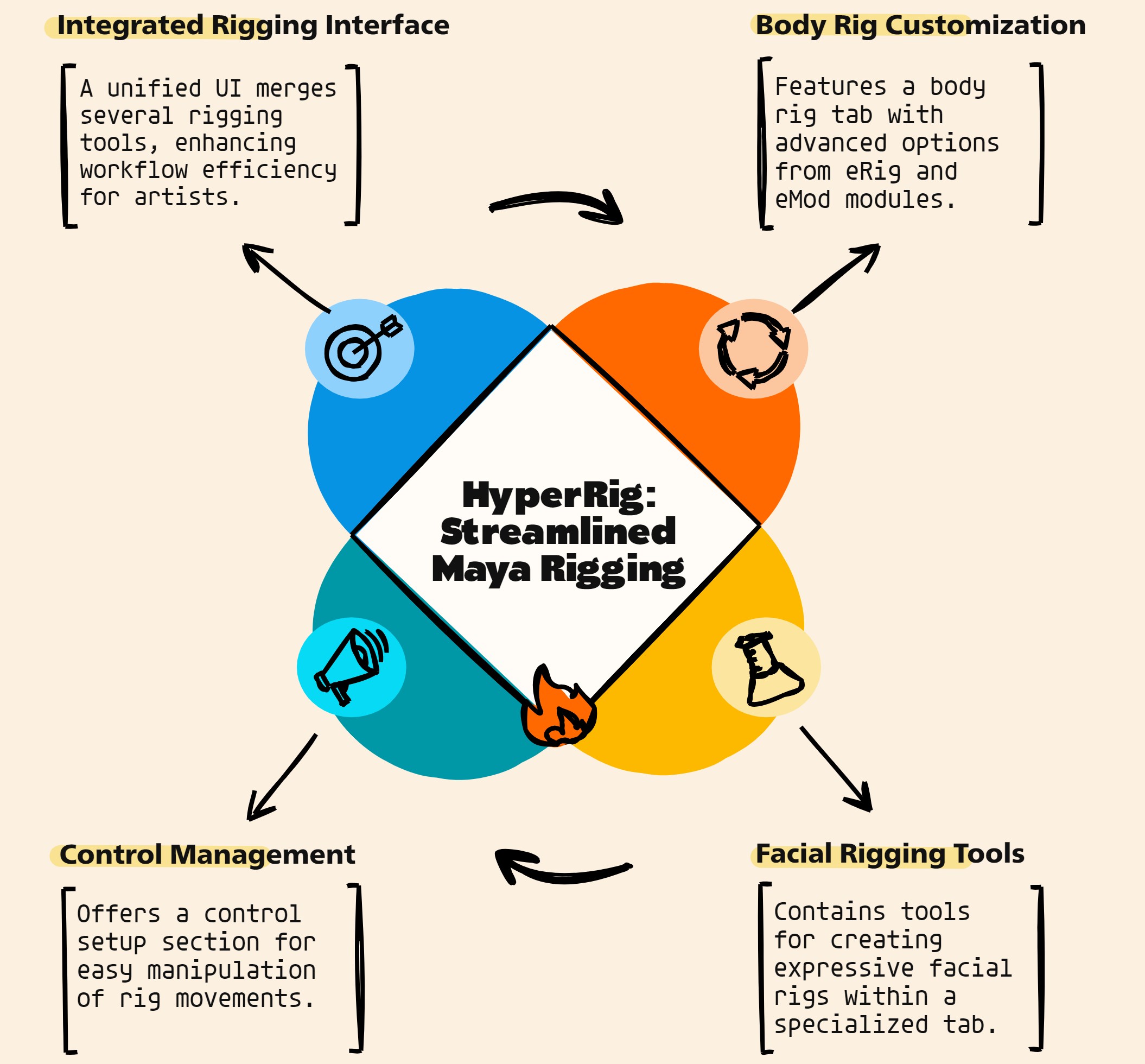
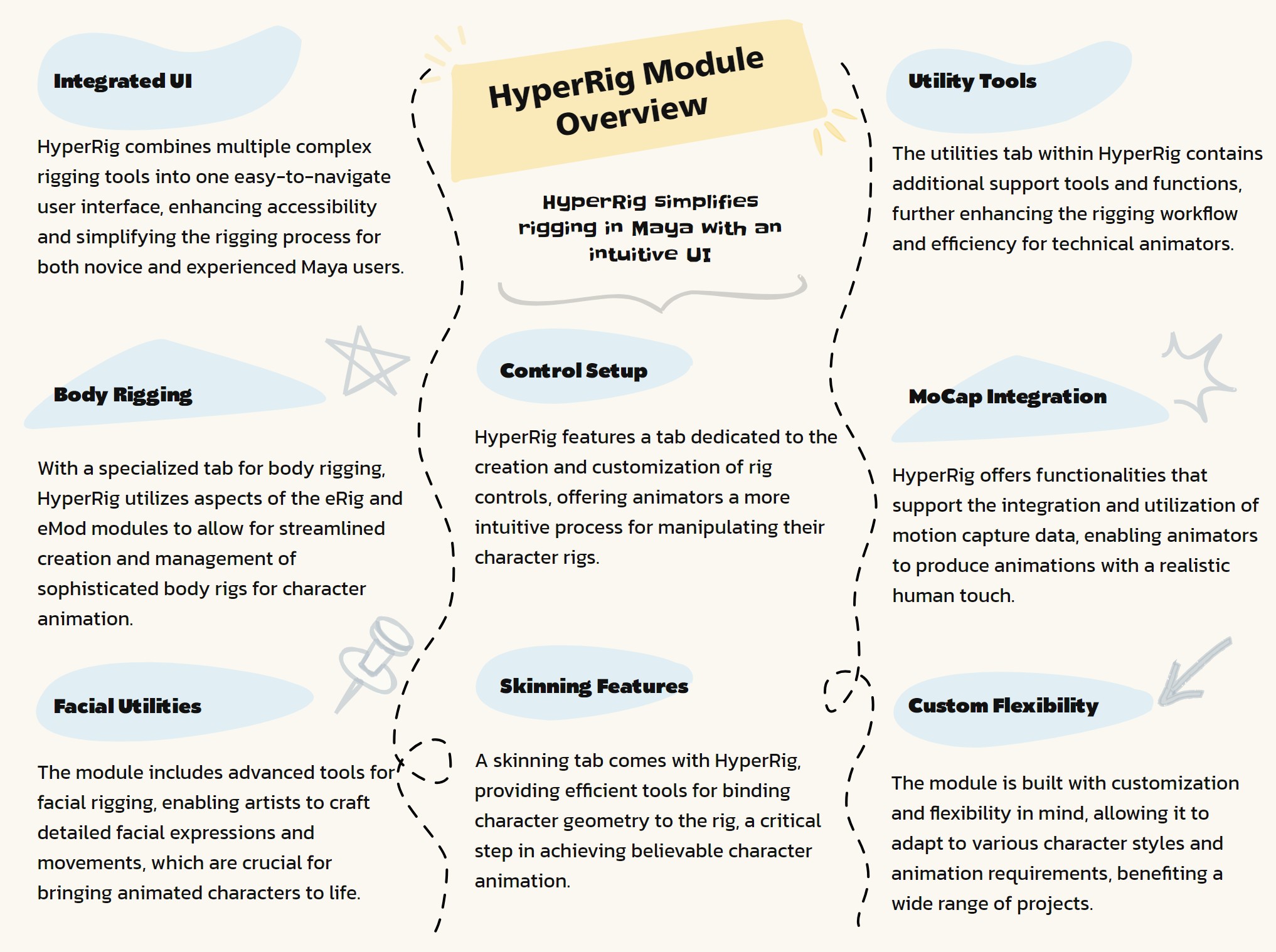
The HyperRig module, designed as a comprehensive rigging tool for Autodesk Maya, encapsulates the functionalities of the previously discussed modules (asNode, eCtrl, eTest, eSpec, eMath, eRig, and eMod) into a user-friendly UI. This approach makes advanced rigging tools accessible to artists, streamlining their workflow. Here are some key features of the HyperRig module:
Integrated UI for Rigging Tools: HyperRig consolidates various rigging tools into a singular, intuitive user interface, making advanced rigging functionalities easily accessible to artists.
Body Rigging Tab: A dedicated tab for body rigging, incorporating tools from modules like eRig and eMod, allows for efficient creation and management of body rigs.
Facial Rigging Utilities: The module includes a specialized tab for facial rigging, offering tools for detailed facial expressions and head movements, essential for character animation.
Control Setup: HyperRig provides a tab for setting up and customizing rig controls, facilitating easy manipulation of character rigs during animation.
Skinning Features: A dedicated skinning tab in the UI helps artists efficiently bind geometry to rigs, crucial for realistic character movement.
Utility Tools: HyperRig includes a utilities tab, which encompasses various support tools and functions for rigging, enhancing overall workflow efficiency.
Motion Capture (MoCap) Integration: The module offers functionalities for integrating and working with motion capture data, essential for animating characters with real-life movements.
Customization and Flexibility: HyperRig allows for customization and flexibility in rigging, catering to the specific needs of different characters and animation styles.
Seamless Workflow Integration: The module is designed to integrate seamlessly with Maya’s environment, ensuring a smooth workflow for rigging and animation tasks.
User-Friendly for Artists: By providing a UI for complex rigging operations, HyperRig makes it more accessible for artists who may not be deeply familiar with scripting or technical aspects of rigging.
HyperRig represents a significant advancement in rigging tools for Maya, offering a comprehensive, user-friendly solution that streamlines the rigging process for artists and technical directors alike.
- HyperRig.__confirmAction(self, action)#
- HyperRig.__init__(self)#
as_Update_BuildBodyModule - For UI options in Body Module as_CreateTemplate - To go to ‘Create Template’ Button Function as_BuildBodyModule - To go to ‘Build Module’ Button Function
- HyperRig._compileHyperRig(self, userFolder='$_Free_asEB')#
import shutil
mayaVer =HyperRig._mayaVer() userPath =’D:/My_Scripts/$_as_HyperRig/$_Scripts_Sold/{}/’.format(userFolder) verPath =userPath + str(mayaVer) if not os.path.exists(verPath):
os.makedirs(verPath)
scriptPath =’D:/My_Scripts/as_Scripts/’ pycFiles =[‘as_HyperRigMain.pyc’, ‘asNode.pyc’, ‘as_eRigMain.pyc’, ‘as_eCtrlMain.pyc’, ‘as_eSpecMain.pyc’, ‘as_eModMain.pyc’, ‘as_eMathMain.pyc’, ‘as_eTestMain.pyc’]
import asNode importlib.reload(asNode) from asNode import *
import as_eRigMain importlib.reload(as_eRigMain) from as_eRigMain import *
import as_eCtrlMain importlib.reload(as_eCtrlMain) from as_eCtrlMain import *
import as_eSpecMain importlib.reload(as_eSpecMain) from as_eSpecMain import *
import as_eTestMain importlib.reload(as_eTestMain) from as_eTestMain import *
import as_eMathMain importlib.reload(as_eMathMain) from as_eMathMain import *
import as_eModMain importlib.reload(as_eModMain) from as_eModMain import *
from as_HyperRigMain import * import as_HyperRigMain importlib.reload(as_HyperRigMain)
from as_HyperRigMain import * import as_HyperRigMain importlib.reload(as_HyperRigMain) #HyperRig.as_HyperRig()
- HyperRig._isInTime(self, startDate=[2017, 1, 1], endDate=[2018, 1, 1], onlineTime=1, showDaysLeft=1, bufferTime=1)#
- HyperRig._mayaVer(self)#
- HyperRig.add_AttrDivider(self, ctrlList=None, **shArgs)#
[shArgs : cl=ctrlList]
Purpose:
:: Adds an attribute divider to organize custom attributes in the channel box of a controller.
Provides a clean and organized way to separate custom attributes from default ones.
Enhances readability and usability of the channel box in complex rigs.
Useful in rigs with a high number of custom attributes.
- Parameters:
ctrlList – <list> # List of controllers to add the attribute divider to.
- Returns:
None # This function does not return a value but modifies the channel box of the specified controllers.
Code Examples:
>>> add_AttrDivider(ctrlList=['ctrl1', 'ctrl2'])
# Adds an attribute divider to the specified controllers.
graph TB Start[("fa:fa-play Start")] --> SelectControllers["/fas:fa-mouse-pointer Select Controllers"] SelectControllers --> CheckCtrlList{"/fas:fa-question-circle Check Ctrl List"} CheckCtrlList --"If Ctrl List Provided"--> AddAttrDivider["/fas:fa-bars Add Attr Divider"] CheckCtrlList --"If No Ctrl List"--> AddAttrDivider AddAttrDivider --> End[("fas:fa-stop End")] style Start fill:#00cc00,stroke:#000,stroke-width:3px style SelectControllers fill:#ffcc00,stroke:#000,stroke-width:2px style CheckCtrlList fill:#ff9999,stroke:#000,stroke-width:2px style AddAttrDivider fill:#99ccff,stroke:#000,stroke-width:2px style End fill:#ff6666,stroke:#000,stroke-width:3px- Flow Chart Description:
This flowchart illustrates the add_AttrDivider function:
The process begins by selecting controllers to which an attribute divider will be added.
- Checks if a list of controllers is provided.
If a controller list is provided, it proceeds to add an attribute divider to each controller in the list.
If no specific controller list is provided, it adds an attribute divider to the currently selected controllers.
Completes the process and ends.
- HyperRig.add_Attrs(self, attr='RotateOrder', onOffSwitch=0, **shArgs)#
[shArgs : a=attr, oos=onOffSwitch]
Purpose:
:: Adds custom attributes to selected controls, such as ‘RotateOrder’ or on/off switches.
Enhances control rig functionality by allowing for custom attribute creation.
Facilitates the animation process by providing additional control over rig components.
Customizable to fit specific rigging and animation needs.
- Parameters:
attr – <str> # The name of the attribute to add. Default is ‘RotateOrder’.
onOffSwitch – <bool> # Whether to add an on/off switch attribute.
- Returns:
None # This function does not return a value but modifies the selected controllers.
Code Examples:
>>> add_Attrs(attr='RotateOrder', onOffSwitch=0)
# Adds a 'RotateOrder' attribute to the selected controllers.
graph TB Start[("fa:fa-play Start")] --> SelectControls["/fas:fa-mouse-pointer Select Controls"] SelectControls --> CheckAttributeType{"/fas:fa-question-circle Check Attribute Type"} CheckAttributeType --"If RotateOrder"--> AddRotateOrderAttr["/fas:fa-sync-alt Add RotateOrder Attribute"] CheckAttributeType --"If OnOff Switch"--> AddOnOffSwitchAttr["/fas:fa-toggle-on Add OnOff Switch Attribute"] AddRotateOrderAttr --> ConnectAttr["/fas:fa-link Connect Attribute"] ConnectAttr --> End[("fas:fa-stop End")] AddOnOffSwitchAttr --> PromptAttrName{"/fas:fa-text-width Prompt Attribute Name"} PromptAttrName --"Input Attribute Name"--> CreateOnOffSwitch["/fas:fa-plus Create OnOff Switch"] PromptAttrName --"Cancel Action"--> CancelAction["/fas:fa-ban Cancel Action"] CreateOnOffSwitch --> End CancelAction --> End style Start fill:#00cc00,stroke:#000,stroke-width:3px style SelectControls fill:#ffcc00,stroke:#000,stroke-width:2px style CheckAttributeType fill:#ff9999,stroke:#000,stroke-width:2px style AddRotateOrderAttr fill:#99ccff,stroke:#000,stroke-width:2px style ConnectAttr fill:#cc99ff,stroke:#000,stroke-width:2px style AddOnOffSwitchAttr fill:#99ff99,stroke:#000,stroke-width:2px style PromptAttrName fill:#ffcc99,stroke:#000,stroke-width:2px style CreateOnOffSwitch fill:#ccffcc,stroke:#000,stroke-width:2px style CancelAction fill:#ff9999,stroke:#000,stroke-width:2px style End fill:#ff6666,stroke:#000,stroke-width:3px- Flow Chart Description:
This flowchart illustrates the add_Attrs function:
Starts by selecting the relevant controls to add attributes to.
- Checks the type of attribute to be added, either ‘RotateOrder’ or an on/off switch.
If ‘RotateOrder’, adds the ‘RotateOrder’ attribute and connects it to the control’s rotate order attribute.
If on/off switch, prompts for the attribute name and creates an on/off switch attribute.
In case of cancellation during on/off switch creation, the action is canceled.
Completes the process and ends.
- HyperRig.add_ClusterToTF(self, textFld, btnName=None, **shArgs)#
[shArgs: tf=textFld, bn=btnName]
Purpose:
:: Adds the name of the selected object with a ‘_ClustCluster’ suffix to a specified text field in Maya UI.
Useful for rigging and animation workflows where cluster names need to be inputted or tracked in the Maya UI.
- Parameters:
textFld – <str> # Name of the text field where the cluster name is to be added.
btnName – <str, optional> # Name of the button associated with the action, used for UI feedback.
- Returns:
None # This function does not return any value but updates the text field with the selected object’s cluster name.
Code Examples:
>>> text_field_name = "clusterNameField"
>>> button_name = "applyClusterButton"
>>> add_ClusterToTF(text_field_name, button_name)
# Adds the cluster name of the selected object to 'clusterNameField'.
graph TB Start[("fa:fa-play Start")] --> CheckSelection{{"/fas:fa-mouse-pointer Check Selection"}} CheckSelection --"Objects Selected"--> GetObjectName[("/fas:fa-tag Get Object Name")] CheckSelection --"No Objects Selected"--> ClearTextField[("/fas:fa-eraser Clear Text Field")] GetObjectName --> UpdateTextField[("/fas:fa-edit Update Text Field")] UpdateTextField --> CheckButton{{"/fas:fa-check-circle Check Button"}} ClearTextField --> CheckButton CheckButton --"Button Exists"--> QueryButton[("/fas:fa-search-plus Query Button State")] QueryButton --> UpdateButton[("/fas:fa-sync-alt Update Button")] CheckButton --"No Button"--> End[("fas:fa-stop-circle End")] UpdateButton --> End style Start fill:#00cc00,stroke:#000,stroke-width:3px style CheckSelection fill:#ffcc00,stroke:#000,stroke-width:2px style GetObjectName fill:#5cb85c,stroke:#000,stroke-width:2px style ClearTextField fill:#d9534f,stroke:#000,stroke-width:2px style UpdateTextField fill:#5bc0de,stroke:#000,stroke-width:2px style CheckButton fill:#f0ad4e,stroke:#000,stroke-width:2px style QueryButton fill:#ff9999,stroke:#000,stroke-width:2px style UpdateButton fill:#99ccff,stroke:#000,stroke-width:2px style End fill:#ff6666,stroke:#000,stroke-width:3px- Flow Chart Description:
This flowchart illustrates the add_ClusterToTF function:
The function begins by checking if any objects are selected in Maya.
If an object is selected, it retrieves the object’s name and updates the specified text field with the object name followed by ‘_ClustCluster’.
If no object is selected, the text field is cleared.
The function then checks if a button name is provided for UI feedback.
If a button is present, its state is queried and updated based on the selection status.
The process ends once the text field and button (if any) are updated.
- HyperRig.add_Prefix(self, txtFldName, btnName=None, **shArgs)#
[shArgs: tfn=txtFldName, bn=btnName]
Purpose:
:: Adds a prefix of the selected object to a specified text field in Maya UI.
Useful for automating naming conventions and ensuring consistency in naming objects within Maya.
- Parameters:
txtFldName – <str> # Name of the text field where the prefix is to be added.
btnName – <str, optional> # Name of the button associated with the action, used for UI feedback.
- Returns:
None # This function does not return any value but updates the text field with the selected object’s prefix.
Code Examples:
>>> text_field_name = "myTextField"
>>> button_name = "myButton"
>>> add_Prefix(text_field_name, button_name)
# Adds the prefix of the selected object to 'myTextField'.
Adds prefix of selected object as Input in any Window for <== button
Usage:
Left_Hand                 # Adds 'Left_' While pressing Enter.. <== button
Hand                    # Adds '' While pressing Enter.. <== button
graph TB Start[("fa:fa-play Start")] --> CheckSelection{"/fas:fa-check-circle Check Selection"} CheckSelection --"If objects are selected"--> ExtractPrefix["/fas:fa-text-width Extract Prefix"] ExtractPrefix --"Get prefix from selected object"--> UpdateTextField["/fas:fa-edit Update Text Field"] CheckSelection --"No objects selected"--> ClearTextField["/fas:fa-eraser Clear Text Field"] ClearTextField --"Set text field to empty"--> UpdateButtonStatus["/fas:fa-sync-alt Update Button Status"] UpdateTextField --"Add prefix to text field"--> UpdateButtonStatus UpdateButtonStatus --"Adjust button appearance based on action"--> End[("fas:fa-stop End")] style Start fill:#00cc00,stroke:#000,stroke-width:3px style CheckSelection fill:#ffcc00,stroke:#000,stroke-width:2px style ExtractPrefix fill:#99ccff,stroke:#000,stroke-width:2px style UpdateTextField fill:#cc99ff,stroke:#000,stroke-width:2px style ClearTextField fill:#ff9999,stroke:#000,stroke-width:2px style UpdateButtonStatus fill:#99ff99,stroke:#000,stroke-width:2px style End fill:#ff6666,stroke:#000,stroke-width:3px- Flow Chart Description:
This flowchart illustrates the add_Prefix function:
The process begins by checking if any objects are selected.
If objects are selected, it extracts the prefix from the selected object.
The prefix is then added to the specified text field.
If no objects are selected, it clears the text field to an empty state.
Finally, the function updates the appearance of the associated button based on the action performed.
- HyperRig.add_Selection(self, textFld, btnName=None, **shArgs)#
[shArgs: tf=textFld, bn=btnName]
Purpose:
:: Adds the name of the selected object to a specified text field in Maya UI.
Ideal for workflows that require quick input of selected object names into Maya’s UI elements.
- Parameters:
textFld – <str> # Name of the text field where the selected object’s name is to be added.
btnName – <str, optional> # Name of the button associated with the action, used for UI feedback.
- Returns:
None # This function does not return any value but updates the text field with the selected object’s name.
Code Examples:
>>> text_field_name = "objectNameField"
>>> button_name = "addButton"
>>> add_Selection(text_field_name, button_name)
# Adds the name of the selected object to 'objectNameField'.
Adds selected object’s name as Input in any Window for <== button
Usage:
obj10             # Adds 'obj10' While pressing Enter.. <== button
box25           # Adds 'box25' While pressing Enter.. <== button
graph TB Start[("fa:fa-play Start")] --> CheckSelection{"/fas:fa-check-circle Check Selection"} CheckSelection --"If objects are selected"--> ExtractName["/fas:fa-text-width Extract Name"] ExtractName --"Get name from selected object"--> UpdateTextField["/fas:fa-edit Update Text Field"] CheckSelection --"No objects selected"--> ClearTextField["/fas:fa-eraser Clear Text Field"] ClearTextField --"Set text field to empty"--> UpdateButtonStatus["/fas:fa-sync-alt Update Button Status"] UpdateTextField --"Add object name to text field"--> UpdateButtonStatus UpdateButtonStatus --"Adjust button appearance based on action"--> End[("fas:fa-stop End")] style Start fill:#00cc00,stroke:#000,stroke-width:3px style CheckSelection fill:#ffcc00,stroke:#000,stroke-width:2px style ExtractName fill:#99ccff,stroke:#000,stroke-width:2px style UpdateTextField fill:#cc99ff,stroke:#000,stroke-width:2px style ClearTextField fill:#ff9999,stroke:#000,stroke-width:2px style UpdateButtonStatus fill:#99ff99,stroke:#000,stroke-width:2px style End fill:#ff6666,stroke:#000,stroke-width:3px- Flow Chart Description:
This flowchart illustrates the add_Selection function:
The process begins by checking if any objects are selected.
If objects are selected, it extracts the name from the selected object.
The object name is then added to the specified text field.
If no objects are selected, it clears the text field to an empty state.
Finally, the function updates the appearance of the associated button based on the action performed.
- HyperRig.add_ToesTemplate(self, **shArgs)#
[shArgs : ]
Purpose:
:: Adds toe templates to a foot rig in Autodesk Maya.
This function creates additional toe templates based on the given foot name prefix.
It duplicates and positions toe curves to create a series of toe templates.
- Parameters:
toesPrefix – <str> #Prefix for the foot name to which toes templates are added.
- Returns:
None #No return value, it adds toe templates to the existing foot rig.
Code Examples:
>>> toesPrefix = 'Foot'
>>> add_ToesTemplate()
graph TB Start[("fa:fa-play Start")] --> GetToesPrefix["/fas:fa-tag Get Toes Prefix"] GetToesPrefix --> CheckDigitCurveExists{{"/fas:fa-question-circle Check if Digit Curve Exists"}} CheckDigitCurveExists --"If Exists"--> DuplicateLastCurve["/fas:fa-clone Duplicate Last Curve"] CheckDigitCurveExists --"If Not Exists"--> DuplicatePinkyCurve["/fas:fa-clone Duplicate Pinky Curve"] DuplicateLastCurve --> RenameDuplicateCurve["/fas:fa-i-cursor Rename Duplicate Curve"] DuplicatePinkyCurve --> RenameDuplicateCurve RenameDuplicateCurve --> PositionCurve["/fas:fa-arrows-alt Position Curve"] PositionCurve --> BasicSetup["/fas:fa-tools Basic Setup"] BasicSetup --> End[("fas:fa-stop End")] style Start fill:#00cc00,stroke:#000,stroke-width:3px style GetToesPrefix fill:#ffcc00,stroke:#000,stroke-width:2px style CheckDigitCurveExists fill:#99ff99,stroke:#000,stroke-width:2px style DuplicateLastCurve fill:#ff9999,stroke:#000,stroke-width:2px style DuplicatePinkyCurve fill:#99ccff,stroke:#000,stroke-width:2px style RenameDuplicateCurve fill:#cc99ff,stroke:#000,stroke-width:2px style PositionCurve fill:#ffcc99,stroke:#000,stroke-width:2px style BasicSetup fill:#ccffcc,stroke:#000,stroke-width:2px style End fill:#ff6666,stroke:#000,stroke-width:3px- Flow Chart Description:
This flowchart illustrates the add_ToesTemplate function:
The function begins by retrieving the toes prefix from the user input.
It then checks if the digit curve for the toe already exists in the scene.
If the digit curve exists, it duplicates the last curve in the series; otherwise, it duplicates the pinky curve.
The duplicated curve is then renamed appropriately.
Positions the newly created curve relative to the last toe or the pinky toe.
Performs a basic setup for the new toe curve using the eMod class.
Completes the process by adding the new toe template to the existing foot rig.
- HyperRig.advSkel_mirrorOrientCtrlGrps(self, **shArgs)#
[shArgs : ]
Purpose:
:: Mirrors orientation and control groups of a selected skeletal structure to the opposite side.
Aids in symmetrically rigging characters by automating the mirroring of control groups.
Ensures consistent orientation and setup between corresponding parts of a character.
Streamlines the rigging process for complex characters with symmetrical features.
- Returns:
None # This function does not return a value but mirrors the orientation and control groups.
Code Examples:
>>> advSkel_mirrorOrientCtrlGrps()
# Mirrors the orientation and control groups of selected controllers to the opposite side.
graph TB Start[("fa:fa-play Start")] --> SelectControllers["/fas:fa-mouse-pointer Select Controllers"] SelectControllers --> MirrorOrientationGroups["/fas:fa-exchange-alt Mirror Orientation Groups"] MirrorOrientationGroups --> IterateControllers{"/fas:fa-repeat Iterate Controllers"} IterateControllers --"For Each Controller"--> GetControlGroup["/fas:fa-object-group Get Control Group"] GetControlGroup --> GetMirrorGroup["/fas:fa-object-ungroup Get Mirror Group"] GetMirrorGroup --> SetRotationAttributes["/fas:fa-sync-alt Set Rotation Attributes"] SetRotationAttributes --> ReparentJoint["/fas:fa-link Reparent Joint"] ReparentJoint --> AddMirrorController["/fas:fa-user-circle Add Mirror Controller"] AddMirrorController --> End[("fas:fa-stop End")] style Start fill:#00cc00,stroke:#000,stroke-width:3px style SelectControllers fill:#ffcc00,stroke:#000,stroke-width:2px style MirrorOrientationGroups fill:#ff9999,stroke:#000,stroke-width:2px style IterateControllers fill:#99ccff,stroke:#000,stroke-width:2px style GetControlGroup fill:#cc99ff,stroke:#000,stroke-width:2px style GetMirrorGroup fill:#99ff99,stroke:#000,stroke-width:2px style SetRotationAttributes fill:#ffcc99,stroke:#000,stroke-width:2px style ReparentJoint fill:#ccffcc,stroke:#000,stroke-width:2px style AddMirrorController fill:#99ccff,stroke:#000,stroke-width:2px style End fill:#ff6666,stroke:#000,stroke-width:3px- Flow Chart Description:
This flowchart illustrates the advSkel_mirrorOrientCtrlGrps function:
The process begins by selecting controllers whose orientation and control groups need to be mirrored.
Mirrors the orientation groups of the selected controllers.
- Iterates through each selected controller to handle mirroring individually.
Retrieves the control group of the current controller.
Identifies and sets up the corresponding mirror group.
Sets the rotation attributes for the mirror group.
Reparents the joint to the mirrored controller.
Adds the mirrored controller to the list for selection.
Completes the process by selecting the mirrored controllers and ends.
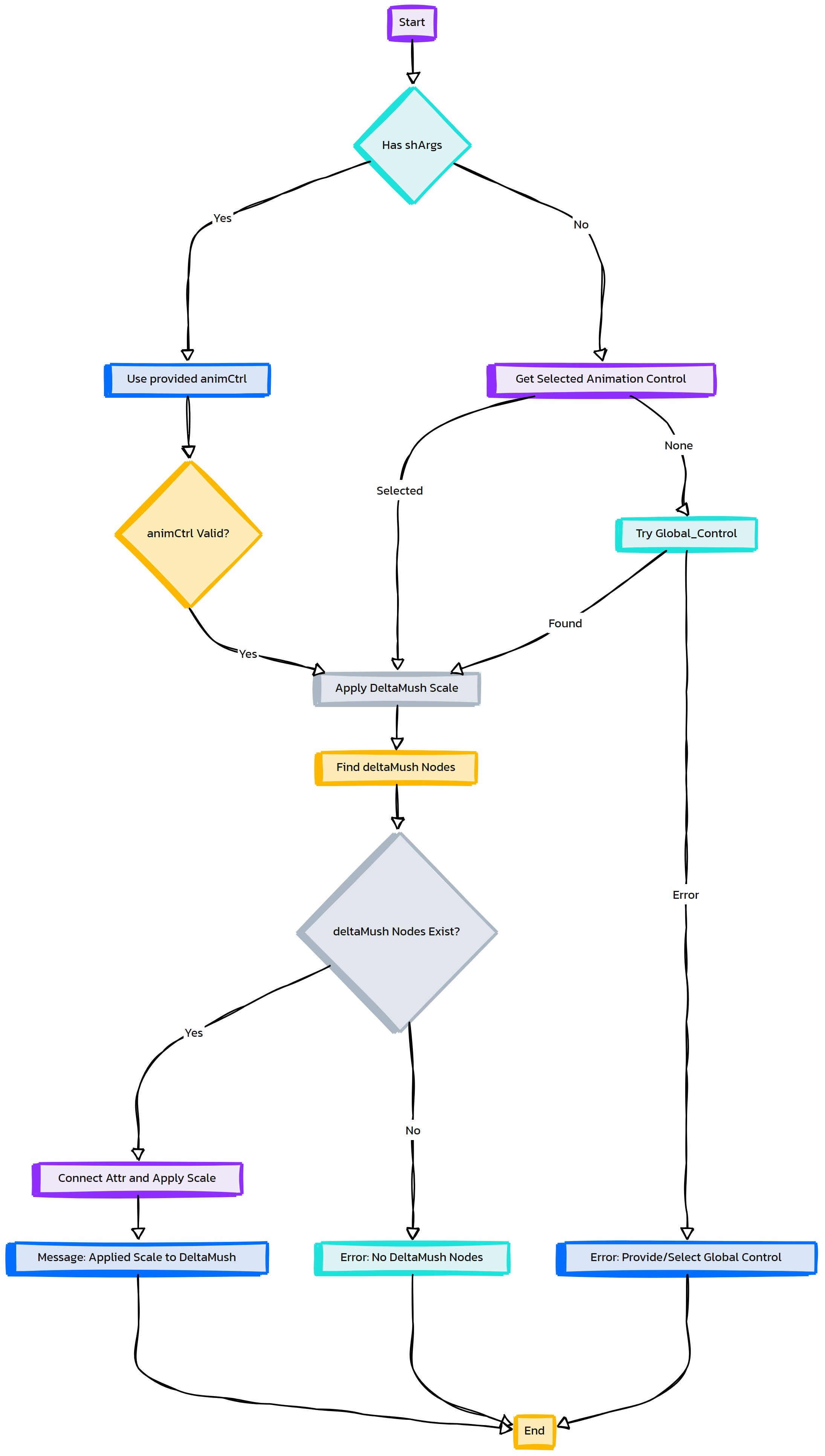
- HyperRig.applyDeltaMushScale(self, animCtrl=None, **shArgs)#
[shArgs: ac=animCtrl]
Purpose:
:: Applies global scale to all ‘deltaMush’ nodes in a Maya scene, using a specified animation control.
This function is particularly useful in rigging workflows to maintain consistency in deformation effects when scaling characters or assets.
- Parameters:
animCtrl – <str/PyNode, optional> # The animation control used to apply the global scale. If not provided, it will default to the selected control or ‘Global_Control’.
- Returns:
None # This function does not return any value but applies global scale to all ‘deltaMush’ nodes.
Code Examples:
>>> animation_control = "characterGlobalCtrl"
>>> applyDeltaMushScale(animation_control)
# Applies global scale to all 'deltaMush' nodes using 'characterGlobalCtrl'.
- HyperRig.as_AboutHyperRig(self, **shArgs)#
[shArgs: ]
Purpose:
:: Displays information about the as_HyperRig tool, including credits, contact details, and version.
This function provides a UI window that showcases the author’s information and additional resources related to as_HyperRig.
- Returns:
None # This function does not return any value but displays a UI window with as_HyperRig information.
Code Examples:
>>> as_AboutHyperRig()
# Opens a window displaying information about as_HyperRig.
graph TB Start[("fa:fa-play Start")] --> CheckExistingWindow{{"/fas:fa-window-close Check Existing Window"}} CheckExistingWindow --"If window exists"--> DeleteWindow["/fas:fa-trash-alt Delete Window"] DeleteWindow --"Window deleted"--> CreateWindow["/fas:fa-window-maximize Create New Window"] CheckExistingWindow --"If window does not exist"--> CreateWindow CreateWindow --"Initialize about window"--> AddContent["/fas:fa-text-height Add Content"] AddContent --"Display HyperRig information"--> ShowWindow["/fas:fa-eye Show Window"] ShowWindow --"Present window to user"--> WaitForClose[("/fas:fa-clock Wait for Close")] WaitForClose --"Close window after delay"--> End[("fas:fa-stop End")] style Start fill:#00cc00,stroke:#000,stroke-width:3px style CheckExistingWindow fill:#ffcc00,stroke:#000,stroke-width:2px style DeleteWindow fill:#99ccff,stroke:#000,stroke-width:2px style CreateWindow fill:#cc99ff,stroke:#000,stroke-width:2px style AddContent fill:#ff9999,stroke:#000,stroke-width:2px style ShowWindow fill:#99ff99,stroke:#000,stroke-width:2px style WaitForClose fill:#ffcc00,stroke:#000,stroke-width:2px style End fill:#ff6666,stroke:#000,stroke-width:3px- Flow Chart Description:
This flowchart illustrates the as_AboutHyperRig function:
The process starts by checking if the HyperRig information window already exists.
If it exists, the existing window is deleted.
A new window is created to display the HyperRig information.
Relevant HyperRig information and credits are added to the window.
The window is then displayed to the user.
After a brief pause, the window is automatically closed.
- HyperRig.as_ApplyCBS_cvShapeInv(self, rAttr='ry', selectedAttr=False, **shArgs)#
[shArgs : ]
Purpose:
:: Applies corrective blend shapes (CBS) using curve shape inversion in Autodesk Maya, primarily used in advanced character rigging.
This function is utilized to apply corrective blend shapes to a skinned mesh based on various transformation attributes of controllers or joints.
It handles different object types like joints, locators, and plusMinusAverage nodes to determine the pose for applying the corrective shape.
The function supports selective attribute application, where users can choose specific attributes from a channel box for corrective action.
It includes options to manage group names, pose mesh names, and blend shape node names for precise control over the corrective process.
The setup is adaptable, allowing for the integration of corrective blend shapes into complex rigging systems.
- Returns:
None # This function configures corrective blend shapes but doesn’t return a value.
Code Examples:
>>> as_ApplyCBS_cvShapeInv(rAttr='ry', selectedAttr=False)
# Applies corrective blend shapes based on rotation or transformation attributes of a rig component.
graph TB Start[("fa:fa-play Start")] --> CheckObjects{"/fas:fa-check-circle Check Objects"} CheckObjects --"Check for skin mesh, pose control, joints, etc."--> InitializeVariables["/fas:fa-sliders-h Initialize Variables"] InitializeVariables --"Set initial variables and filter lists"--> DetermineCBSName{{"/fas:fa-question-circle Determine CBS Name"}} DetermineCBSName --"Check if CBS name exists"--> CheckPoseMesh["/fas:fa-search Check Pose Mesh"] DetermineCBSName --"If CBS name doesn't exist"--> CreateCBSName["/fas:fa-plus Create CBS Name"] CreateCBSName --> CheckPoseMesh CheckPoseMesh --"Check and prepare pose mesh"--> ApplyCBS{"/fas:fa-magic Apply CBS"} ApplyCBS --"Apply corrective blend shapes"--> End[("fas:fa-stop End")] style Start fill:#00cc00,stroke:#000,stroke-width:3px style CheckObjects fill:#ffcc00,stroke:#000,stroke-width:2px style InitializeVariables fill:#99ccff,stroke:#000,stroke-width:2px style DetermineCBSName fill:#ffcc00,stroke:#000,stroke-width:2px style CheckPoseMesh fill:#99ccff,stroke:#000,stroke-width:2px style CreateCBSName fill:#cc99ff,stroke:#000,stroke-width:2px style ApplyCBS fill:#cc99ff,stroke:#000,stroke-width:2px style End fill:#ff6666,stroke:#000,stroke-width:3px- Flow Chart Description:
This flowchart illustrates the as_ApplyCBS_cvShapeInv function:
The function starts by checking for the necessary objects like skin mesh, pose control, and joints.
It initializes variables and filters lists based on selected objects.
The process then determines if a corrective blend shape (CBS) name exists, or creates one if it doesn’t.
It checks and prepares the pose mesh for applying corrective blend shapes.
The function applies corrective blend shapes based on various transformation attributes of controllers or joints.
The process concludes after applying the corrective blend shapes.
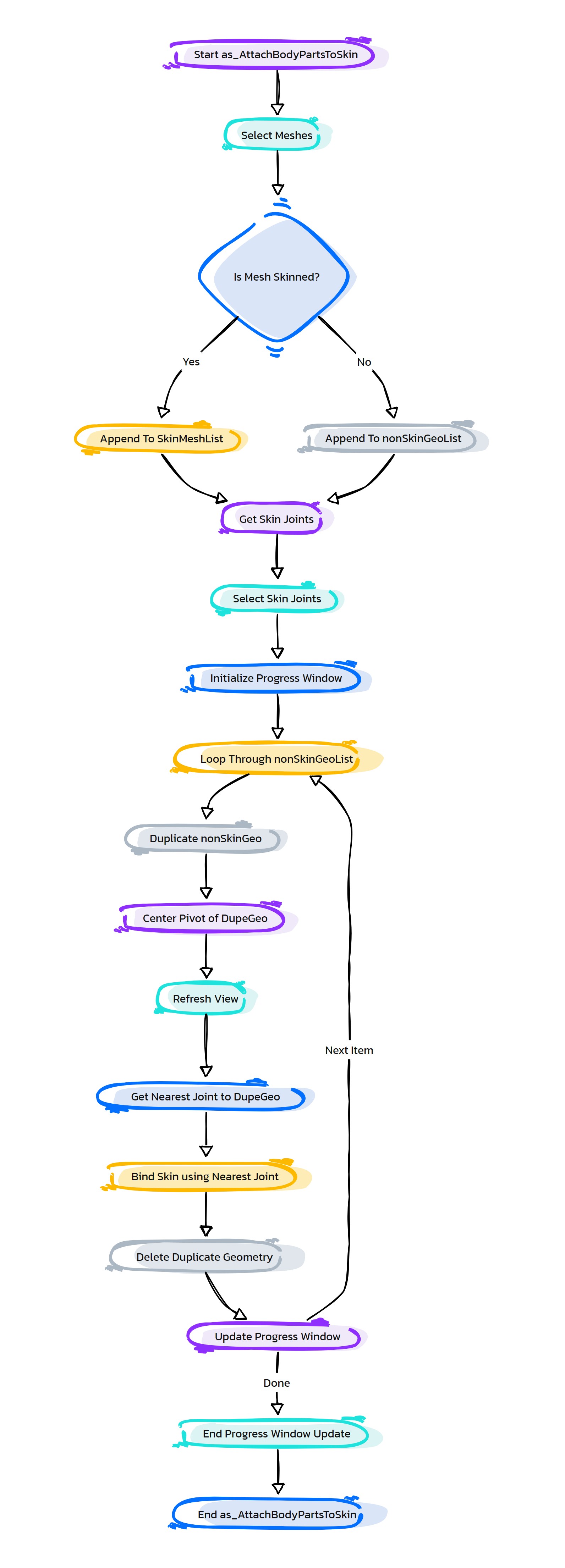
- HyperRig.as_AttachBodyPartsToSkin(self, **shArgs)#
[shArgs : ]
Purpose:
:: Attaches non-skinned geometry, like nails or accessories, to skinned meshes, ensuring they move correctly with the character’s animation.
This function is designed for attaching non-skinned geometries like accessories or clothes to already skinned character meshes.
It ensures that these additional geometries deform correctly in sync with the underlying skinned mesh.
The function automatically detects and binds the closest joints to the non-skinned geometry for accurate skinning.
It is particularly useful in complex character setups where additional geometries need to be added post the initial skinning process.
The setup enhances the rig’s functionality by allowing additional elements to be included without compromising the rig’s integrity.
- Returns:
None # This function performs skinning of additional geometries but doesn’t return a value.
Code Examples:
>>> as_AttachBodyPartsToSkin()
# Attaches non-skinned geometries like nails or clothes to skinned character meshes in Autodesk Maya.
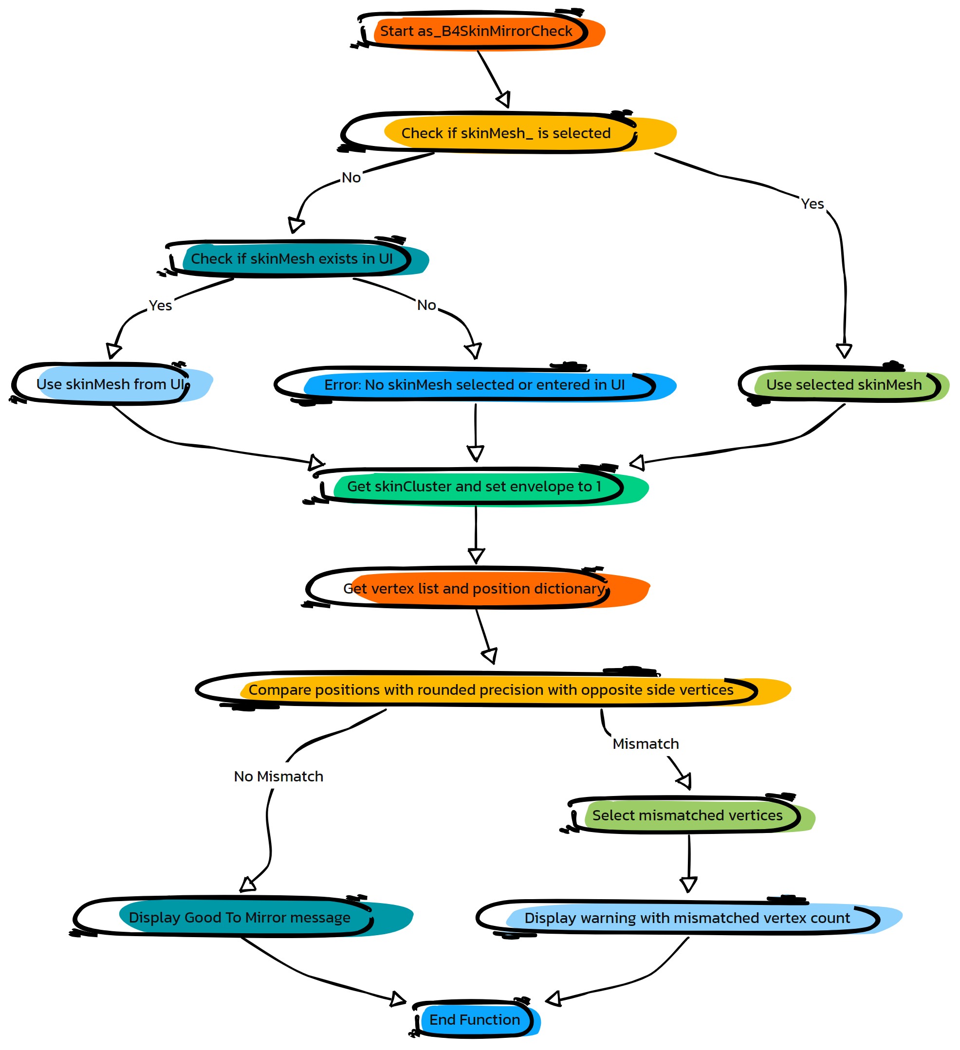
- HyperRig.as_B4SkinMirrorCheck(self, precision=5, **shArgs)#
[shArgs: ]
Purpose:
:: Performs a pre-mirroring check on skin weights for a selected mesh in Autodesk Maya.
Similar to as_B4SkinMirrorCheck02, this function ensures that skin weights are properly set up before performing a skin weight mirroring operation.
- Parameters:
precision – <int> # The precision level for comparing vertex positions.
- Returns:
None # This function does not return any value but performs a check on the skin weights of the selected mesh.
Code Examples:
>>> precision_level = 5
>>> as_B4SkinMirrorCheck(precision_level)
# Performs a pre-mirroring check on skin weights with specified precision.
- HyperRig.as_B4SkinMirrorCheck02(self, precision=4, manageJunk=1, **shArgs)#
[shArgs: ]
Purpose:
:: Performs a pre-mirroring check on skin weights for a selected mesh in Autodesk Maya.
This function is designed to ensure that skin weights are in a proper state before performing a skin weight mirroring operation.
- Parameters:
precision – <int> # The precision level for comparing vertex positions.
manageJunk – <bool> # Determines if additional cleanup or management actions should be performed.
- Returns:
None # This function does not return any value but performs a check on the skin weights of the selected mesh.
Code Examples:
>>> precision_level = 4
>>> manage_junk = True
>>> as_B4SkinMirrorCheck02(precision_level, manage_junk)
# Performs a pre-mirroring check on skin weights with specified precision and management actions.
graph TB Start[("fa:fa-play Start")] --> CheckSelection[("/fas:fa-check-circle Check Selection")] CheckSelection --"Verify selection of mesh" --> GetSkinCluster[("/fas:fa-sitemap Get Skin Cluster")] GetSkinCluster --"Retrieve associated skin cluster" --> EnableSkinDeformer[("/fas:fa-toggle-on Enable Skin Deformer")] EnableSkinDeformer --"Activate skin deformer" --> IterateVerticesOn[("/fas:fa-forward Iterate Vertices with Skin On")] IterateVerticesOn --"Iterate through vertices, store positions" --> DisableSkinDeformer[("/fas:fa-toggle-off Disable Skin Deformer")] DisableSkinDeformer --"Deactivate skin deformer" --> IterateVerticesOff[("/fas:fa-backward Iterate Vertices with Skin Off")] IterateVerticesOff --"Iterate through vertices, compare positions" --> CheckMismatch[("/fas:fa-exclamation-triangle Check for Mismatch")] CheckMismatch --"Identify vertices not at bind pose" --> DisplayResult[("/fas:fa-info Display Result")] DisplayResult --"Show result of check" --> End[("fas:fa-stop-circle End")] style Start fill:#00cc00,stroke:#000,stroke-width:3px style CheckSelection fill:#ffcc00,stroke:#000,stroke-width:2px style GetSkinCluster fill:#5bc0de,stroke:#000,stroke-width:2px style EnableSkinDeformer fill:#f0ad4e,stroke:#000,stroke-width:2px style IterateVerticesOn fill:#5cb85c,stroke:#000,stroke-width:2px style DisableSkinDeformer fill:#d9534f,stroke:#000,stroke-width:2px style IterateVerticesOff fill:#337ab7,stroke:#000,stroke-width:2px style CheckMismatch fill:#f7e1b5,stroke:#000,stroke-width:2px style DisplayResult fill:#5cb85c,stroke:#000,stroke-width:2px style End fill:#ff6666,stroke:#000,stroke-width:3px- Flow Chart Description:
This flowchart illustrates the as_B4SkinMirrorCheck02 function:
The process begins by verifying if a mesh is selected.
It retrieves the associated skin cluster of the selected mesh.
The skin deformer is activated to maintain skin influences.
The function iterates through all mesh vertices with the skin deformer on, storing their positions.
The skin deformer is then deactivated for subsequent operations.
It iterates through the vertices again with the skin deformer off, comparing their positions.
Any mismatch in vertex positions, indicating vertices not at the bind pose, are identified.
The result of the check is displayed, showing whether the mesh is ready for skin weight mirroring.
The process concludes after displaying the result.
- HyperRig.as_BakeDeformers_ToSkinClust(self, skinGeo=None, fastMethod=True, **shArgs)#
[shArgs: ]
Purpose:
:: Bakes deformers into a skin cluster, optimizing rig performance and reducing computation overhead.
Ideal for complex rigs where multiple deformers are used and performance optimization is crucial.
Follows a specific set of guidelines and settings to ensure smooth weight distribution and performance improvement.
- Parameters:
skinGeo – <str, optional> #The name of the skin geometry to which deformers are to be baked.
fastMethod – <bool, optional> #Determines whether to use a faster method for baking. Default is True.
- Returns:
None # This function does not return any value but bakes deformers into the skin cluster of the specified geometry.
Code Examples:
>>> as_BakeDeformers_ToSkinClust('character_mesh', True)
# Bakes deformers into the skin cluster of 'character_mesh' using the fast method.
Usage:
1. Make sure max influences per vertex are set in advance so that after baking, weights distribution happens smoothly
2. Remove unused influences, Export Weights, Rebind and Import Weights (Performance imp: 30 Min to 30 Secs)
3. Mesh should be at bind pose before Baking starts
4. After baking without errors, if weights transfer is bad, lookout for non-unique names of skinned joints
5. Bind Settings:
        *Selected Joints
        *Closest in Hierarchy
        *Weight Blended
        *Interactive
        *Neighbours
        *Allow Multiple Bind Poses - OFF
        *Max Influences - 10
        *Maintain Max Influences - OFF
        *Colorise Skeleton - OFF
        *Remove Unused Infs - OFF
        *Include Hidden Selection - OFF
        *Drop Off Rate - 8.5
graph TB Start[("fa:fa-play Start")] --> CheckSelection{"/fas:fa-check-circle Check Selection"} CheckSelection --"If skin geometry is selected"--> GetSkinCluster{"/fas:fa-search-plus Get Skin Cluster"} CheckSelection --"If no skin geometry selected"--> End[("fas:fa-stop End")] GetSkinCluster --"Get skin cluster from selected geometry"--> CheckUniqueNames CheckUniqueNames{"/fas:fa-question-circle Check Unique Names"} --"If non-unique joint names found"--> DisplayError1{"/fas:fa-exclamation-triangle Display Error"} DisplayError1 --> End CheckUniqueNames --"If all joint names are unique"--> DuplicateJoints{"/fas:fa-clone Duplicate Joints"} DuplicateJoints --"Create duplicate joints for each skinned joint"--> AddToSkinCluster{"/fas:fa-plus-circle Add To Skin Cluster"} AddToSkinCluster --"Add duplicated joints to skin cluster"--> StartBaking StartBaking["/fas:fa-cookie-bite Start Baking Process"] --"Begin baking process"--> AnalyzeWeights{"/fas:fa-balance-scale Analyze Weights"} AnalyzeWeights --"Analyze weights for each joint"--> ReApplyWeights{"/fas:fa-sync Re-Apply Weights"} ReApplyWeights --"Re-apply weights from duplicated joints to original joints"--> RemoveDuplicates{"/fas:fa-trash-alt Remove Duplicates"} RemoveDuplicates --"Remove duplicated joints"--> CleanUp{"/fas:fa-broom Clean Up"} CleanUp --"Perform clean up tasks"--> End style Start fill:#00cc00,stroke:#000,stroke-width:3px style CheckSelection fill:#f0ad4e,stroke:#000,stroke-width:2px style GetSkinCluster fill:#5bc0de,stroke:#000,stroke-width:2px style CheckUniqueNames fill:#f0ad4e,stroke:#000,stroke-width:2px style DisplayError1 fill:#d9534f,stroke:#000,stroke-width:2px style DuplicateJoints fill:#5bc0de,stroke:#000,stroke-width:2px style AddToSkinCluster fill:#5bc0de,stroke:#000,stroke-width:2px style StartBaking fill:#f0ad4e,stroke:#000,stroke-width:2px style AnalyzeWeights fill:#5bc0de,stroke:#000,stroke-width:2px style ReApplyWeights fill:#5bc0de,stroke:#000,stroke-width:2px style RemoveDuplicates fill:#5bc0de,stroke:#000,stroke-width:2px style CleanUp fill:#5cb85c,stroke:#000,stroke-width:2px style End fill:#ff6666,stroke:#000,stroke-width:3px- Flow Chart Description:
This flowchart illustrates the as_BakeDeformers_ToSkinClust function:
The process begins by checking if the skin geometry is selected. If no skin geometry is selected, the function ends.
It retrieves the skin cluster from the selected geometry.
The function checks for unique joint names. If non-unique names are found, an error is displayed and the process ends.
If all joint names are unique, the function duplicates each skinned joint.
The duplicated joints are added to the skin cluster.
The baking process starts, analyzing weights for each joint.
Weights are re-applied from duplicated joints to the original joints.
Duplicated joints are removed after the baking process.
The function performs clean-up tasks and concludes.
- HyperRig.as_BakeLattice_ToSkinClust(self, skinGeo=None, **shArgs)#
[shArgs: ]
Purpose:
:: Converts lattice deformations to skin cluster weights, streamlining the rig and enhancing performance.
Useful in situations where lattice deformers are initially used for shaping but need to be converted to skin clusters for animation.
The function targets the specified or selected skin geometry for the conversion.
- Parameters:
skinGeo – <str, optional> #The name of the skin geometry to which lattice deformations are to be baked.
- Returns:
None # This function does not return any value but converts lattice deformations to skin cluster weights on the specified geometry.
Code Examples:
>>> as_BakeLattice_ToSkinClust('character_mesh')
# Converts lattice deformations to skin cluster weights on 'character_mesh'.
graph TB Start[("fa:fa-play Start")] --> CheckSelection{"/fas:fa-check-circle Check Selection"} CheckSelection --"If skin geometry is selected"--> GetLatticeDeformer{"/fas:fa-search-plus Get Lattice Deformer"} CheckSelection --"If no skin geometry selected"--> End[("fas:fa-stop End")] GetLatticeDeformer --"Get lattice deformer from selected geometry"--> CheckLattice CheckLattice{"/fas:fa-question-circle Check Lattice"} --"If no lattice deformer found"--> DisplayError1{"/fas:fa-exclamation-triangle Display Error"} DisplayError1 --> End CheckLattice --"If lattice deformer found"--> DuplicateJoints{"/fas:fa-clone Duplicate Joints"} DuplicateJoints --"Create duplicate joints for each skinned joint"--> AddToSkinCluster{"/fas:fa-plus-circle Add To Skin Cluster"} AddToSkinCluster --"Add duplicated joints to skin cluster"--> StartBaking StartBaking["/fas:fa-cookie-bite Start Baking Process"] --"Begin baking process"--> AnalyzeWeights{"/fas:fa-balance-scale Analyze Weights"} AnalyzeWeights --"Analyze weights for each joint"--> ReApplyWeights{"/fas:fa-sync Re-Apply Weights"} ReApplyWeights --"Re-apply weights from duplicated joints to original joints"--> RemoveDuplicates{"/fas:fa-trash-alt Remove Duplicates"} RemoveDuplicates --"Remove duplicated joints"--> CleanUp{"/fas:fa-broom Clean Up"} CleanUp --"Perform clean up tasks"--> End style Start fill:#00cc00,stroke:#000,stroke-width:3px style CheckSelection fill:#f0ad4e,stroke:#000,stroke-width:2px style GetLatticeDeformer fill:#5bc0de,stroke:#000,stroke-width:2px style CheckLattice fill:#f0ad4e,stroke:#000,stroke-width:2px style DisplayError1 fill:#d9534f,stroke:#000,stroke-width:2px style DuplicateJoints fill:#5bc0de,stroke:#000,stroke-width:2px style AddToSkinCluster fill:#5bc0de,stroke:#000,stroke-width:2px style StartBaking fill:#f0ad4e,stroke:#000,stroke-width:2px style AnalyzeWeights fill:#5bc0de,stroke:#000,stroke-width:2px style ReApplyWeights fill:#5bc0de,stroke:#000,stroke-width:2px style RemoveDuplicates fill:#5bc0de,stroke:#000,stroke-width:2px style CleanUp fill:#5cb85c,stroke:#000,stroke-width:2px style End fill:#ff6666,stroke:#000,stroke-width:3px- Flow Chart Description:
This flowchart illustrates the as_BakeLattice_ToSkinClust function:
The process begins by checking if the skin geometry is selected. If no skin geometry is selected, the function ends.
It retrieves the lattice deformer from the selected geometry.
The function checks for the presence of a lattice deformer. If no lattice deformer is found, an error is displayed and the process ends.
If a lattice deformer is found, the function duplicates each skinned joint.
The duplicated joints are added to the skin cluster.
The baking process starts, analyzing weights for each joint.
Weights are re-applied from duplicated joints to the original joints.
Duplicated joints are removed after the baking process.
The function performs clean-up tasks and concludes.
- HyperRig.as_BendySetupBiped_Hands(self, **shArgs)#
[shArgs : ]
Purpose:
:: Sets up a bendy rig for the hands of a biped character, enhancing the naturalism and flexibility of hand animations.
Essential for detailed hand movements and gestures in bipedal character animation.
Bendy controls provide smooth deformation for fingers and palms, contributing to more lifelike and expressive hand motions.
Adaptable to various biped characters with different hand rigging needs.
- Returns:
None # This function does not return a value but sets up a bendy rig for the hands of a biped character.
Code Examples:
>>> as_BendySetupBiped_Hands()
# Sets up a bendy rig for the hands of a biped character.
graph TB Start[("fa:fa-play Start")] --> InitializeSetup["/fas:fa-cogs Initialize Bendy Setup"] InitializeSetup --> SetupLeftElbowBendy["/fas:fa-sitemap Setup Left Elbow Bendy"] SetupLeftElbowBendy --> SetupLeftShoulderBendy["/fas:fa-sitemap Setup Left Shoulder Bendy"] SetupLeftShoulderBendy --> SetupRightElbowBendy["/fas:fa-sitemap Setup Right Elbow Bendy"] SetupRightElbowBendy --> SetupRightShoulderBendy["/fas:fa-sitemap Setup Right Shoulder Bendy"] SetupRightShoulderBendy --> FinalizeSetup["/fas:fa-check Finalize Bendy Setup"] FinalizeSetup --> End[("fas:fa-stop End")] style Start fill:#00cc00,stroke:#000,stroke-width:3px style InitializeSetup fill:#ffcc00,stroke:#000,stroke-width:2px style SetupLeftElbowBendy fill:#ff9999,stroke:#000,stroke-width:2px style SetupLeftShoulderBendy fill:#99ccff,stroke:#000,stroke-width:2px style SetupRightElbowBendy fill:#cc99ff,stroke:#000,stroke-width:2px style SetupRightShoulderBendy fill:#99ff99,stroke:#000,stroke-width:2px style FinalizeSetup fill:#99ccff,stroke:#000,stroke-width:2px style End fill:#ff6666,stroke:#000,stroke-width:3px- Flow Chart Description:
This flowchart illustrates the as_BendySetupBiped_Hands function:
The process begins with initializing the bendy setup for biped hands.
Implements bendy controls for the left elbow, designed for enhanced hand animation.
Sets up bendy controls for the left shoulder.
Configures bendy controls for the right elbow, focusing on hand movements.
Establishes bendy controls for the right shoulder.
Completes the setup process by finalizing the bendy rig for the hands of a biped character and ends.
- HyperRig.as_BendySetupBiped_Legs(self, **shArgs)#
[shArgs : ]
Purpose:
:: Creates a bendy setup for the legs of a biped character, providing enhanced control and flexibility for leg animations.
Ideal for biped characters that require detailed leg movements and deformations.
Bendy controls allow for smooth and natural leg bending, crucial for realistic character animation.
Customizable setup to accommodate various bipedal characters and animation styles.
- Returns:
None # This function does not return a value but creates a bendy setup for the legs of a biped character.
Code Examples:
>>> as_BendySetupBiped_Legs()
# Creates a bendy setup for the legs of a biped character.
graph TB Start[("fa:fa-play Start")] --> InitializeSetup["/fas:fa-cog Initialize Bendy Setup"] InitializeSetup --"Setup for left knee"--> CreateBendySetupLeftKnee["/fas:fa-sitemap Create Bendy Setup Left Knee"] CreateBendySetupLeftKnee --"Setup bendy controls for left knee"--> CreateBendySetupLeftHip["/fas:fa-sitemap Create Bendy Setup Left Hip"] CreateBendySetupLeftHip --"Setup bendy controls for left hip"--> CreateBendySetupRightKnee["/fas:fa-sitemap Create Bendy Setup Right Knee"] CreateBendySetupRightKnee --"Setup bendy controls for right knee"--> CreateBendySetupRightHip["/fas:fa-sitemap Create Bendy Setup Right Hip"] CreateBendySetupRightHip --"Setup bendy controls for right hip"--> End[("fas:fa-stop End")] style Start fill:#00cc00,stroke:#000,stroke-width:3px style InitializeSetup fill:#ffcc00,stroke:#000,stroke-width:2px style CreateBendySetupLeftKnee fill:#99ccff,stroke:#000,stroke-width:2px style CreateBendySetupLeftHip fill:#cc99ff,stroke:#000,stroke-width:2px style CreateBendySetupRightKnee fill:#ff9999,stroke:#000,stroke-width:2px style CreateBendySetupRightHip fill:#99ff99,stroke:#000,stroke-width:2px style End fill:#ff6666,stroke:#000,stroke-width:3px- Flow Chart Description:
This flowchart illustrates the as_BendySetupBiped_Legs function:
The process begins with initializing the bendy setup for the legs of a biped character.
Bendy controls are created for the left knee, enhancing flexibility in leg movements.
The setup then proceeds to create bendy controls for the left hip.
Following the left side, bendy controls are created for the right knee.
Finally, the process completes with the creation of bendy controls for the right hip.
- HyperRig.as_BendySetup_FrntLegs_RearPV(self, **shArgs)#
[shArgs : ]
Purpose:
:: Configures a bendy setup for the front legs of a quadruped character with rear pole vector (PV) orientation.
Enhances the realism and flexibility of front leg movements in quadrupedal characters, especially those requiring rear PV orientation.
Incorporates bendy controls to provide smooth deformations and more natural limb movements.
Adaptable to various quadruped characters with different anatomical structures and animation requirements.
- Returns:
None # This function does not return a value but configures a bendy setup for the front legs of a quadruped character.
Code Examples:
>>> as_BendySetup_FrntLegs_RearPV()
# Configures a bendy setup for the front legs of a quadruped character with rear PV.
graph TB Start[("fa:fa-play Start")] --> InitializeSetup["/fas:fa-cogs Initialize Bendy Setup"] InitializeSetup --> SetupLeftElbowBendy["/fas:fa-sitemap Setup Left Elbow Bendy"] SetupLeftElbowBendy --> SetupLeftShoulderBendy["/fas:fa-sitemap Setup Left Shoulder Bendy"] SetupLeftShoulderBendy --> SetupRightElbowBendy["/fas:fa-sitemap Setup Right Elbow Bendy"] SetupRightElbowBendy --> SetupRightShoulderBendy["/fas:fa-sitemap Setup Right Shoulder Bendy"] SetupRightShoulderBendy --> FinalizeSetup["/fas:fa-check Finalize Bendy Setup"] FinalizeSetup --> End[("fas:fa-stop End")] style Start fill:#00cc00,stroke:#000,stroke-width:3px style InitializeSetup fill:#ffcc00,stroke:#000,stroke-width:2px style SetupLeftElbowBendy fill:#ff9999,stroke:#000,stroke-width:2px style SetupLeftShoulderBendy fill:#99ccff,stroke:#000,stroke-width:2px style SetupRightElbowBendy fill:#cc99ff,stroke:#000,stroke-width:2px style SetupRightShoulderBendy fill:#99ff99,stroke:#000,stroke-width:2px style FinalizeSetup fill:#99ccff,stroke:#000,stroke-width:2px style End fill:#ff6666,stroke:#000,stroke-width:3px- Flow Chart Description:
This flowchart illustrates the as_BendySetup_FrntLegs_RearPV function:
The process begins with initializing the bendy setup for the front legs.
Sets up bendy controls for the left elbow with rear PV orientation.
Configures bendy controls for the left shoulder.
Proceeds to set up bendy controls for the right elbow with rear PV orientation.
Establishes bendy controls for the right shoulder.
Completes the bendy setup for the front legs of a quadruped character and ends.
- HyperRig.as_BendySetup_RearLegs_FrontPV(self, **shArgs)#
[shArgs : ]
Purpose:
:: Implements a bendy setup for the rear legs of a quadruped character with front pole vector (PV) orientation.
Tailored for quadruped characters that require front PV orientation in their rear legs for realistic animation.
Provides a smooth deformation system with bendy controls for enhanced flexibility and natural leg movements.
Easily adaptable to various quadruped designs and rigging requirements.
- Returns:
None # This function does not return a value but implements a bendy setup for the rear legs of a quadruped character.
Code Examples:
>>> as_BendySetup_RearLegs_FrontPV()
# Implements a bendy setup for the rear legs of a quadruped character with front PV.
graph TB Start[("fa:fa-play Start")] --> InitializeSetup["/fas:fa-cogs Initialize Bendy Setup"] InitializeSetup --> SetupLeftKneeBendy["/fas:fa-sitemap Setup Left Knee Bendy"] SetupLeftKneeBendy --> SetupLeftHipBendy["/fas:fa-sitemap Setup Left Hip Bendy"] SetupLeftHipBendy --> SetupRightKneeBendy["/fas:fa-sitemap Setup Right Knee Bendy"] SetupRightKneeBendy --> SetupRightHipBendy["/fas:fa-sitemap Setup Right Hip Bendy"] SetupRightHipBendy --> FinalizeSetup["/fas:fa-check Finalize Bendy Setup"] FinalizeSetup --> End[("fas:fa-stop End")] style Start fill:#00cc00,stroke:#000,stroke-width:3px style InitializeSetup fill:#ffcc00,stroke:#000,stroke-width:2px style SetupLeftKneeBendy fill:#ff9999,stroke:#000,stroke-width:2px style SetupLeftHipBendy fill:#99ccff,stroke:#000,stroke-width:2px style SetupRightKneeBendy fill:#cc99ff,stroke:#000,stroke-width:2px style SetupRightHipBendy fill:#99ff99,stroke:#000,stroke-width:2px style FinalizeSetup fill:#99ccff,stroke:#000,stroke-width:2px style End fill:#ff6666,stroke:#000,stroke-width:3px- Flow Chart Description:
This flowchart illustrates the as_BendySetup_RearLegs_FrontPV function:
Begins with initializing the bendy setup for the rear legs.
Implements bendy controls for the left knee with front PV orientation.
Sets up bendy controls for the left hip.
Configures bendy controls for the right knee with front PV orientation.
Establishes bendy controls for the right hip.
Completes the process by finalizing the bendy setup for the rear legs of a quadruped character and ends.
- HyperRig.as_BuildArm_Setup(self, **shArgs)#
[shArgs : ]
Purpose:
:: Constructs a complete arm rig setup in Autodesk Maya, suitable for characters with a variety of arm configurations.
This function creates an arm rig, which includes options for stretch and squash, auto clavicle, and bendy setups.
It supports mirror symmetry, enabling the creation of rigs for both left and right arms in a symmetrical fashion.
The setup is adaptable to different types of characters, including bipeds and creatures with unique arm structures.
Additional options like bendy setup provide enhanced control over arm deformation for more realistic character movement.
The function is part of a larger rigging system, ensuring seamless integration with other body parts like hands and torso.
- Returns:
None # This function doesn’t return a value but configures an arm rig in the Maya scene.
Code Examples:
>>> as_BuildArm_Setup()
# Initializes and configures an arm rigging setup for characters in Autodesk Maya.
graph TB Start[("fa:fa-play Start")] --> CheckHierarchy{"/fas:fa-check-circle Check Global Hierarchy"} CheckHierarchy --"Verify if Global_Control exists"--> CreateHierarchy["/fas:fa-sitemap Create Hierarchy"] CreateHierarchy --"Create Global_Control and necessary hierarchy"--> CreateArmsSetup["/fas:fa-user-md Create Arms Setup"] CreateArmsSetup --"Setup basic arm rig with options"--> CheckBendySetup{"/fas:fa-question Check Bendy Setup"} CheckBendySetup --"If bendy setup is enabled"--> ApplyBendySetup["/fas:fa-cogs Apply Bendy Setup"] CheckBendySetup --"If bendy setup is not enabled"--> End[("fas:fa-stop End")] ApplyBendySetup --> End style Start fill:#00cc00,stroke:#000,stroke-width:3px style CheckHierarchy fill:#ffcc00,stroke:#000,stroke-width:2px style CreateHierarchy fill:#99ccff,stroke:#000,stroke-width:2px style CreateArmsSetup fill:#cc99ff,stroke:#000,stroke-width:2px style CheckBendySetup fill:#ffcc00,stroke:#000,stroke-width:2px style ApplyBendySetup fill:#99ccff,stroke:#000,stroke-width:2px style End fill:#ff6666,stroke:#000,stroke-width:3px- Flow Chart Description:
This flowchart illustrates the as_BuildArm_Setup function:
The process starts with a check for the existence of a Global Control hierarchy.
If not present, the necessary hierarchy is created including the Global Control.
The basic arm setup is then constructed, which includes options like stretch and squash, and auto clavicle.
The process checks if a bendy setup is enabled.
If enabled, the bendy setup is applied to the arm rig, enhancing arm deformation control.
The process concludes after setting up the arm rig, with or without the bendy setup.
- HyperRig.as_BuildBirdFeathers_Setup(self, **shArgs)#
[shArgs : ]
Purpose:
:: Creates a feather control system for bird characters in Autodesk Maya, allowing for detailed animation of feather movements.
This function is specialized in setting up feather controls for bird characters, providing animators with precise control over feather movements.
It enhances the realism of bird animations by allowing individual feather manipulation.
The setup is designed to work with a variety of bird species, making it versatile for different types of avian characters.
It integrates smoothly with existing bird rigs, ensuring feathers move in sync with the body and wing animations.
The function simplifies the complex task of animating feathers, making it more accessible for animators.
- Returns:
None # This function configures feather controls but doesn’t return a value.
Code Examples:
>>> as_BuildBirdFeathers_Setup()
# Initiates a feather control system for bird characters in Autodesk Maya.
graph TB Start[("fa:fa-play Start")] --> CheckHierarchy{"/fas:fa-check-circle Check Global Hierarchy"} CheckHierarchy --"Verify if Global_Control exists"--> CreateHierarchy["/fas:fa-sitemap Create Hierarchy"] CreateHierarchy --"Create Global_Control and necessary hierarchy"--> CreateFeatherCtrls["/fas:fa-feather-alt Create Feather Controls"] CreateFeatherCtrls --"Setup feather controls for bird character"--> End[("fas:fa-stop End")] style Start fill:#00cc00,stroke:#000,stroke-width:3px style CheckHierarchy fill:#ffcc00,stroke:#000,stroke-width:2px style CreateHierarchy fill:#99ccff,stroke:#000,stroke-width:2px style CreateFeatherCtrls fill:#cc99ff,stroke:#000,stroke-width:2px style End fill:#ff6666,stroke:#000,stroke-width:3px- Flow Chart Description:
This flowchart illustrates the as_BuildBirdFeathers_Setup function:
The process starts by checking for the existence of a Global Control hierarchy.
If not present, the necessary hierarchy including the Global Control is created.
The feather control setup is then initiated, focusing on individual feather manipulation for bird characters.
The process concludes after completing the feather control setup, integrating with existing bird rigs for realistic feather movements.
- HyperRig.as_BuildBirdWing_Setup(self, **shArgs)#
[shArgs : ]
Purpose:
:: Constructs a bird wing rig in Autodesk Maya, incorporating features like stretch and squash, and bendy setup for enhanced realism.
This function is designed to create a detailed bird wing rig, suitable for animating bird characters with realistic wing movements.
It includes options for stretch and squash, allowing the wings to extend and compress naturally during animation.
The bendy setup feature adds additional control for nuanced wing deformations, enhancing the quality of the animation.
The function works seamlessly with other rig components, ensuring the wing rig integrates well with the overall character rig.
It is adaptable to various bird species, offering flexibility in rigging different types of bird characters.
- Returns:
None # This function sets up a bird wing rig but doesn’t return a value.
Code Examples:
>>> as_BuildBirdWing_Setup()
# Sets up a bird wing rig with stretch, squash, and bendy features in Autodesk Maya.
graph TB Start[("fa:fa-play Start")] --> CheckHierarchy{"/fas:fa-check-circle Check Global Hierarchy"} CheckHierarchy --"Verify if Global_Control exists"--> CreateHierarchy["/fas:fa-sitemap Create Hierarchy"] CreateHierarchy --"Create Global_Control and necessary hierarchy"--> CreateBirdWingSetup["/fas:fa-feather Create Bird Wing Setup"] CreateBirdWingSetup --"Setup basic bird wing rig"--> CheckBendySetup{"/fas:fa-question Check Bendy Setup"} CheckBendySetup --"If bendy setup is enabled"--> ApplyBendySetup["/fas:fa-cogs Apply Bendy Setup"] CheckBendySetup --"If bendy setup is not enabled"--> End[("fas:fa-stop End")] ApplyBendySetup --> End style Start fill:#00cc00,stroke:#000,stroke-width:3px style CheckHierarchy fill:#ffcc00,stroke:#000,stroke-width:2px style CreateHierarchy fill:#99ccff,stroke:#000,stroke-width:2px style CreateBirdWingSetup fill:#cc99ff,stroke:#000,stroke-width:2px style CheckBendySetup fill:#ffcc00,stroke:#000,stroke-width:2px style ApplyBendySetup fill:#99ccff,stroke:#000,stroke-width:2px style End fill:#ff6666,stroke:#000,stroke-width:3px- Flow Chart Description:
This flowchart illustrates the as_BuildBirdWing_Setup function:
The process begins with checking for the existence of a Global Control hierarchy.
If not present, the necessary hierarchy including the Global Control is created.
The bird wing setup is then initiated, incorporating stretch and squash features for realistic wing movements.
It checks if a bendy setup is enabled for the wings.
If enabled, the bendy setup is applied, adding nuanced control for wing deformations.
The process concludes after completing the bird wing rig setup, with or without the bendy setup.
- HyperRig.as_BuildBodyModule(self, **shArgs)#
[shArgs : ]
Purpose:
:: Constructs body modules in Autodesk Maya based on the selected module from the UI radio button groups.
This function dynamically constructs a body module based on user interface selections.
It supports constructing various body parts like Spine, Arm, Leg, Hand, Neck, Eyes, Tongue, and more.
Utilizes the HyperRig class to build different types of rig modules.
- Parameters:
module – <int> #Module number selected from the UI, determines the type of body module to build.
- Returns:
None #No return value, it builds body modules in the Maya scene.
Code Examples:
>>> module = 1
>>> as_BuildBodyModule(module)
graph TB Start[("fa:fa-play Start")] --> CheckModule{"/fas:fa-check-circle Check Module"} CheckModule --"If module is provided" --> BuildModule{"/fas:fa-cogs Build Module"} CheckModule --"If module is not provided" --> End[("fas:fa-stop End")] BuildModule --"Construct body module based on selected module"--> End style Start fill:#00cc00,stroke:#000,stroke-width:3px style CheckModule fill:#f0ad4e,stroke:#000,stroke-width:2px style BuildModule fill:#5cb85c,stroke:#000,stroke-width:2px style End fill:#ff6666,stroke:#000,stroke-width:3px- Flow Chart Description:
This flowchart illustrates the as_BuildBodyModule function:
The process starts by checking if a module number is selected from the UI.
If a module is selected, the function constructs a body module based on the selected module type, such as Spine, Arm, Leg, Hand, Neck, Eyes, Tongue, etc.
- HyperRig.as_BuildDynChain_Setup(self, **shArgs)#
[shArgs : ]
Purpose:
:: Configures a dynamic chain setup in Autodesk Maya, typically used for creating dynamic effects in rigging, like tails, ropes, etc.
This function initializes and configures a dynamic chain setup based on various input parameters from the user interface.
It checks the computer’s hostname to ensure the module isn’t executed on unauthorized machines (WIP module check).
The setup involves creating various dynamic attributes and controls, adjusting settings for stretch and squash, flex at ends, control types, etc.
The function manages the creation of FK controls, dynamic IK control groups, and other necessary rigging components for the dynamic chain.
It is capable of handling both joint-based and curve-based dynamic chains.
- Returns:
None # This function doesn’t return a value but establishes a dynamic chain setup in the Maya scene.
Code Examples:
>>> as_BuildDynChain_Setup()
# Executes the process of setting up a dynamic chain rigging system in Autodesk Maya.
graph TB Start[("fa:fa-play Start")] --> CheckHostName{{"/fas:fa-server Check HostName"}} CheckHostName --"If hostname matches"--> WIPModuleMessage["/fas:fa-exclamation-circle WIP Module Message"] WIPModuleMessage --"Display WIP message"--> End[("fas:fa-stop End")] CheckHostName --"If hostname doesn't match"--> SetupVariables["/fas:fa-sliders-h Setup Variables"] SetupVariables --"Setup initial variables and conditions"--> DetermineInitialSelection{{"/fas:fa-question Determine Initial Selection"}} DetermineInitialSelection --"If initial selection is a joint"--> RenameJoints["/fas:fa-text-width Rename Joints"] RenameJoints --"Rename joints according to prefix"--> SelectRenamedJoints["/fas:fa-mouse-pointer Select Renamed Joints"] SelectRenamedJoints --"Select renamed joints"--> CreateDynamicChain["/fas:fa-link Create Dynamic Chain"] DetermineInitialSelection --"If initial selection is not a joint"--> CreateSpineSetup["/fas:fa-spine Create Spine Setup"] CreateSpineSetup --"Create spine setup for dynamic chain"--> AssignAttributeSwitch["/fas:fa-toggle-on Assign Attribute Switch"] AssignAttributeSwitch --"Assign switch for dynamic attributes"--> CreateDynamicChain CreateDynamicChain --"Create dynamic chain setup"--> CreateFKCtrlGroup["/fas:fa-hands-helping Create FK Control Group"] CreateFKCtrlGroup --"Create FK control group for dynamic chain"--> ParentTopGrp["/fas:fa-object-group Parent Top Group"] ParentTopGrp --"Parent FK top group"--> ConstrainToUpstreamJnt["/fas:fa-link Constrain to Upstream Joint"] ConstrainToUpstreamJnt --"Constrain FK and IK groups to upstream joint"--> UpdateHairSystems["/fas:fa-sync-alt Update Hair Systems"] UpdateHairSystems --"Update hair systems in the scene"--> End style Start fill:#00cc00,stroke:#000,stroke-width:3px style CheckHostName fill:#ffcc00,stroke:#000,stroke-width:2px style WIPModuleMessage fill:#ff9999,stroke:#000,stroke-width:2px style SetupVariables fill:#99ccff,stroke:#000,stroke-width:2px style DetermineInitialSelection fill:#ff9999,stroke:#000,stroke-width:2px style RenameJoints fill:#99ff99,stroke:#000,stroke-width:2px style SelectRenamedJoints fill:#cc99ff,stroke:#000,stroke-width:2px style CreateDynamicChain fill:#ffcc00,stroke:#000,stroke-width:2px style CreateSpineSetup fill:#99ccff,stroke:#000,stroke-width:2px style AssignAttributeSwitch fill:#99ff99,stroke:#000,stroke-width:2px style CreateFKCtrlGroup fill:#cc99ff,stroke:#000,stroke-width:2px style ParentTopGrp fill:#ffcc00,stroke:#000,stroke-width:2px style ConstrainToUpstreamJnt fill:#99ccff,stroke:#000,stroke-width:2px style UpdateHairSystems fill:#99ff99,stroke:#000,stroke-width:2px style End fill:#ff6666,stroke:#000,stroke-width:3px- Flow Chart Description:
This flowchart illustrates the as_BuildDynChain_Setup function:
The process starts by checking the hostname to confirm if the module is Work-In-Progress (WIP).
If the hostname matches, it displays a WIP module message and ends the process.
If not, it sets up initial variables and conditions for dynamic chain creation.
Determines if the initial selection is a joint and either renames joints or creates a spine setup based on the selection.
Assigns a switch for dynamic attributes.
Creates the dynamic chain setup.
Constructs FK control groups for the dynamic chain.
Parents the FK top group to the appropriate parent group.
Constrains the FK and IK groups to an upstream joint if specified.
Updates the hair systems in the scene.
- HyperRig.as_BuildEyes_Setup(self, **shArgs)#
[shArgs : ]
Purpose:
:: Sets up a comprehensive eye rig in Autodesk Maya, enabling detailed control over eye movements and expressions.
This function constructs an eye rig, essential for character animation, providing control over eye direction, blink, and expressions.
It includes features that allow for realistic eye movements, critical for conveying emotions and reactions in character animation.
The setup is designed to be compatible with various character types, from humans to creatures, offering flexibility in rigging.
The eye rig can be integrated with facial rigs and head setups, ensuring cohesive and natural eye movements in relation to other facial features.
It simplifies the complex process of eye rigging, making it more accessible for animators and riggers.
- Returns:
None # This function creates an eye rig but doesn’t return a value.
Code Examples:
>>> as_BuildEyes_Setup()
# Initiates an eye rig setup for detailed control over eye movements in Autodesk Maya.
graph TB Start[("fa:fa-play Start")] --> CheckHierarchy{"/fas:fa-check-circle Check Global Hierarchy"} CheckHierarchy --"Verify if Global_Control exists"--> CreateHierarchy["/fas:fa-sitemap Create Hierarchy"] CreateHierarchy --"Create Global_Control and necessary hierarchy"--> CreateEyeSetup["/fas:fa-eye Create Eye Setup"] CheckHierarchy --"Global_Control exists"--> CreateEyeSetup CreateEyeSetup --"Setup eye controls and constraints"--> End[("fas:fa-stop End")] style Start fill:#00cc00,stroke:#000,stroke-width:3px style CheckHierarchy fill:#ffcc00,stroke:#000,stroke-width:2px style CreateHierarchy fill:#99ccff,stroke:#000,stroke-width:2px style CreateEyeSetup fill:#cc99ff,stroke:#000,stroke-width:2px style End fill:#ff6666,stroke:#000,stroke-width:3px- Flow Chart Description:
This flowchart illustrates the as_BuildEyes_Setup function:
The process starts by checking the existence of a Global Control hierarchy.
If the Global Control is not present, it creates a new hierarchy including Global Control.
The function then initiates the creation of the eye rig setup.
This setup includes establishing eye controls and constraints for detailed eye movement control.
The comprehensive eye rig is now integrated, enabling precise control over eye direction, blink, and expressions.
- HyperRig.as_BuildHand_Setup(self, **shArgs)#
[shArgs : ]
Purpose:
:: Establishes a complete hand rig setup in Autodesk Maya, including finger joints and additional palm controls for enhanced realism.
This function creates a detailed hand rig, providing intricate control over finger movements and palm gestures.
It includes the creation of finger joints, ensuring realistic finger bending and articulation.
The option for palm extras adds extra functionality, allowing for more nuanced hand expressions and gestures.
The hand rig setup is integral for character animation, enabling the animator to convey emotions and actions through hand movements.
It seamlessly integrates with arm rigs, ensuring a cohesive and functional upper limb rigging system.
- Returns:
None # This function sets up a hand rig but doesn’t return a value.
Code Examples:
>>> as_BuildHand_Setup()
# Constructs a detailed hand rig with finger joints and palm controls in Autodesk Maya.
graph TB Start[("fa:fa-play Start")] --> CheckHierarchy{"/fas:fa-check-circle Check Global Hierarchy"} CheckHierarchy --"Verify if Global_Control exists"--> CreateHierarchy["/fas:fa-sitemap Create Hierarchy"] CreateHierarchy --"Create Global_Control and necessary hierarchy"--> CreateFingerJoints["/fas:fa-hand-paper Create Finger Joints"] CreateFingerJoints --"Setup individual finger joints"--> CreateFingerSetup["/fas:fa-hand-sparkles Create Finger Setup"] CreateFingerSetup --"Configure finger and palm controls"--> End[("fas:fa-stop End")] style Start fill:#00cc00,stroke:#000,stroke-width:3px style CheckHierarchy fill:#ffcc00,stroke:#000,stroke-width:2px style CreateHierarchy fill:#99ccff,stroke:#000,stroke-width:2px style CreateFingerJoints fill:#ff9999,stroke:#000,stroke-width:2px style CreateFingerSetup fill:#cc99ff,stroke:#000,stroke-width:2px style End fill:#ff6666,stroke:#000,stroke-width:3px- Flow Chart Description:
This flowchart illustrates the as_BuildHand_Setup function:
The process begins by checking if a Global Control hierarchy exists in the Maya scene.
If not present, the necessary hierarchy including the Global Control is created.
Subsequently, finger joints are set up to ensure realistic articulation and movement.
The finger setup, including palm controls, is then created to provide detailed hand rigging.
The setup concludes with the integration of the hand rig with the overall character rig for cohesive animation capabilities.
- HyperRig.as_BuildLeg_Setup(self, **shArgs)#
[shArgs : ]
Purpose:
:: Creates a leg rig in Autodesk Maya for biped or quadruped characters, featuring stretch and squash, auto clavicle, and bendy setup options.
Tailored for both biped and quadruped characters, this function provides a versatile solution for leg rigging.
The stretch and squash feature allows for dynamic leg movements, enhancing the realism of animations.
An auto clavicle option is included for added rigging control, particularly beneficial for characters with complex leg-to-body connections.
The bendy setup offers additional control over leg deformations, crucial for detailed character animations.
The function also supports the creation of toe joints, further extending the rig’s capabilities for intricate foot animations.
- Returns:
None # This function configures a leg rig but doesn’t return a value.
Code Examples:
>>> as_BuildLeg_Setup()
# Sets up a leg rig for biped or quadruped characters with advanced features in Autodesk Maya.
graph TB Start[("fa:fa-play Start")] --> CheckHierarchy{"/fas:fa-check-circle Check Global Hierarchy"} CheckHierarchy --"Verify if Global_Control exists"--> CreateHierarchy["/fas:fa-sitemap Create Hierarchy"] CreateHierarchy --"Create Global_Control and necessary hierarchy"--> SelectCharType{"/fas:fa-user-tag Select Character Type"} SelectCharType --"Biped Character"--> CreateLegSetupBiped["/fas:fa-running Create Leg Setup (Biped)"] SelectCharType --"Quadruped Character"--> CreateLegSetupQuad["/fas:fa-paw Create Leg Setup (Quadruped)"] CreateLegSetupBiped --"Set up leg rig for biped character"--> CheckBendySetupBiped{"/fas:fa-question Check Bendy Setup (Biped)"} CheckBendySetupBiped --"If Bendy Setup is selected"--> ApplyBendySetupBiped["/fas:fa-cogs Apply Bendy Setup (Biped)"] CheckBendySetupBiped --"No Bendy Setup"--> EndBiped[("fas:fa-stop End (Biped)")] CreateLegSetupQuad --"Set up leg rig for quadruped character"--> CheckBendySetupQuad{"/fas:fa-question Check Bendy Setup (Quadruped)"} CheckBendySetupQuad --"If Bendy Setup is selected"--> ApplyBendySetupQuad["/fas:fa-cogs Apply Bendy Setup (Quadruped)"] CheckBendySetupQuad --"No Bendy Setup"--> EndQuad[("fas:fa-stop End (Quadruped)")] ApplyBendySetupBiped --> EndBiped ApplyBendySetupQuad --> EndQuad style Start fill:#00cc00,stroke:#000,stroke-width:3px style CheckHierarchy fill:#ffcc00,stroke:#000,stroke-width:2px style CreateHierarchy fill:#99ccff,stroke:#000,stroke-width:2px style SelectCharType fill:#ff9999,stroke:#000,stroke-width:2px style CreateLegSetupBiped fill:#cc99ff,stroke:#000,stroke-width:2px style CreateLegSetupQuad fill:#cc99ff,stroke:#000,stroke-width:2px style CheckBendySetupBiped fill:#ffcc00,stroke:#000,stroke-width:2px style CheckBendySetupQuad fill:#ffcc00,stroke:#000,stroke-width:2px style ApplyBendySetupBiped fill:#99ccff,stroke:#000,stroke-width:2px style ApplyBendySetupQuad fill:#99ccff,stroke:#000,stroke-width:2px style EndBiped fill:#ff6666,stroke:#000,stroke-width:3px style EndQuad fill:#ff6666,stroke:#000,stroke-width:3px- Flow Chart Description:
This flowchart depicts the as_BuildLeg_Setup function:
Starts with checking the existence of a Global Control hierarchy in the scene.
If not present, a new hierarchy including Global Control is created.
The character type (biped or quadruped) is then selected to determine the leg setup process.
For bipeds, a specific leg setup is initialized, followed by checking for the bendy setup option.
If the bendy setup is selected for bipeds, it is applied; otherwise, the process ends for biped characters.
Similarly, for quadrupeds, a leg setup is created with a check for the bendy setup option.
The bendy setup is applied for quadrupeds if selected, concluding the process for quadruped characters.
- HyperRig.as_BuildNeckHead_Setup(self, **shArgs)#
[shArgs : ]
Purpose:
:: Constructs a rigging setup for the neck and head of a character, adaptable to various rig types and character styles.
Enables detailed control over neck and head movements, crucial for expressive character animation.
Supports different setup types to cater to a wide range of character designs and animation requirements.
Integrates seamlessly with existing rig structures, such as spine and shoulder setups.
- Returns:
None # This function does not return a value but constructs a neck and head rigging setup.
Code Examples:
>>> as_BuildNeckHead_Setup()
# Constructs a rigging setup for the neck and head of the selected character.
graph TB Start[("fa:fa-play Start")] --> InitializeParameters["/fas:fa-cogs Initialize Parameters"] InitializeParameters --> CheckSetupType{"/fas:fa-question-circle Check Setup Type"} CheckSetupType --"Setup Type Provided"--> CreateNeckCurves["/fas:fa-bezier-curve Create Neck Curves"] CheckSetupType --"No Setup Type"--> ErrorNoSetupType["/fas:fa-exclamation-triangle Error: No Setup Type"] CreateNeckCurves --> DefineAxisSettings{"/fas:fa-arrows-alt Define Axis Settings"} DefineAxisSettings --> CreateNeckHeadCtrls["/fas:fa-cube Create Neck/Head Ctrls"] CreateNeckHeadCtrls --> SetupJoints["/fas:fa-sitemap Setup Joints"] SetupJoints --> FinalizeSetup["/fas:fa-check-circle Finalize Setup"] ErrorNoSetupType --> End["/fas:fa-stop End"] FinalizeSetup --> End style Start fill:#00cc00,stroke:#000,stroke-width:3px style InitializeParameters fill:#ffcc00,stroke:#000,stroke-width:2px style CheckSetupType fill:#ff9999,stroke:#000,stroke-width:2px style CreateNeckCurves fill:#99ccff,stroke:#000,stroke-width:2px style DefineAxisSettings fill:#cc99ff,stroke:#000,stroke-width:2px style CreateNeckHeadCtrls fill:#99ff99,stroke:#000,stroke-width:2px style SetupJoints fill:#ffcc99,stroke:#000,stroke-width:2px style FinalizeSetup fill:#ccffcc,stroke:#000,stroke-width:2px style ErrorNoSetupType fill:#ff9999,stroke:#000,stroke-width:2px style End fill:#ff6666,stroke:#000,stroke-width:3px- Flow Chart Description:
This flowchart illustrates the as_BuildNeckHead_Setup function:
The process begins with initializing parameters such as setupType, charType, numCtrls, neckCurv, jawCurv, ikGrp, chestJnt, jointsGrp, globalCtrl, primAxis, secAxis, and secAxisDir.
- Checks if a setup type is provided.
If a setup type is provided, it creates neck curves for the setup.
If no setup type is given, an error message is displayed.
Defines axis settings based on primary and secondary axis choices.
Creates neck and head controls based on the chosen control shape.
Sets up joints for the neck and head rig.
Finalizes the neck and head rig setup.
Completes the process and ends.
- HyperRig.as_BuildQuadFLeg_FrontPV(self, **shArgs)#
[shArgs : ]
Purpose:
:: Sets up a quadruped front leg rig with a front pole vector (PV), specifically designed for creatures with front-pivoting legs.
Enhances the realism and flexibility of quadrupedal characters, especially those that require front-pivoting leg movements.
Facilitates a natural and accurate range of motion for animal characters in animation.
Integrates with the overall quadruped rig, maintaining consistency and functionality.
- Returns:
None # This function does not return a value but sets up a front-pivoting leg rig for a quadruped.
Code Examples:
>>> as_BuildQuadFLeg_FrontPV()
# Sets up a front-pivoting leg rig for a quadruped character.
graph TB Start[("fa:fa-play Start")] --> InitializeSetup["/fas:fa-cogs Initialize Setup"] InitializeSetup --> DefineLegNames["/fas:fa-stream Define Leg Names"] DefineLegNames --> CreateBaseJoints["/fas:fa-sitemap Create Base Joints"] CreateBaseJoints --> CreateLeftLegJoints["/fas:fa-sitemap Create Left Leg Joints"] CreateLeftLegJoints --> MirrorToRightLeg["/fas:fa-arrow-right Mirror To Right Leg"] MirrorToRightLeg --> DuplicateLegJoints["/fas:fa-clone Duplicate Leg Joints"] DuplicateLegJoints --> CreateIKFKMixJoints["/fas:fa-exchange-alt Create IK/FK Mix Joints"] CreateIKFKMixJoints --> CreateIKHandles["/fas:fa-arrows-alt Create IK Handles"] CreateIKHandles --> CreateIKFKSwitches["/fas:fa-toggle-on Create IK/FK Switches"] CreateIKFKSwitches --> CreateFKControls["/fas:fa-th Create FK Controls"] CreateFKControls --> CreateReverseFootSetup["/fas:fa-shoe-prints Create Reverse Foot Setup"] CreateReverseFootSetup --> CreateFootControls["/fas:fa-paw Create Foot Controls"] CreateFootControls --> CreatePoleVectorControls["/fas:fa-map-pin Create Pole Vector Controls"] CreatePoleVectorControls --> CreateClavicleSetup["/fas:fa-user-md Create Clavicle Setup"] CreateClavicleSetup --> End[("fas:fa-stop End")] style Start fill:#00cc00,stroke:#000,stroke-width:3px style InitializeSetup fill:#ffcc00,stroke:#000,stroke-width:2px style DefineLegNames fill:#ff9999,stroke:#000,stroke-width:2px style CreateBaseJoints fill:#99ccff,stroke:#000,stroke-width:2px style CreateLeftLegJoints fill:#cc99ff,stroke:#000,stroke-width:2px style MirrorToRightLeg fill:#99ff99,stroke:#000,stroke-width:2px style DuplicateLegJoints fill:#99ccff,stroke:#000,stroke-width:2px style CreateIKFKMixJoints fill:#cc99ff,stroke:#000,stroke-width:2px style CreateIKHandles fill:#99ff99,stroke:#000,stroke-width:2px style CreateIKFKSwitches fill:#99ccff,stroke:#000,stroke-width:2px style CreateFKControls fill:#cc99ff,stroke:#000,stroke-width:2px style CreateReverseFootSetup fill:#99ff99,stroke:#000,stroke-width:2px style CreateFootControls fill:#99ccff,stroke:#000,stroke-width:2px style CreatePoleVectorControls fill:#cc99ff,stroke:#000,stroke-width:2px style CreateClavicleSetup fill:#99ff99,stroke:#000,stroke-width:2px style End fill:#ff6666,stroke:#000,stroke-width:3px- Flow Chart Description:
This flowchart illustrates the as_BuildQuadFLeg_FrontPV function:
The process begins by initializing the setup parameters.
It defines the names for left and right leg joints.
Creates base joints for the leg setup.
Generates joints for the left leg.
Mirrors the joints to create the right leg setup.
Duplicates leg joints for IK, FK, and auto setups.
Creates IK/FK mix joints for a bendy setup.
Generates IK handles for the leg joints.
Creates IK/FK switches for controlling the leg rig.
Establishes FK controls for the leg joints.
Implements a reverse foot setup for detailed foot control.
Sets up foot controls for IK handling.
Creates pole vector controls for IK leg chains.
Finalizes the setup by creating clavicle controls and setups.
Completes the quadruped front leg rigging setup and ends.
- HyperRig.as_BuildQuadFLeg_RearPV(self, **shArgs)#
[shArgs : ]
Purpose:
:: Constructs a rigging setup for the front legs of a quadruped character with rear pole vector orientation, including reverse foot and bendy options.
Customizes the rigging of quadruped front legs to accommodate rear PV orientation, crucial for certain animal locomotion.
Integrates reverse foot setup for enhanced control over foot and toe movements.
Incorporates bendy controls for smoother leg deformations and natural leg movements.
Option to include toe rigging for additional animation detail.
- Returns:
None # This function does not return a value but constructs a comprehensive rigging setup for the front legs of a quadruped character.
Code Examples:
>>> as_BuildQuadFLeg_RearPV()
# Constructs a rigging setup for the front legs of a quadruped character with rear PV orientation.
graph TB Start[("fa:fa-play Start")] --> InitializeSetup["/fas:fa-cogs Initialize Quad Front Leg Setup"] InitializeSetup --> CreateJoints["/fas:fa-sitemap Create Joints"] CreateJoints --> DuplicateJoints["/fas:fa-clone Duplicate Joints for FK and IK"] DuplicateJoints --> CreateIKFKMixJoints["/fas:fa-sitemap Create IKFK Mix Joints"] CreateIKFKMixJoints --"If createToes is true"--> CreateToeJoints["/fas:fa-hand-paper Create Toe Joints"] CreateIKFKMixJoints --"If createToes is false"--> SetupIKHandles["/fas:fa-hand-rock Setup IK Handles"] CreateToeJoints --> SetupIKHandles SetupIKHandles --> CreateIKFKSwitch["/fas:fa-exchange-alt Create IKFK Switch"] CreateIKFKSwitch --> CreateFKCtrls["/fas:fa-hand-pointer Create FK Controls"] CreateFKCtrls --> SetupReverseFoot["/fas:fa-arrows-alt-v Setup Reverse Foot"] SetupReverseFoot --> SetupFootControls["/fas:fa-shoe-prints Setup Foot Controls"] SetupFootControls --> SetupPoleControls["/fas:fa-location-arrow Setup Pole Controls"] SetupPoleControls --> SetupVisibilitySwitches["/fas:fa-eye Setup Visibility Switches"] SetupVisibilitySwitches --"If autoClavicle is true"--> CreateAutoClavicle["/fas:fa-bone Create Auto Clavicle"] SetupVisibilitySwitches --"If autoClavicle is false"--> CreateClavicleControl["/fas:fa-hand-holding Create Clavicle Control"] CreateAutoClavicle --> CreateClavicleControl CreateClavicleControl --"If Bendy Setup is true"--> SetupBendy["/fas:fa-bezier-curve Setup Bendy Controls"] CreateClavicleControl --"If Bendy Setup is false"--> CheckToesSetup["/fas:fa-question-circle Check Toes Setup"] SetupBendy --> CheckToesSetup CheckToesSetup --"If createToes is true"--> SetupToes["/fas:fa-shoe-prints Setup Toes"] CheckToesSetup --"If createToes is false"--> FinalizeSetup["/fas:fa-check Finalize Setup"] SetupToes --> FinalizeSetup FinalizeSetup --> End[("fas:fa-stop End")] style Start fill:#00cc00,stroke:#000,stroke-width:3px style InitializeSetup fill:#ffcc00,stroke:#000,stroke-width:2px style CreateJoints fill:#ff9999,stroke:#000,stroke-width:2px style DuplicateJoints fill:#99ccff,stroke:#000,stroke-width:2px style CreateIKFKMixJoints fill:#cc99ff,stroke:#000,stroke-width:2px style CreateToeJoints fill:#99ff99,stroke:#000,stroke-width:2px style SetupIKHandles fill:#ff9999,stroke:#000,stroke-width:2px style CreateIKFKSwitch fill:#99ccff,stroke:#000,stroke-width:2px style CreateFKCtrls fill:#cc99ff,stroke:#000,stroke-width:2px style SetupReverseFoot fill:#99ff99,stroke:#000,stroke-width:2px style SetupFootControls fill:#ff9999,stroke:#000,stroke-width:2px style SetupPoleControls fill:#99ccff,stroke:#000,stroke-width:2px style SetupVisibilitySwitches fill:#cc99ff,stroke:#000,stroke-width:2px style CreateAutoClavicle fill:#99ff99,stroke:#000,stroke-width:2px style CreateClavicleControl fill:#ff9999,stroke:#000,stroke-width:2px style SetupBendy fill:#99ccff,stroke:#000,stroke-width:2px style CheckToesSetup fill:#cc99ff,stroke:#000,stroke-width:2px style SetupToes fill:#99ff99,stroke:#000,stroke-width:2px style FinalizeSetup fill:#ff9999,stroke:#000,stroke-width:2px style End fill:#ff6666,stroke:#000,stroke-width:3px- Flow Chart Description:
This flowchart illustrates the as_BuildQuadFLeg_RearPV function:
Begins with initializing the setup for the front legs of a quadruped with rear PV orientation.
Proceeds to create the initial joint structure for the legs.
Duplicates joints for FK and IK setups.
Creates IKFK mix joints for bendy control.
Optionally creates toe joints if enabled.
Sets up IK handles for leg motion control.
Implements an IKFK switch for flexibility between IK and FK animations.
Creates FK controls for manual manipulation of leg joints.
Establishes a reverse foot setup for advanced foot control.
Sets up foot controls for dynamic foot and toe animation.
Adds pole controls for IK leg behavior adjustments.
Implements visibility switches for control display options.
Optionally creates an auto clavicle setup, if enabled.
Develops clavicle control for shoulder and upper leg movement.
Optionally sets up bendy controls for smoother leg deformations, if enabled.
Checks if toe setup is required and proceeds accordingly.
Finalizes the setup process and ends.
- HyperRig.as_BuildQuadFLeg_Setup(self, **shArgs)#
[shArgs : ]
Purpose:
:: Builds a quadruped front leg rigging setup, with options for different pivot setups to suit various quadrupedal creatures.
Tailors the rigging of quadruped front legs for enhanced realism and flexibility in animal movement.
Provides options for front and rear pivot setups to match the anatomical and movement requirements of different animals.
Streamlines the process of rigging quadrupedal characters, saving time and ensuring consistency.
- Returns:
None # This function does not return a value but builds a rigging setup for quadruped front legs.
Code Examples:
>>> as_BuildQuadFLeg_Setup()
# Builds a quadruped front leg rigging setup based on the selected setup type.
graph TB Start[("fa:fa-play Start")] --> InitializeParameters["/fas:fa-cogs Initialize Parameters"] InitializeParameters --> CheckSetupType{"/fas:fa-question-circle Check Setup Type"} CheckSetupType --"Front PV Setup"--> BuildQuadFLeg_FrontPV["/fas:fa-paw Build Quad Front Leg - Front PV"] CheckSetupType --"Rear PV Setup"--> BuildQuadFLeg_RearPV["/fas:fa-paw Build Quad Front Leg - Rear PV"] BuildQuadFLeg_FrontPV --> End[("fas:fa-stop End")] BuildQuadFLeg_RearPV --> End style Start fill:#00cc00,stroke:#000,stroke-width:3px style InitializeParameters fill:#ffcc00,stroke:#000,stroke-width:2px style CheckSetupType fill:#ff9999,stroke:#000,stroke-width:2px style BuildQuadFLeg_FrontPV fill:#99ccff,stroke:#000,stroke-width:2px style BuildQuadFLeg_RearPV fill:#cc99ff,stroke:#000,stroke-width:2px style End fill:#ff6666,stroke:#000,stroke-width:3px- Flow Chart Description:
This flowchart illustrates the as_BuildQuadFLeg_Setup function:
The process starts with initializing parameters such as setupType.
- It checks the setup type selected by the user.
If the ‘Front PV’ setup is chosen, the function proceeds to build a quadruped front leg rig using the Front PV setup.
If the ‘Rear PV’ setup is chosen, the function builds the quadruped front leg rig using the Rear PV setup.
Completes the quadruped front leg rigging process and ends.
- HyperRig.as_BuildQuadRearLeg_FrontPV(self, **shArgs)#
[shArgs : ]
Purpose:
:: Constructs a comprehensive rigging setup for the rear legs of a quadruped character with a front pole vector orientation.
This function facilitates the creation of a detailed and functional rig for the rear legs of quadruped characters, focusing on front pole vector orientation.
It includes the creation of IK handles, FK controls, reverse foot setup, auto knee setup, and clavicle control for the legs.
Additionally, it offers optional bendy and toe setups for enhanced flexibility and realism in character animation.
- Returns:
None # This function does not return a value but establishes a detailed rigging system for the rear legs of a quadruped character.
Code Examples:
>>> as_BuildQuadRearLeg_FrontPV()
# Executes the process of setting up the rear leg rigging with a front pole vector orientation for a quadruped character.
graph TB Start[("fa:fa-play Start")] --> CreateJoints["/fas:fa-sitemap Create Joints"] CreateJoints --"Create leg joints"--> DuplicateJoints["/fas:fa-copy Duplicate Joints"] DuplicateJoints --"Create FK, IK & Auto joints"--> CreateIKFKMixJoints["/fas:fa-code-branch Create IKFK Mix Joints"] CreateIKFKMixJoints --"Required for bendy setup"--> CreateLegIK["/fas:fa-code-branch Create Leg IK"] CreateLegIK --"Create IK handle for leg"--> CreateIKFKSwitch["/fas:fa-toggle-on Create IKFK Switch"] CreateIKFKSwitch --"Create IK-FK switch controls"--> CreateFKCtrls["/fas:fa-hands-helping Create FK Controls"] CreateFKCtrls --"Create FK joint controls"--> ReverseFootSetup["/fas:fa-undo-alt Reverse Foot Setup"] ReverseFootSetup --"Setup reverse foot joints and IK"--> CreateFootCtrls["/fas:fa-shoe-prints Create Foot Controls"] CreateFootCtrls --"Create foot controls"--> PoleCtrlSetup["/fas:fa-bullseye Pole Control Setup"] PoleCtrlSetup --"Setup pole controls"--> AutoKneeSetup["/fas:fa-knee-joint Auto Knee Setup"] AutoKneeSetup --"Create auto knee control"--> CreateClavicleCtrl["/fas:fa-bone Create Clavicle Control"] CreateClavicleCtrl --"Create clavicle control"--> OptionalBendySetup["/fas:fa-cogs Optional Bendy Setup"] OptionalBendySetup --"Setup optional bendy controls"--> OptionalToesSetup["/fas:fa-shoe-prints Optional Toes Setup"] OptionalToesSetup --"Setup optional toes controls"--> End[("fas:fa-stop End")] style Start fill:#00cc00,stroke:#000,stroke-width:3px style CreateJoints fill:#99ccff,stroke:#000,stroke-width:2px style DuplicateJoints fill:#ff9999,stroke:#000,stroke-width:2px style CreateIKFKMixJoints fill:#99ff99,stroke:#000,stroke-width:2px style CreateLegIK fill:#cc99ff,stroke:#000,stroke-width:2px style CreateIKFKSwitch fill:#ffcc00,stroke:#000,stroke-width:2px style CreateFKCtrls fill:#99ccff,stroke:#000,stroke-width:2px style ReverseFootSetup fill:#ff9999,stroke:#000,stroke-width:2px style CreateFootCtrls fill:#99ff99,stroke:#000,stroke-width:2px style PoleCtrlSetup fill:#cc99ff,stroke:#000,stroke-width:2px style AutoKneeSetup fill:#ffcc00,stroke:#000,stroke-width:2px style CreateClavicleCtrl fill:#99ccff,stroke:#000,stroke-width:2px style OptionalBendySetup fill:#ff9999,stroke:#000,stroke-width:2px style OptionalToesSetup fill:#99ff99,stroke:#000,stroke-width:2px style End fill:#ff6666,stroke:#000,stroke-width:3px- Flow Chart Description:
This flowchart illustrates the as_BuildQuadRearLeg_FrontPV function:
The process starts by creating joints for the rear legs of a quadruped character.
It involves duplicating joints for FK, IK, and auto systems.
IKFK mix joints are created for bendy setup, followed by the creation of leg IK handles.
IK-FK switch controls are set up for seamless switching between IK and FK modes.
FK joint controls are then created for animating the FK system.
The reverse foot setup is implemented for detailed foot control.
Foot controls are created, including pole controls for IK leg movement.
An auto knee setup is added for dynamic knee control.
Clavicle control is established for additional leg movement.
Optional bendy and toe setups are implemented if selected, for enhanced flexibility and realism in character animation.
- HyperRig.as_BuildQuadRearLeg_RearPV(self, **shArgs)#
[shArgs : ]
Purpose:
:: Implements a comprehensive rigging setup for the rear legs of a quadruped character with a rear pole vector orientation.
This function provides a detailed rigging structure for the rear legs of quadruped characters, focusing on rear pole vector orientation.
It encompasses creating IK handles, FK controls, reverse foot setup, auto knee setup, clavicle control, and optional toes setup for the rear legs.
The setup is designed to offer a high level of control and flexibility for animating quadruped characters, ensuring realistic movement and poses.
- Returns:
None # This function doesn’t return a value but establishes a sophisticated rigging system for the rear legs of a quadruped character.
Code Examples:
>>> as_BuildQuadRearLeg_RearPV()
# Executes the process of setting up the rear leg rigging with a rear pole vector orientation for a quadruped character.
graph TB Start[("fa:fa-play Start")] --> CreateJoints["/fas:fa-sitemap Create Joints"] CreateJoints --"Create rear leg joints"--> DuplicateJoints["/fas:fa-copy Duplicate Joints"] DuplicateJoints --"Duplicate FK, IK, and Auto joints"--> CreateIKFKMixJoints["/fas:fa-code-branch Create IKFK Mix Joints"] CreateIKFKMixJoints --"Create IKFK mix joints for bendy setup"--> CreateLegIK["/fas:fa-code-branch Create Leg IK"] CreateLegIK --"Create IK handle for leg"--> CreateIKFKSwitch["/fas:fa-toggle-on Create IKFK Switch"] CreateIKFKSwitch --"Create IK-FK switch controls"--> CreateFKCtrls["/fas:fa-hands-helping Create FK Controls"] CreateFKCtrls --"Create FK joint controls"--> ReverseFootSetup["/fas:fa-undo-alt Reverse Foot Setup"] ReverseFootSetup --"Setup reverse foot joints and IK"--> CreateFootCtrls["/fas:fa-shoe-prints Create Foot Controls"] CreateFootCtrls --"Create foot controls"--> PoleCtrlSetup["/fas:fa-bullseye Pole Control Setup"] PoleCtrlSetup --"Setup pole controls"--> CreateClavicleCtrl["/fas:fa-bone Create Clavicle Control"] CreateClavicleCtrl --"Create clavicle control"--> End[("fas:fa-stop End")] style Start fill:#00cc00,stroke:#000,stroke-width:3px style CreateJoints fill:#99ccff,stroke:#000,stroke-width:2px style DuplicateJoints fill:#ff9999,stroke:#000,stroke-width:2px style CreateIKFKMixJoints fill:#99ff99,stroke:#000,stroke-width:2px style CreateLegIK fill:#cc99ff,stroke:#000,stroke-width:2px style CreateIKFKSwitch fill:#ffcc00,stroke:#000,stroke-width:2px style CreateFKCtrls fill:#99ccff,stroke:#000,stroke-width:2px style ReverseFootSetup fill:#ff9999,stroke:#000,stroke-width:2px style CreateFootCtrls fill:#99ff99,stroke:#000,stroke-width:2px style PoleCtrlSetup fill:#cc99ff,stroke:#000,stroke-width:2px style CreateClavicleCtrl fill:#ffcc00,stroke:#000,stroke-width:2px style End fill:#ff6666,stroke:#000,stroke-width:3px- Flow Chart Description:
This flowchart illustrates the as_BuildQuadRearLeg_RearPV function:
The process begins with creating joints for the rear legs of a quadruped character, focusing on rear pole vector orientation.
It duplicates joints for FK, IK, and auto systems.
IKFK mix joints are then created for bendy setup, followed by the creation of leg IK handles.
IK-FK switch controls are established for smooth switching between IK and FK modes.
FK joint controls are created for animating the FK system.
The reverse foot setup is implemented for detailed foot control.
Foot controls are then created, including pole controls for IK leg movement.
Finally, clavicle control is established for additional leg movement.
- HyperRig.as_BuildQuadRearLeg_Setup(self, **shArgs)#
[shArgs : ]
Purpose:
:: Establishes the rigging setup for the rear legs of a quadruped character, offering options for front or rear pole vector orientation.
Facilitates the creation of a functional and versatile rig for the rear legs of quadruped characters.
Provides options for pole vector orientation, allowing customization based on the specific movement requirements of the character.
Simplifies the rigging process for animators and riggers working on quadruped models.
- Returns:
None # This function does not return a value but sets up the rigging for the rear legs of a quadruped character based on the selected pole vector orientation.
Code Examples:
>>> as_BuildQuadRearLeg_Setup()
# Sets up the rigging for the rear legs of a quadruped character based on the selected pole vector orientation.
graph TB Start[("fa:fa-play Start")] --> CheckSetupType{"fas:fa-question-circle Check Setup Type"} CheckSetupType --"Front PV"--> SetupFrontPV["/fas:fa-arrows-alt-h Setup Front PV"] CheckSetupType --"Rear PV"--> SetupRearPV["/fas:fa-arrows-alt-h Setup Rear PV"] SetupFrontPV --> End[("fas:fa-stop End")] SetupRearPV --> End style Start fill:#00cc00,stroke:#000,stroke-width:3px style CheckSetupType fill:#ffcc00,stroke:#000,stroke-width:2px style SetupFrontPV fill:#99ccff,stroke:#000,stroke-width:2px style SetupRearPV fill:#99ff99,stroke:#000,stroke-width:2px style End fill:#ff6666,stroke:#000,stroke-width:3px- Flow Chart Description:
This flowchart illustrates the as_BuildQuadRearLeg_Setup function:
The process begins by checking the selected setup type for the rear legs of a quadruped character.
Based on the selection, it either sets up the rear legs with a Front PV orientation or a Rear PV orientation.
The setup concludes once the appropriate pole vector orientation is applied and configured.
- HyperRig.as_BuildSnake_Setup(self, **shArgs)#
[shArgs : ]
Purpose:
:: Implements a specialized rigging setup for snake-like characters in Autodesk Maya.
This function is specifically designed to create a rigging setup for snake characters, taking into account the unique movement and flexibility of such creatures.
It supports various options like stretch and squash, control shapes, joint axis orientation, etc., allowing for a customizable rig.
The setup includes the creation of a spine setup with FK/IK controls, offering full control over the snake’s movement and posing.
Additional options like mirror setup, bendy setups, and extra control groups are available for enhanced rigging flexibility.
The function is adaptable for different types of snake characters, ensuring versatility in rigging scenarios.
- Returns:
None # This function doesn’t return a value but configures a comprehensive rigging setup for snake characters.
Code Examples:
>>> as_BuildSnake_Setup()
# Sets up a rigging system for snake characters with customized options in Autodesk Maya.
graph TB Start[("fa:fa-play Start")] --> SetupVariables["/fas:fa-sliders-h Setup Variables"] SetupVariables --"Setup initial variables for snake rigging"--> DetermineInitialSelection{{"/fas:fa-question Determine Initial Selection"}} DetermineInitialSelection --"If initial selection exists"--> CreateHierarchy["/fas:fa-sitemap Create Hierarchy"] DetermineInitialSelection --"If no initial selection"--> DisplayError["/fas:fa-exclamation-triangle Display Error"] DisplayError --"Show error message"--> End[("fas:fa-stop End")] CreateHierarchy --"Create hierarchy if not exists"--> CheckSelection CheckSelection{{"/fas:fa-search-plus Check Selection"}} --"If selection exists"--> CreateSpineSetup["/fas:fa-spine Create Spine Setup"] CreateSpineSetup --"Create spine setup for snake"--> End style Start fill:#00cc00,stroke:#000,stroke-width:3px style SetupVariables fill:#99ccff,stroke:#000,stroke-width:2px style DetermineInitialSelection fill:#ff9999,stroke:#000,stroke-width:2px style DisplayError fill:#ff6666,stroke:#000,stroke-width:2px style CreateHierarchy fill:#99ff99,stroke:#000,stroke-width:2px style CheckSelection fill:#ffcc00,stroke:#000,stroke-width:2px style CreateSpineSetup fill:#cc99ff,stroke:#000,stroke-width:2px style End fill:#ff6666,stroke:#000,stroke-width:3px- Flow Chart Description:
This flowchart illustrates the as_BuildSnake_Setup function:
The process begins by setting up initial variables required for snake rigging.
It then determines if there is an initial selection in the scene.
If no initial selection is found, an error message is displayed, and the process ends.
If an initial selection exists, the function checks if a global control hierarchy is present and creates one if not.
Finally, it creates the spine setup for the snake character, tailoring the rigging to the specific requirements of snake-like movement.
- HyperRig.as_BuildSpine_Setup(self, **shArgs)#
[shArgs : ]
Purpose:
:: Creates a comprehensive spine rigging setup in Autodesk Maya, suitable for various character types like bipeds or quadrupeds.
This function is designed to construct a spine rig, which is a crucial part of character rigging, providing flexibility and control over the character’s upper body movements.
It supports the inclusion of root and COG (Center of Gravity) controls, offering extensive control over the character’s balance and posture.
The setup is adaptable for different character types, ensuring its applicability across a wide range of character designs.
Additional hierarchy creation ensures that the spine rig integrates seamlessly with other rigging components within the character.
The function offers an efficient way to create a realistic and functional spine rig, enhancing the character’s animation possibilities.
- Returns:
None # This function doesn’t return a value but configures a spine rigging system suitable for various character types in Maya.
Code Examples:
>>> as_BuildSpine_Setup()
# Initializes and configures a spine rigging setup for characters in Autodesk Maya.
graph TB Start[("fa:fa-play Start")] --> CheckGlobalControl{"/fas:fa-globe Check Global Control"} CheckGlobalControl --"If Global Control doesn't exist"--> CreateHierarchy["/fas:fa-sitemap Create Hierarchy"] CreateHierarchy --"Create necessary hierarchy for rigging"--> SetupVariables["/fas:fa-sliders-h Setup Variables"] CheckGlobalControl --"If Global Control exists"--> SetupVariables SetupVariables --"Setup initial variables for spine rigging"--> DetermineCharacterType{{"/fas:fa-question Determine Character Type"}} DetermineCharacterType --"If character is Biped"--> CreateSpineSetup["/fas:fa-spider Create Spine Setup"] CreateSpineSetup --"Create spine setup for biped characters"--> End[("fas:fa-stop End")] DetermineCharacterType --"If character is not Biped"--> CreateSpineSetupQuad["/fas:fa-spider Create Spine Setup Quad"] CreateSpineSetupQuad --"Create spine setup for quadruped characters"--> End style Start fill:#00cc00,stroke:#000,stroke-width:3px style CheckGlobalControl fill:#ffcc00,stroke:#000,stroke-width:2px style CreateHierarchy fill:#99ccff,stroke:#000,stroke-width:2px style SetupVariables fill:#99ccff,stroke:#000,stroke-width:2px style DetermineCharacterType fill:#ffcc00,stroke:#000,stroke-width:2px style CreateSpineSetup fill:#cc99ff,stroke:#000,stroke-width:2px style CreateSpineSetupQuad fill:#cc99ff,stroke:#000,stroke-width:2px style End fill:#ff6666,stroke:#000,stroke-width:3px- Flow Chart Description:
This flowchart illustrates the as_BuildSpine_Setup function:
The process begins by checking if a global control exists. If not, it creates the necessary hierarchy for rigging.
It sets up initial variables for spine rigging.
The function then determines the character type (Biped or others).
For Biped characters, it creates a standard spine setup.
For other character types, it creates a specialized spine setup for quadrupeds.
The function concludes after establishing the spine setup.
- HyperRig.as_BuildToes_Setup(self, **shArgs)#
[shArgs : ]
Purpose:
:: Sets up rigging for the toes in characters within Autodesk Maya, suitable for both biped and quadruped characters.
This function focuses on the rigging of toes, allowing for detailed control and animation of toe movements.
It supports different character types, like bipeds and quadrupeds, ensuring versatility in the rigging process.
The setup includes options for upstream controls and joint assignments, facilitating integration with existing leg rigs.
It provides an easy and efficient way to add realistic toe movements to character rigs, enhancing the overall animation quality.
The function is part of a larger rigging system, complementing setups for legs, arms, and other body parts.
- Returns:
None # This function doesn’t return a value but establishes a toe rigging setup in the Maya scene.
Code Examples:
>>> as_BuildToes_Setup()
# Executes the process of setting up toe rigging for characters in Autodesk Maya.
graph TB Start[("fa:fa-play Start")] --> SetupVariables["/fas:fa-sliders-h Setup Variables"] SetupVariables --"Setup initial variables for toes rigging"--> DetermineCharacterType{{"/fas:fa-question Determine Character Type"}} DetermineCharacterType --"If character is Biped"--> CreateToesSetupIK["/fas:fa-spider Create Toes Setup IK"] CreateToesSetupIK --"Create IK setup for toes in biped characters"--> End[("fas:fa-stop End")] DetermineCharacterType --"If character is not Biped"--> End style Start fill:#00cc00,stroke:#000,stroke-width:3px style SetupVariables fill:#99ccff,stroke:#000,stroke-width:2px style DetermineCharacterType fill:#ffcc00,stroke:#000,stroke-width:2px style CreateToesSetupIK fill:#cc99ff,stroke:#000,stroke-width:2px style End fill:#ff6666,stroke:#000,stroke-width:3px- Flow Chart Description:
This flowchart illustrates the as_BuildToes_Setup function:
The process begins by setting up initial variables needed for toes rigging.
It then determines the character type (Biped or others).
If the character is a Biped, it proceeds to create an IK setup for the toes.
The function ends after setting up the toes for Biped characters or if the character type is not Biped.
- HyperRig.as_BuildTongue_Setup(self, **shArgs)#
[shArgs : ]
Purpose:
:: Creates a comprehensive rigging setup for the tongue of a character, enabling dynamic and realistic tongue movements.
Enhances the expressiveness and realism of characters through detailed tongue animations.
Tailored to allow smooth bending and twisting movements of the tongue, essential for lifelike character expressions and speech animations.
Adaptable to a variety of character designs, ensuring compatibility across different models.
- Returns:
None # This function does not return a value but creates a rigging setup for the tongue of a character.
Code Examples:
>>> as_BuildTongue_Setup()
# Creates a rigging setup for the tongue of a character.
graph TB Start[("fa:fa-play Start")] --> CreateTongueSetup["/fas:fa-sitemap Create Tongue Setup"] CreateTongueSetup --"Configure tongue rigging"--> End[("fas:fa-stop End")] style Start fill:#00cc00,stroke:#000,stroke-width:3px style CreateTongueSetup fill:#99ccff,stroke:#000,stroke-width:2px style End fill:#ff6666,stroke:#000,stroke-width:3px- Flow Chart Description:
This flowchart illustrates the as_BuildTongue_Setup function:
The process starts with creating a comprehensive rigging setup for the tongue of a character.
It ensures dynamic and realistic tongue movements, enhancing character expressiveness and realism.
The setup is adaptable to various character designs and is tailored for smooth bending and twisting movements of the tongue.
- HyperRig.as_CopyPasteShapes(self, **shArgs)#
[shArgs : cl=ctrlList]
Purpose:
:: Copies and pastes shapes between selected control objects in Autodesk Maya.
Useful for duplicating shape attributes across multiple control objects.
Allows for easy replication of control shapes, enhancing the consistency of rig controls.
Handles different scenarios based on the number of selected controls.
- Parameters:
ctrlList – <list> # List of selected control objects in Maya.
- Returns:
None # This function does not return a value but alters the shapes of control objects in Maya.
Code Examples:
>>> as_CopyPasteShapes(ctrlList=['ctrl1', 'ctrl2', 'ctrl3'])
# Copies the shape of the last control in the list to the others.
graph TB Start[("fa:fa-play Start")] --> CheckCtrlListLength{{"/fas:fa-question Check Control List Length"}} CheckCtrlListLength --"If less than 2" --> ErrorMsg[("/fas:fa-exclamation-triangle Error Message")] CheckCtrlListLength --"If exactly 2" --> CopyPasteShapes[("/fas:fa-copy Copy Paste Shapes for 2 Controls")] CheckCtrlListLength --"If more than 2" --> CopyPasteShapesMultiple[("/fas:fa-copy Copy Paste Shapes for Multiple Controls")] ErrorMsg --> End[("fas:fa-stop End")] CopyPasteShapes --> SelectSecondControl[("/fas:fa-mouse-pointer Select Second Control")] CopyPasteShapesMultiple --> SelectAllButLast[("/fas:fa-mouse-pointer Select All Controls but Last")] SelectSecondControl --> End SelectAllButLast --> End style Start fill:#00cc00,stroke:#000,stroke-width:3px style CheckCtrlListLength fill:#ffcc00,stroke:#000,stroke-width:2px style ErrorMsg fill:#d9534f,stroke:#000,stroke-width:2px style CopyPasteShapes fill:#5bc0de,stroke:#000,stroke-width:2px style CopyPasteShapesMultiple fill:#5bc0de,stroke:#000,stroke-width:2px style SelectSecondControl fill:#5bc0de,stroke:#000,stroke-width:2px style SelectAllButLast fill:#5bc0de,stroke:#000,stroke-width:2px style End fill:#ff6666,stroke:#000,stroke-width:3px- Flow Chart Description:
This flowchart illustrates the as_CopyPasteShapes function:
The process starts by checking the length of the control list.
If less than 2 controls are selected, an error message is displayed.
If exactly 2 controls are selected, shapes from the first control are copied and pasted to the second control.
If more than 2 controls are selected, shapes from the last control are copied and pasted to all other controls.
The function then selects the appropriate controls based on the number of controls in the list for visual feedback.
- HyperRig.as_CreateBirdFeathersTemplate(self, **shArgs)#
[shArgs : ]
Purpose:
:: Initiates the creation of a bird feathers template in Autodesk Maya.
This function is designed to be executed after the bird wing module has been created.
It provides a notification to proceed with building the module for bird feathers directly after the wing setup.
- Returns:
None # This function does not return a value but serves as a prompt for the next step in rigging.
Code Examples:
>>> as_CreateBirdFeathersTemplate()
# Initiates the process to create a bird feathers template following the wing module creation.
graph TB Start[("fa:fa-play Start")] --> NotifyBuild[("/fas:fa-exclamation-circle Notify to Build Feather Module")] NotifyBuild --> FrameSelection[("/fas:fa-search-plus Frame Selection")] FrameSelection --> End[("fas:fa-stop End")] style Start fill:#00cc00,stroke:#000,stroke-width:3px style NotifyBuild fill:#5bc0de,stroke:#000,stroke-width:2px style FrameSelection fill:#5bc0de,stroke:#000,stroke-width:2px style End fill:#ff6666,stroke:#000,stroke-width:3px- Flow Chart Description:
This flowchart illustrates the as_CreateBirdFeathersTemplate function:
Notifies the user to build the bird feathers module immediately after creating the bird wing module.
Frames the current selection in Maya for visual reference.
- HyperRig.as_CreateBirdWingTemplate(self, **shArgs)#
[shArgs : hc=handsCurve]
Purpose:
:: Creates a bird wing template in Autodesk Maya using a defined curve.
This function sets up a basic bird wing rigging structure.
It generates a NURBS curve to define the bird’s wing path and applies control handles for rigging and animation.
- Parameters:
handsCurve – <str> # Name of the curve used to create the bird wing template.
- Returns:
None # This function does not return a value but sets up the bird wing rig in the scene.
Code Examples:
>>> curve_name = "L_Hands_Curve"
>>> as_CreateBirdWingTemplate(curve_name)
# This will create a bird wing setup using the specified curve.
graph TB Start[("fa:fa-play Start")] --> CreateCurve["/fas:fa-draw-polygon Create Hands Curve"] CreateCurve --> CreateCtrls[("/fas:fa-hand-paper Create Bird Wing Controls")] CreateCtrls --> ParentCtrls[("/fas:fa-link Parent Sub Controls")] ParentCtrls --> TemplateCtrl[("/fas:fa-object-ungroup Template Control")] TemplateCtrl --> FinalizeTemplate[("/fas:fa-check-circle Finalize Bird Wing Template")] FinalizeTemplate --> End[("fas:fa-stop End")] style Start fill:#00cc00,stroke:#000,stroke-width:3px style CreateCurve fill:#5bc0de,stroke:#000,stroke-width:2px style CreateCtrls fill:#5bc0de,stroke:#000,stroke-width:2px style ParentCtrls fill:#5bc0de,stroke:#000,stroke-width:2px style TemplateCtrl fill:#5bc0de,stroke:#000,stroke-width:2px style FinalizeTemplate fill:#5bc0de,stroke:#000,stroke-width:2px style End fill:#ff6666,stroke:#000,stroke-width:3px- Flow Chart Description:
This flowchart illustrates the as_CreateBirdWingTemplate function:
Begins by creating a NURBS curve ‘L_Hands_Curve’ to define the bird wing path.
Generates controls for the bird wing setup based on the ‘L_Hands_Curve’.
Parents sub-controls to main controls as part of rig setup.
Templates the control for visual aid in the rig.
Finalizes the bird wing template setup in the Maya scene.
- HyperRig.as_CreateBlendShapeAttrs(self, **shArgs)#
[shArgs : ta=txtAttrs]
Purpose:
:: Creates custom blend shape attributes in Autodesk Maya based on user input.
Facilitates the creation of blend shape attributes for facial rigging or similar purposes.
Allows for dynamic and user-driven customization of blend shape controls.
Enables efficient and tailored creation of blend shape attributes to meet specific rigging requirements.
- Parameters:
txtAttrs – <str> # Comma-separated string of attribute names to create as blend shape controls.
- Returns:
None # The function does not return a value but creates specified blend shape attributes in Maya.
Code Examples:
>>> as_CreateBlendShapeAttrs(txtAttrs='smile, frown, blink')
# Creates blend shape attributes for 'smile', 'frown', and 'blink'.
graph TB Start[("fa:fa-play Start")] --> CheckTxtAttrs{{"/fas:fa-question Check Text Attributes"}} CheckTxtAttrs --"If attributes provided" --> CreateAttrs[("/fas:fa-plus-circle Create Attributes")] CheckTxtAttrs --"If no attributes provided" --> End[("fas:fa-stop End")] CreateAttrs --> End style Start fill:#00cc00,stroke:#000,stroke-width:3px style CheckTxtAttrs fill:#ffcc00,stroke:#000,stroke-width:2px style CreateAttrs fill:#5bc0de,stroke:#000,stroke-width:2px style End fill:#ff6666,stroke:#000,stroke-width:3px- Flow Chart Description:
This flowchart illustrates the as_CreateBlendShapeAttrs function:
The function starts by checking if blend shape attribute names are provided.
If attribute names are given, it creates blend shape attributes based on the provided names.
The function concludes after creating the specified attributes or if no attributes are provided.
- HyperRig.as_CreateConstrainBlendSwitch(self, selList=None, srcSuffix=None, repSuffix1='IkJnt', repSuffix2='FkJnt', swichAttr='IK_FK', **shArgs)#
[shArgs : sl=selList, ss=srcSuffix, rs1=repSuffix1, rs2=repSuffix2, sa=swichAttr]
Purpose:
:: Automates the creation of blend switch constraints between IK, FK, and original joints in Maya.
Essential for setting up seamless IK/FK switching in rigging workflows.
Customizable to various naming conventions and rig structures.
Streamlines the process of constraining and blending IK and FK controls.
- Parameters:
selList – <list, optional> # List of selected joints to apply the blend switch.
srcSuffix – <str, optional> # Suffix of the source joints for the blend switch.
repSuffix1 – <str> # Replacement suffix for the first set of joints (e.g., IK joints).
repSuffix2 – <str> # Replacement suffix for the second set of joints (e.g., FK joints).
swichAttr – <str> # Attribute name used for the IK/FK switch control.
- Returns:
None # This function does not return a value but creates constraint blend switches in the scene.
Code Examples:
>>> as_CreateConstrainBlendSwitch(selList=['arm_IkJnt', 'arm_FkJnt'], srcSuffix='Jnt', repSuffix1='IkJnt', repSuffix2='FkJnt', swichAttr='IK_FK')
# Creates constraint blend switches for arm joints with IK/FK switching.
graph TB Start[("fa:fa-play Start")] --> CheckSelList{{"/fas:fa-question Check Selection List"}} CheckSelList --"If selection list provided" --> ProcessList[("/fas:fa-cogs Process List")] CheckSelList --"If no selection list provided" --> GetCurrentSelection[("/fas:fa-mouse-pointer Get Current Selection")] GetCurrentSelection --> ProcessList ProcessList --> FilterJoints[("/fas:fa-filter Filter Joints")] FilterJoints --> IdentifySwitch[("/fas:fa-exchange-alt Identify Switch")] IdentifySwitch --> CreateConstraints[("/fas:fa-link Create Constraints")] CreateConstraints --> End[("fas:fa-stop End")] style Start fill:#00cc00,stroke:#000,stroke-width:3px style CheckSelList fill:#ffcc00,stroke:#000,stroke-width:2px style GetCurrentSelection fill:#5bc0de,stroke:#000,stroke-width:2px style ProcessList fill:#ff9999,stroke:#000,stroke-width:2px style FilterJoints fill:#99ccff,stroke:#000,stroke-width:2px style IdentifySwitch fill:#cc99ff,stroke:#000,stroke-width:2px style CreateConstraints fill:#99ff99,stroke:#000,stroke-width:2px style End fill:#ff6666,stroke:#000,stroke-width:3px- Flow Chart Description:
This flowchart illustrates the as_CreateConstrainBlendSwitch function:
The process starts by checking if a selection list is provided.
If no list is given, it retrieves the current selection in the scene.
The list is processed to filter out joints and identify the switch control.
Constraints are created between IK, FK, and original joints using the identified switch control.
The function concludes after setting up the constraint blend switches.
- HyperRig.as_CreateEyesTemplate(self, **shArgs)#
[shArgs : sc=spineCurve]
Purpose:
:: Creates a spine curve template for rigging in Autodesk Maya.
This function is instrumental in setting up the spine rig for a character.
It allows customization of the spine curve based on the rigging needs.
Facilitates the creation of a flexible and functional spine rigging setup.
- Parameters:
spineCurve – <str> # The name of the spine curve to be created or modified.
- Returns:
None # This function does not return a value but modifies the spine curve in the scene.
Code Examples:
>>> as_CreateEyesTemplate(spineCurve='Spine_Curve')
# Generates a spine curve template based on predefined points.
graph TB Start[("fa:fa-play Start")] --> GenerateSpineCurve["/fas:fa-spline Generate Spine Curve"] GenerateSpineCurve --> CheckSpineSetup{{"/fas:fa-question-circle Check Spine Setup"}} CheckSpineSetup --"If Skeleton Setup"--> RebuildCurve["/fas:fa-sync-alt Rebuild Curve"] CheckSpineSetup --"If Other Setup"--> BasicSetup["/fas:fa-tools Basic Setup"] RebuildCurve --> BasicSetup BasicSetup --> End[("fas:fa-stop End")] style Start fill:#00cc00,stroke:#000,stroke-width:3px style GenerateSpineCurve fill:#ffcc00,stroke:#000,stroke-width:2px style CheckSpineSetup fill:#99ff99,stroke:#000,stroke-width:2px style RebuildCurve fill:#ff9999,stroke:#000,stroke-width:2px style BasicSetup fill:#99ccff,stroke:#000,stroke-width:2px style End fill:#ff6666,stroke:#000,stroke-width:3px- Flow Chart Description:
This flowchart illustrates the as_CreateEyesTemplate function:
Starts by generating the spine curve with specified points.
Checks the spine setup type specified in the option menu.
If a ‘Skeleton’ setup is chosen, the spine curve is rebuilt according to the number of joints specified.
For other setups, or after rebuilding the curve, a basic setup is applied using the eMod class.
Completes the spine rig template creation in the Maya scene.
- HyperRig.as_CreateQuadFrntLegTemplate(self, **shArgs)#
[shArgs : ls=legSetup, ct=createToes]
Purpose:
:: Creates a template for the front legs of a quadruped character in Autodesk Maya.
This function constructs curves for the leg and optionally hand parts, depending on the setup type chosen.
It supports creating additional toe curves if specified.
The function is versatile, allowing for different leg setups like ‘Front PV’ or ‘Rear PV’.
- Parameters:
legSetup – <str> # Type of leg setup, such as ‘Front PV’ or ‘Rear PV’.
createToes – <bool> # Determines whether toe curves should be created as part of the template.
- Returns:
None # This function does not return a value but modifies the Maya scene by creating front leg templates.
Code Examples:
>>> as_CreateQuadFrntLegTemplate(legSetup='Front PV', createToes=True)
# Generates a front leg template with toe curves for a quadruped character.
graph TB Start[("fa:fa-play Start")] --> CheckLegSetup{{"/fas:fa-question Check Leg Setup"}} CheckLegSetup --"If Front PV or Rear PV" --> CreateLegCurve[("/fas:fa-pencil-ruler Create Leg Curve")] CheckLegSetup --"Otherwise" --> End[("fas:fa-stop End")] CreateLegCurve --> ParentRfHandCurve[("/fas:fa-link Parent RF Hand to Leg Curve")] ParentRfHandCurve --> CheckCreateToes{{"/fas:fa-question Check Create Toes"}} CheckCreateToes --"If Create Toes" --> CreateToeCurves[("/fas:fa-pencil-ruler Create Toe Curves")] CheckCreateToes --"Otherwise" --> CreateBasicSetup[("/fas:fa-cogs Create Basic Setup")] CreateToeCurves --> ParentToeCurves[("/fas:fa-link Parent Toe Curves to Leg Curve")] ParentToeCurves --> CreateBasicSetup CreateBasicSetup --> FrameSelection[("/fas:fa-search-plus Frame Selection")] FrameSelection --> End style Start fill:#00cc00,stroke:#000,stroke-width:3px style CheckLegSetup fill:#ffcc00,stroke:#000,stroke-width:2px style CreateLegCurve fill:#5bc0de,stroke:#000,stroke-width:2px style ParentRfHandCurve fill:#5bc0de,stroke:#000,stroke-width:2px style CheckCreateToes fill:#ffcc00,stroke:#000,stroke-width:2px style CreateToeCurves fill:#5bc0de,stroke:#000,stroke-width:2px style ParentToeCurves fill:#5bc0de,stroke:#000,stroke-width:2px style CreateBasicSetup fill:#5bc0de,stroke:#000,stroke-width:2px style FrameSelection fill:#5bc0de,stroke:#000,stroke-width:2px style End fill:#ff6666,stroke:#000,stroke-width:3px- Flow Chart Description:
This flowchart illustrates the as_CreateQuadFrntLegTemplate function:
The process begins by checking the leg setup type, such as ‘Front PV’ or ‘Rear PV’.
Based on the setup type, it creates the leg curve.
The RF Hand Curve is then parented to the leg curve.
The function checks if toe curves need to be created.
If required, toe curves are created and parented to the leg curve.
A basic setup is created for the leg and hand (and toes if included).
Finally, the selection is framed in Maya for user visualization.
- HyperRig.as_CreateQuadRearLegTemplate(self, **shArgs)#
[shArgs : ls=legSetup, ct=createToes]
Purpose:
:: Constructs a template for the rear legs of a quadruped character in Autodesk Maya.
Similar to the front leg template, this function creates curves for the leg and optionally the foot, based on the chosen setup.
It also provides an option to create toe curves for a more detailed rigging template.
The function supports various leg setups including ‘Front PV’ and ‘Rear PV’.
- Parameters:
legSetup – <str> # Defines the type of rear leg setup, like ‘Front PV’ or ‘Rear PV’.
createToes – <bool> # Indicates whether toe curves should be included in the template.
- Returns:
None # Does not return any value, but alters the Maya scene by creating rear leg templates.
Code Examples:
>>> as_CreateQuadRearLegTemplate(legSetup='Rear PV', createToes=False)
# Creates a rear leg template without toe curves for a quadruped character.
graph TB Start[("fa:fa-play Start")] --> CheckLegSetup{{"/fas:fa-question Check Leg Setup"}} CheckLegSetup --"If Front PV or Rear PV" --> CreateLegCurve[("/fas:fa-pencil-ruler Create Leg Curve")] CheckLegSetup --"Otherwise" --> End[("fas:fa-stop End")] CreateLegCurve --> ParentRfFootCurve[("/fas:fa-link Parent RF Foot to Leg Curve")] ParentRfFootCurve --> CheckCreateToes{{"/fas:fa-question Check Create Toes"}} CheckCreateToes --"If Create Toes" --> CreateToeCurves[("/fas:fa-pencil-ruler Create Toe Curves")] CheckCreateToes --"Otherwise" --> CreateBasicSetup[("/fas:fa-cogs Create Basic Setup")] CreateToeCurves --> ParentToeCurves[("/fas:fa-link Parent Toe Curves to Leg Curve")] ParentToeCurves --> CreateBasicSetup CreateBasicSetup --> FrameSelection[("/fas:fa-search-plus Frame Selection")] FrameSelection --> End style Start fill:#00cc00,stroke:#000,stroke-width:3px style CheckLegSetup fill:#ffcc00,stroke:#000,stroke-width:2px style CreateLegCurve fill:#5bc0de,stroke:#000,stroke-width:2px style ParentRfFootCurve fill:#5bc0de,stroke:#000,stroke-width:2px style CheckCreateToes fill:#ffcc00,stroke:#000,stroke-width:2px style CreateToeCurves fill:#5bc0de,stroke:#000,stroke-width:2px style ParentToeCurves fill:#5bc0de,stroke:#000,stroke-width:2px style CreateBasicSetup fill:#5bc0de,stroke:#000,stroke-width:2px style FrameSelection fill:#5bc0de,stroke:#000,stroke-width:2px style End fill:#ff6666,stroke:#000,stroke-width:3px- Flow Chart Description:
This flowchart illustrates the as_CreateQuadRearLegTemplate function:
The process starts by determining the leg setup type, like ‘Front PV’ or ‘Rear PV’.
Based on the chosen setup, the leg curve is created.
The RF Foot Curve is parented to the leg curve.
The function checks whether toe curves need to be created.
If toe curves are required, they are created and parented to the leg curve.
A basic setup is created for the leg and foot (and toes if included).
Finally, the selection is framed in Maya for visualization.
- HyperRig.as_CreateQuadToesSetup(self, L_ToesName, R_ToesName, LLegCtrlGrp, **shArgs)#
[shArgs : ltn=L_ToesName, rtn=R_ToesName, lcg=LLegCtrlGrp]
Purpose:
:: Creates a rigging setup for the toes of a quadruped character, ensuring detailed control over toe movements.
Essential for animating intricate movements in a quadruped’s feet, like gripping or subtle weight shifts.
Allows for individual control of each toe, enhancing the character’s expressiveness and realism.
Seamlessly integrates with the existing leg rig, maintaining a cohesive and functional quadruped rig.
- Parameters:
L_ToesName – <list> # List of names for the left toes.
R_ToesName – <list> # List of names for the right toes.
LLegCtrlGrp – <str> # Control group for the left leg, to which the toe controls will be parented.
- Returns:
None # This function does not return a value but creates a toe rigging setup for a quadruped character.
Code Examples:
>>> as_CreateQuadToesSetup(L_ToesName=['L_FrontToe1', 'L_FrontToe2'], R_ToesName=['R_FrontToe1', 'R_FrontToe2'], LLegCtrlGrp='L_FrontLegCtrlGrp')
# Creates a toe rigging setup for a quadruped character's left and right front toes.
graph TB Start[("fa:fa-play Start")] --> InitializeSetup["/fas:fa-cogs Initialize Setup"] InitializeSetup --> DefineToeNames["/fas:fa-stream Define Toe Names"] DefineToeNames --> CreateLeftToeJoints["/fas:fa-sitemap Create Left Toe Joints"] CreateLeftToeJoints --> CreateLeftToeControls["/fas:fa-th Create Left Toe Controls"] CreateLeftToeControls --> CreateRightToeJoints["/fas:fa-sitemap Create Right Toe Joints"] CreateRightToeJoints --> CreateRightToeControls["/fas:fa-th Create Right Toe Controls"] CreateRightToeControls --> FinalizeSetup["/fas:fa-check Finalize Setup"] FinalizeSetup --> End[("fas:fa-stop End")] style Start fill:#00cc00,stroke:#000,stroke-width:3px style InitializeSetup fill:#ffcc00,stroke:#000,stroke-width:2px style DefineToeNames fill:#ff9999,stroke:#000,stroke-width:2px style CreateLeftToeJoints fill:#99ccff,stroke:#000,stroke-width:2px style CreateLeftToeControls fill:#cc99ff,stroke:#000,stroke-width:2px style CreateRightToeJoints fill:#99ff99,stroke:#000,stroke-width:2px style CreateRightToeControls fill:#99ccff,stroke:#000,stroke-width:2px style FinalizeSetup fill:#cc99ff,stroke:#000,stroke-width:2px style End fill:#ff6666,stroke:#000,stroke-width:3px- Flow Chart Description:
This flowchart illustrates the as_CreateQuadToesSetup function:
The setup begins by initializing the necessary parameters.
Defines the names for both left and right toes.
Creates joint chains for the left toes.
Sets up controls for manipulating the left toes.
Proceeds to create joint chains for the right toes.
Establishes controls for the right toes.
Finalizes the toe setup, integrating it with the existing leg rig.
Completes the quadruped toe rigging process and ends.
- HyperRig.as_CreateTemplate(self, **shArgs)#
[shArgs : ]
Purpose:
:: Creates a template for a specific module in Autodesk Maya based on the selected module from the UI radio button groups.
This function dynamically selects a module to create based on user interface selections.
It supports various modules like Spine, Arm, Leg, Hand, Neck, Eyes, Tongue, and more.
Utilizes the HyperRig class to create different types of rig templates.
Argument | Description :param module: <int> #Module number selected from the UI, determines the type of template to create.
- Returns:
None #No return value, it creates templates in the Maya scene.
Code Examples:
>>> module = 1
>>> as_CreateTemplate(module)
graph TB Start[("fa:fa-play Start")] --> CheckModule{"/fas:fa-check-circle Check Module"} CheckModule --"If module is provided" --> SelectTemplate{"/fas:fa-stream Select Template"} CheckModule --"If module is not provided" --> End[("fas:fa-stop End")] SelectTemplate --"Create template based on selected module"--> End style Start fill:#00cc00,stroke:#000,stroke-width:3px style CheckModule fill:#f0ad4e,stroke:#000,stroke-width:2px style SelectTemplate fill:#5bc0de,stroke:#000,stroke-width:2px style End fill:#ff6666,stroke:#000,stroke-width:3px- Flow Chart Description:
This flowchart illustrates the as_CreateTemplate function:
The process begins by checking if a module number is selected from the UI.
If a module is selected, the function creates a template based on the selected module type, such as Spine, Arm, Leg, Hand, Neck, Eyes, Tongue, etc.
- HyperRig.as_CreateTemplate_Arm(self, **shArgs)#
[shArgs : hc=handsCurve]
Purpose:
:: Creates a bird wing template in Autodesk Maya using a defined curve.
This function sets up a basic bird wing rigging structure.
It generates a NURBS curve to define the bird’s wing path and applies control handles for rigging and animation.
- Parameters:
handsCurve – <str> # Name of the curve used to create the bird wing template.
- Returns:
None # This function does not return a value but sets up the bird wing rig in the scene.
Code Examples:
>>> curve_name = "L_Hands_Curve"
>>> as_CreateBirdWingTemplate(curve_name)
# This will create a bird wing setup using the specified curve.
graph TB Start[("fa:fa-play Start")] --> CreateCurve["/fas:fa-draw-polygon Create Hands Curve"] CreateCurve --> CreateCtrls[("/fas:fa-hand-paper Create Arm Controls")] CreateCtrls --> FinalizeTemplate[("/fas:fa-check-circle Finalize Arm Template")] FinalizeTemplate --> End[("fas:fa-stop End")] style Start fill:#00cc00,stroke:#000,stroke-width:3px style CreateCurve fill:#5bc0de,stroke:#000,stroke-width:2px style CreateCtrls fill:#5bc0de,stroke:#000,stroke-width:2px style FinalizeTemplate fill:#5bc0de,stroke:#000,stroke-width:2px style End fill:#ff6666,stroke:#000,stroke-width:3px- Flow Chart Description:
This flowchart illustrates the as_CreateTemplate_Arm function:
Begins by creating a NURBS curve named ‘L_Hands_Curve’ to define the bird’s wing path.
Generates controls for the arm setup based on the ‘L_Hands_Curve’.
Organizes the generated controls into a structured arm template.
Finalizes the arm template setup in the Maya scene.
- HyperRig.as_CreateTemplate_DynChain(self, **shArgs)#
[shArgs : ]
Purpose:
:: Creates a dynamic chain rig template in Autodesk Maya.
This function sets up a dynamic curve for rigging purposes, typically used for creating dynamic chains or similar structures.
It provides basic setup using the eMod class for rigging.
No specific arguments for this function.
- Returns:
None #No return value, it creates a dynamic chain rig template in the Maya scene.
Code Examples:
>>> as_CreateTemplate_DynChain()
graph TB Start[("fa:fa-play Start")] --> CreateDynamicCurve["/fas:fa-drafting-compass Create Dynamic Curve"] CreateDynamicCurve --> BasicSetup["/fas:fa-tools Basic Setup for Dynamic Curve"] BasicSetup --> SelectCurve["/fas:fa-mouse-pointer Select Dynamic Curve"] SelectCurve --> UpdateUIField["/fas:fa-text-height Update UI Text Field"] UpdateUIField --> End[("fas:fa-stop End")] style Start fill:#00cc00,stroke:#000,stroke-width:3px style CreateDynamicCurve fill:#ffcc00,stroke:#000,stroke-width:2px style BasicSetup fill:#99ff99,stroke:#000,stroke-width:2px style SelectCurve fill:#ff9999,stroke:#000,stroke-width:2px style UpdateUIField fill:#99ccff,stroke:#000,stroke-width:2px style End fill:#ff6666,stroke:#000,stroke-width:3px- Flow Chart Description:
This flowchart illustrates the as_CreateTemplate_DynChain function:
The process starts with the creation of a dynamic curve, which serves as the foundation for the dynamic chain rig.
Performs a basic setup for the dynamic curve using the eMod class, establishing the initial rigging structure.
Selects the newly created dynamic curve in the Maya scene.
Updates the UI text field with the name of the dynamic curve for user reference.
Concludes the dynamic chain rig template creation in the Maya scene.
- HyperRig.as_CreateTemplate_Hand(self, **shArgs)#
[shArgs : pc=palmCurve, tc=thumbCurve, ic=indexCurve, mc=middleCurve, rc=ringCurve, pyc=pinkyCurve]
Purpose:
:: Creates a hand template with specified curves for different parts of the hand in Autodesk Maya.
This function is designed to generate a hand template by creating and organizing curves for the palm, thumb, and fingers.
The curves are parented together and then attached to a controller group, forming a structured hand template.
- Returns:
None # This function does not return a value but creates a hand template in the Maya scene.
Code Examples:
>>> palmCurve = 'L_Palm_Curve'
>>> thumbCurve = 'L_Thumb_Curve'
>>> indexCurve = 'L_Index_Curve'
>>> middleCurve = 'L_Middle_Curve'
>>> ringCurve = 'L_Ring_Curve'
>>> pinkyCurve = 'L_Pinky_Curve'
>>> as_CreateTemplate_Hand()
graph TB Start[("fa:fa-play Start")] --> CreateCurves["/fas:fa-draw-polygon Create Hand Curves"] CreateCurves --> ParentCurves{{"/fas:fa-object-group Parent Curves"}} ParentCurves --"Parent curves together" --> OrganizeTemplate["/fas:fa-sitemap Organize Hand Template"] OrganizeTemplate --> CreateCtrls[("/fas:fa-hand-paper Create Hand Controls")] CreateCtrls --> FinalizeTemplate[("/fas:fa-check-circle Finalize Hand Template")] FinalizeTemplate --> End[("fas:fa-stop End")] style Start fill:#00cc00,stroke:#000,stroke-width:3px style CreateCurves fill:#5bc0de,stroke:#000,stroke-width:2px style ParentCurves fill:#ffcc00,stroke:#000,stroke-width:2px style OrganizeTemplate fill:#5bc0de,stroke:#000,stroke-width:2px style CreateCtrls fill:#5bc0de,stroke:#000,stroke-width:2px style FinalizeTemplate fill:#5bc0de,stroke:#000,stroke-width:2px style End fill:#ff6666,stroke:#000,stroke-width:3px- Flow Chart Description:
This flowchart illustrates the as_CreateTemplate_Hand function:
Starts by creating curves for palm, thumb, index, middle, ring, and pinky parts of the hand.
Parenting all created curves together to form the hand structure.
Organizing the hand template by attaching curves to a controller group.
Creating hand controls based on the structured curves.
Finalizing the hand template setup in the Maya scene.
- HyperRig.as_CreateTemplate_Leg(self, **shArgs)#
[shArgs : st=stJnt, et=endJnt, pd=poleDir, st=solverType, pd=poleDist, is=ikfkSwitch]
Purpose:
:: Sets up an IK-FK switchable leg rig in Autodesk Maya.
This function creates a leg rig that can be switched between IK and FK modes.
It includes options for defining joint start and end, pole vector direction, IK solver type, pole distance, and the control for IK-FK switching.
- Returns:
None # This function does not return a value but creates the IK-FK leg setup in the scene.
Code Examples:
>>> stJnt = 'L_hip_Jnt'
>>> endJnt = 'L_ankle_Jnt'
>>> poleDir = '-z'
>>> solverType = 1
>>> poleDist = 1.25
>>> ikfkSwitch = 'L_leg_IKFK_Ctrl'
>>> as_CreateTemplate_Leg(stJnt, endJnt, poleDir, solverType, poleDist, ikfkSwitch)
# Creates an IK-FK switchable leg rig for the left leg.
graph TB Start[("fa:fa-play Start")] --> CheckLegType{{"/fas:fa-question Check Leg Type"}} CheckLegType --"Biped" --> CreateCurvesBiped["/fas:fa-draw-polygon Create Biped Leg Curves"] CheckLegType --"Quadruped" --> CreateCurvesQuadruped["/fas:fa-draw-polygon Create Quadruped Leg Curves"] CreateCurvesBiped --> ParentCurvesBiped{{"/fas:fa-object-group Parent Biped Curves"}} CreateCurvesQuadruped --> ParentCurvesQuadruped{{"/fas:fa-object-group Parent Quadruped Curves"}} ParentCurvesBiped --> CreateCtrlsBiped[("/fas:fa-hand-paper Create Biped Leg Controls")] ParentCurvesQuadruped --> CreateCtrlsQuadruped[("/fas:fa-hand-paper Create Quadruped Leg Controls")] CreateCtrlsBiped --> FinalizeTemplateBiped[("/fas:fa-check-circle Finalize Biped Leg Template")] CreateCtrlsQuadruped --> FinalizeTemplateQuadruped[("/fas:fa-check-circle Finalize Quadruped Leg Template")] FinalizeTemplateBiped --> End[("fas:fa-stop End")] FinalizeTemplateQuadruped --> End style Start fill:#00cc00,stroke:#000,stroke-width:3px style CheckLegType fill:#ffcc00,stroke:#000,stroke-width:2px style CreateCurvesBiped fill:#5bc0de,stroke:#000,stroke-width:2px style CreateCurvesQuadruped fill:#5bc0de,stroke:#000,stroke-width:2px style ParentCurvesBiped fill:#ffcc00,stroke:#000,stroke-width:2px style ParentCurvesQuadruped fill:#ffcc00,stroke:#000,stroke-width:2px style CreateCtrlsBiped fill:#5bc0de,stroke:#000,stroke-width:2px style CreateCtrlsQuadruped fill:#5bc0de,stroke:#000,stroke-width:2px style FinalizeTemplateBiped fill:#5bc0de,stroke:#000,stroke-width:2px style FinalizeTemplateQuadruped fill:#5bc0de,stroke:#000,stroke-width:2px style End fill:#ff6666,stroke:#000,stroke-width:3px- Flow Chart Description:
This flowchart illustrates the as_CreateTemplate_Leg function:
Begins by determining the type of leg setup, either Biped or Quadruped.
For Biped, creates and parents curves specifically for a biped leg setup.
For Quadruped, creates and parents curves specifically for a quadruped leg setup.
Generates controls for the Biped leg setup and organizes them into a structured template.
Generates controls for the Quadruped leg setup and organizes them into a structured template.
Finalizes the leg template setup in the Maya scene for both Biped and Quadruped setups.
- HyperRig.as_CreateTemplate_Neck(self, **shArgs)#
[shArgs : ct=charType, ns=neckSetup, nj=numJnts]
Purpose:
:: Generates a neck template for characters in Autodesk Maya, adaptable for both quadruped and biped types.
The function creates curves representing the neck and optionally the jaw, based on the character type.
It supports both ‘Quadruped’ and other character types, with different curve configurations for each.
Additionally, it allows for skeleton setup if specified.
- Parameters:
charType – <str> # Type of character, such as ‘Quadruped’. Determines the neck curve’s configuration.
neckSetup – <str> # The type of setup for the neck, such as ‘Skeleton’, which influences the creation process.
numJnts – <int, optional> # Number of joints to be used if ‘Skeleton’ setup is chosen. Defaults to a predefined value if not specified.
- Returns:
None # This function does not return a value but modifies the Maya scene by creating neck templates.
Code Examples:
>>> as_CreateTemplate_Neck(charType='Quadruped', neckSetup='Skeleton', numJnts=5)
# Creates a quadruped neck template with a skeleton setup consisting of 5 joints.
graph TB Start[("fa:fa-play Start")] --> CheckCharType{{"/fas:fa-question Check Character Type"}} CheckCharType --"If Quadruped" --> CreateQuadrupedCurve[("/fas:fa-pencil-ruler Create Quadruped Curve")] CheckCharType --"Otherwise" --> CreateOtherCurve[("/fas:fa-pencil-ruler Create Other Curve")] CreateQuadrupedCurve --> ParentJawCurve[("/fas:fa-link Parent Jaw to Neck")] CreateOtherCurve --> ParentHeadJawCurve[("/fas:fa-link Parent Head and Jaw to Neck")] ParentJawCurve --> CheckNeckSetup{{"/fas:fa-question Check Neck Setup"}} ParentHeadJawCurve --> CheckNeckSetup CheckNeckSetup --"If Skeleton Setup" --> RebuildCurve[("/fas:fa-redo Rebuild Neck Curve")] CheckNeckSetup --"Otherwise" --> CreateBasicSetup[("/fas:fa-cogs Create Basic Setup")] RebuildCurve --> CreateBasicSetup CreateBasicSetup --> FrameSelection[("/fas:fa-search-plus Frame Selection")] FrameSelection --> End[("fas:fa-stop End")] style Start fill:#00cc00,stroke:#000,stroke-width:3px style CheckCharType fill:#ffcc00,stroke:#000,stroke-width:2px style CreateQuadrupedCurve fill:#5bc0de,stroke:#000,stroke-width:2px style CreateOtherCurve fill:#5bc0de,stroke:#000,stroke-width:2px style ParentJawCurve fill:#5bc0de,stroke:#000,stroke-width:2px style ParentHeadJawCurve fill:#5bc0de,stroke:#000,stroke-width:2px style CheckNeckSetup fill:#ffcc00,stroke:#000,stroke-width:2px style RebuildCurve fill:#5bc0de,stroke:#000,stroke-width:2px style CreateBasicSetup fill:#5bc0de,stroke:#000,stroke-width:2px style FrameSelection fill:#5bc0de,stroke:#000,stroke-width:2px style End fill:#ff6666,stroke:#000,stroke-width:3px- Flow Chart Description:
This flowchart illustrates the as_CreateTemplate_Neck function:
The process begins by checking the character type (Quadruped or other).
Based on the type, it creates the appropriate neck and jaw curves.
It then parents the jaw (and head for non-quadruped characters) to the neck curve.
The neck setup is checked; if it is a ‘Skeleton’ setup, the neck curve is rebuilt.
Basic setup for the neck, jaw (and head) is created.
Finally, the selection is framed in Maya for user visualization.
- HyperRig.as_CreateTemplate_Snake(self, **shArgs)#
[shArgs : ]
Purpose:
:: Creates a snake rig template in Autodesk Maya.
This function allows for the creation of a basic snake rig setup, with optional jaw setup.
It uses curves to define the spine and jaw of the snake, setting up a basic structure for rigging.
No specific arguments for this function.
- Returns:
None #No return value, it creates a snake rig template in the Maya scene.
Code Examples:
>>> as_CreateTemplate_Snake()
graph TB Start[("fa:fa-play Start")] --> CheckJawSetup{"fas:fa-question-circle Check Jaw Setup"} CheckJawSetup --"If Jaw Setup"--> CreateJawCurve["/fas:fa-drafting-compass Create Jaw Curve"] CheckJawSetup --"No Jaw Setup"--> CreateSpineCurve["/fas:fa-spline Create Spine Curve"] CreateJawCurve --> BasicSetupJaw["/fas:fa-tools Basic Setup for Jaw Curve"] BasicSetupJaw --> CreateSpineCurve CreateSpineCurve --> BasicSetupSpine["/fas:fa-tools Basic Setup for Spine Curve"] BasicSetupSpine --> SelectRoot["/fas:fa-mouse-pointer Select Root Controller"] SelectRoot --> FrameSelected["/fas:fa-expand-arrows-alt Frame Selected in Viewport"] FrameSelected --> End[("fas:fa-stop End")] style Start fill:#00cc00,stroke:#000,stroke-width:3px style CheckJawSetup fill:#ffcc00,stroke:#000,stroke-width:2px style CreateJawCurve fill:#ff9999,stroke:#000,stroke-width:2px style BasicSetupJaw fill:#99ccff,stroke:#000,stroke-width:2px style CreateSpineCurve fill:#cc99ff,stroke:#000,stroke-width:2px style BasicSetupSpine fill:#99ff99,stroke:#000,stroke-width:2px style SelectRoot fill:#ffcc99,stroke:#000,stroke-width:2px style FrameSelected fill:#ccffcc,stroke:#000,stroke-width:2px style End fill:#ff6666,stroke:#000,stroke-width:3px- Flow Chart Description:
This flowchart illustrates the as_CreateTemplate_Snake function:
The process begins with checking if a jaw setup is required for the snake rig.
If jaw setup is needed, it creates a jaw curve for the snake.
A basic setup is then applied to the jaw curve.
Regardless of the jaw setup, a spine curve is created to represent the snake’s body.
A basic rigging setup is applied to the spine curve.
The root controller of the rig is selected.
Finally, the selected root controller is framed in the Maya viewport.
- HyperRig.as_CreateTemplate_Spine(self, **shArgs)#
[shArgs : ]
Purpose:
:: Creates a spine rig template in Autodesk Maya for different character types.
This function generates a spine curve based on the character type (e.g., Biped, Quadruped) and setups the spine rig.
It supports different spine setups, like Skeleton.
Utilizes Maya commands for curve creation and rebuilding.
No specific arguments for this function.
- Returns:
None #No return value, it creates a spine rig template in the Maya scene.
Code Examples:
>>> as_CreateTemplate_Spine()
graph TB Start[("fa:fa-play Start")] --> CheckCharacterType{"/fas:fa-question-circle Check Character Type"} CheckCharacterType --"If Biped"--> CreateBipedSpineCurve["/fas:fa-drafting-compass Create Biped Spine Curve"] CheckCharacterType --"If Quadruped"--> CreateQuadrupedSpineCurve["/fas:fa-drafting-compass Create Quadruped Spine Curve"] CreateBipedSpineCurve --> CheckSpineSetup CreateQuadrupedSpineCurve --> CheckSpineSetup CheckSpineSetup{"/fas:fa-question-circle Check Spine Setup"} --"If Skeleton"--> RebuildCurve["/fas:fa-tools Rebuild Curve"] CheckSpineSetup --"Other Setup"--> BasicSetupSpine["/fas:fa-tools Basic Setup for Spine Curve"] RebuildCurve --> BasicSetupSpine BasicSetupSpine --> SelectRoot["/fas:fa-mouse-pointer Select Root Controller"] SelectRoot --> FrameSelected["/fas:fa-expand-arrows-alt Frame Selected in Viewport"] FrameSelected --> End[("fas:fa-stop End")] style Start fill:#00cc00,stroke:#000,stroke-width:3px style CheckCharacterType fill:#ffcc00,stroke:#000,stroke-width:2px style CreateBipedSpineCurve fill:#ff9999,stroke:#000,stroke-width:2px style CreateQuadrupedSpineCurve fill:#99ccff,stroke:#000,stroke-width:2px style CheckSpineSetup fill:#cc99ff,stroke:#000,stroke-width:2px style RebuildCurve fill:#99ff99,stroke:#000,stroke-width:2px style BasicSetupSpine fill:#ffcc99,stroke:#000,stroke-width:2px style SelectRoot fill:#ccffcc,stroke:#000,stroke-width:2px style FrameSelected fill:#99ccff,stroke:#000,stroke-width:2px style End fill:#ff6666,stroke:#000,stroke-width:3px- Flow Chart Description:
This flowchart illustrates the as_CreateTemplate_Spine function:
The process begins by checking the character type (Biped or Quadruped).
Based on the character type, it creates a spine curve specific to Biped or Quadruped.
It then checks the spine setup type.
If the setup is ‘Skeleton’, the spine curve is rebuilt to fit the number of joints.
A basic setup is applied to the spine curve.
The root controller of the spine rig is selected.
Finally, the selected root controller is framed in the Maya viewport.
- HyperRig.as_CreateTemplate_Toes(self, charType='quad', **shArgs)#
[shArgs : ]
Purpose:
:: Creates a toes rig template in Autodesk Maya for different character types.
This function generates toe curves based on the character type (e.g., bird, quadruped) and sets up the toes rig.
It uses curves to define the base, thumb, index, middle, ring, and pinky toes.
- Parameters:
charType – <str> #Character type to determine the toe setup (e.g., ‘bird’, ‘quad’).
- Returns:
None #No return value, it creates a toes rig template in the Maya scene.
Code Examples:
>>> charType = 'bird'
>>> as_CreateTemplate_Toes(charType)
graph TB Start[("fa:fa-play Start")] --> DetermineCharType{{"/fas:fa-question-circle Determine Character Type"}} DetermineCharType --"If 'bird'"--> CreateBirdToeCurves["/fas:fa-drafting-compass Create Bird Toe Curves"] DetermineCharType --"If 'quad'"--> CreateQuadToeCurves["/fas:fa-drafting-compass Create Quadruped Toe Curves"] CreateBirdToeCurves --> BasicSetupBird["/fas:fa-tools Basic Setup for Bird Toes"] CreateQuadToeCurves --> BasicSetupQuad["/fas:fa-tools Basic Setup for Quadruped Toes"] BasicSetupBird --> End[("fas:fa-stop End")] BasicSetupQuad --> End style Start fill:#00cc00,stroke:#000,stroke-width:3px style DetermineCharType fill:#ffcc00,stroke:#000,stroke-width:2px style CreateBirdToeCurves fill:#99ff99,stroke:#000,stroke-width:2px style CreateQuadToeCurves fill:#ff9999,stroke:#000,stroke-width:2px style BasicSetupBird fill:#99ccff,stroke:#000,stroke-width:2px style BasicSetupQuad fill:#cc99ff,stroke:#000,stroke-width:2px style End fill:#ff6666,stroke:#000,stroke-width:3px- Flow Chart Description:
This flowchart illustrates the as_CreateTemplate_Toes function:
The process starts by determining the character type (‘bird’ or ‘quad’) for the toe rig.
- Based on the character type:
If ‘bird’, it creates curves for thumb, index, middle, and pinky toes of a bird character.
If ‘quad’, it creates curves for the base, thumb, index, middle, ring, and pinky toes of a quadruped character.
Executes a basic setup for the toe curves using the eMod class for rigging purposes.
Concludes the toe rig template creation process in the Maya scene.
- HyperRig.as_CreateTemplate_Tongue(self, **shArgs)#
[shArgs : ]
Purpose:
:: Creates a tongue rig template in Autodesk Maya.
This function imports a specified model file and uses it to create a tongue rig setup.
It supports both Maya ASCII (.ma) and Maya Binary (.mb) file formats for importing.
No specific arguments for this function.
- Returns:
None #No return value, it creates a tongue rig template in the Maya scene.
Code Examples:
>>> as_CreateTemplate_Tongue()
graph TB Start[("fa:fa-play Start")] --> RetrieveFilePath["/fas:fa-file-import Retrieve Template File Path"] RetrieveFilePath --> CheckFileType{"/fas:fa-question-circle Check File Type"} CheckFileType --"If Maya ASCII (.ma)"--> ImportMayaAscii["/fas:fa-file-import Import Maya ASCII File"] CheckFileType --"If Maya Binary (.mb)"--> ImportMayaBinary["/fas:fa-file-import Import Maya Binary File"] ImportMayaAscii --> End[("fas:fa-stop End")] ImportMayaBinary --> End style Start fill:#00cc00,stroke:#000,stroke-width:3px style RetrieveFilePath fill:#ffcc00,stroke:#000,stroke-width:2px style CheckFileType fill:#99ff99,stroke:#000,stroke-width:2px style ImportMayaAscii fill:#ff9999,stroke:#000,stroke-width:2px style ImportMayaBinary fill:#99ccff,stroke:#000,stroke-width:2px style End fill:#ff6666,stroke:#000,stroke-width:3px- Flow Chart Description:
This flowchart illustrates the as_CreateTemplate_Tongue function:
Starts by retrieving the file path of the template file specified in the UI.
Checks the file type of the template file, whether it’s a Maya ASCII (.ma) or Maya Binary (.mb) file.
Depending on the file type, imports the file into Maya.
Concludes the process by setting up the tongue rig template in the scene.
- HyperRig.as_DuplicateHI(self, parentOnly=False, **shArgs)#
[shArgs: ]
Purpose:
:: Duplicates the hierarchy of the selected object(s), preserving the structure and optionally only duplicating parent nodes.
Useful in rigging and animation workflows where duplicate hierarchies are required for various purposes.
Provides options for duplicating the entire hierarchy or only parent nodes.
- Parameters:
parentOnly – <bool, optional> #Indicates whether to duplicate only the parent nodes. Default is False.
- Returns:
None # This function does not return any value but creates duplicates of the selected object(s) along with their hierarchies.
Code Examples:
>>> as_DuplicateHI(False)
# Duplicates the entire hierarchy of the selected object(s).
graph TB Start[("fa:fa-play Start")] --> CheckSelection{"/fas:fa-check-circle Check Selection"} CheckSelection --"If objects are selected"--> DuplicateHierarchy{"/fas:fa-clone Duplicate Hierarchy"} CheckSelection --"If no objects selected"--> End[("fas:fa-stop End")] DuplicateHierarchy --"Duplicate entire hierarchy or only parent nodes based on parentOnly parameter"--> RenameDuplicated{"/fas:fa-text-height Rename Duplicated"} RenameDuplicated --"Rename duplicated hierarchy nodes"--> End style Start fill:#00cc00,stroke:#000,stroke-width:3px style CheckSelection fill:#f0ad4e,stroke:#000,stroke-width:2px style DuplicateHierarchy fill:#5bc0de,stroke:#000,stroke-width:2px style RenameDuplicated fill:#5bc0de,stroke:#000,stroke-width:2px style End fill:#ff6666,stroke:#000,stroke-width:3px- Flow Chart Description:
This flowchart illustrates the as_DuplicateHI function:
The process begins by checking if objects are selected. If no objects are selected, the function ends.
If objects are selected, it duplicates the entire hierarchy or only the parent nodes based on the parentOnly parameter.
The duplicated hierarchy nodes are then renamed to ensure uniqueness.
- HyperRig.as_EditSets(self, action='add', nodeType=None, **shArgs)#
[shArgs: ]
Purpose:
:: Manages scene sets by adding or removing selected objects, facilitating organization and control in complex scenes.
Essential for scene management, especially in large projects with numerous elements.
Supports adding or removing objects to/from sets and targeting specific node types like blend shapes.
- Parameters:
action – <str, optional> #Specifies the action to be performed (‘add’ or ‘remove’). Default is ‘add’.
nodeType – <str, optional> #Specifies the node type for set operations, such as ‘blendShape’. Default is None.
- Returns:
None # This function does not return any value but manages sets based on the specified action and node type.
Code Examples:
>>> as_EditSets('add', 'blendShape')
# Adds selected objects to the blend shape sets.
graph TB Start[("fa:fa-play Start")] --> CheckSelection{"/fas:fa-check-circle Check Selection"} CheckSelection --"If objects are selected"--> DetermineAction{"/fas:fa-tasks Determine Action"} CheckSelection --"If no objects selected"--> End[("fas:fa-stop End")] DetermineAction --"Check if action is 'add'"--> AddToSet{"/fas:fa-plus Add To Set"} DetermineAction --"Check if action is 'remove'"--> RemoveFromSet{"/fas:fa-minus Remove From Set"} AddToSet --"Add selected objects to set based on nodeType"--> End RemoveFromSet --"Remove selected objects from set based on nodeType"--> End style Start fill:#00cc00,stroke:#000,stroke-width:3px style CheckSelection fill:#f0ad4e,stroke:#000,stroke-width:2px style DetermineAction fill:#5bc0de,stroke:#000,stroke-width:2px style AddToSet fill:#5cb85c,stroke:#000,stroke-width:2px style RemoveFromSet fill:#d9534f,stroke:#000,stroke-width:2px style End fill:#ff6666,stroke:#000,stroke-width:3px- Flow Chart Description:
This flowchart illustrates the as_EditSets function:
The process starts by checking if objects are selected. If no objects are selected, the function ends.
Depending on the action parameter, it either adds to or removes from sets.
For ‘add’, it adds the selected objects to the set, considering the nodeType parameter.
For ‘remove’, it removes the selected objects from the set, also considering the nodeType parameter.
- HyperRig.as_ExportCtrlShapes(self, **shArgs)#
[shArgs : ]
Purpose:
:: Exports control shapes from the current Maya scene for use in other projects or rigs.
Facilitates sharing and reusing custom control shapes across multiple rigs.
Ensures consistency in control shapes between different versions of a rig.
Saves time by avoiding the need to recreate complex control shapes from scratch.
- Returns:
None # This function does not return a value but exports control shapes from the current scene.
Code Examples:
>>> as_ExportCtrlShapes()
# Exports control shapes from the current Maya scene.
graph TB Start[("fa:fa-play Start")] --> ExportControlShapes["/fas:fa-download Export Control Shapes"] ExportControlShapes --> SuccessMessage["/fas:fa-check-circle Success Message"] SuccessMessage --> End[("fas:fa-stop End")] style Start fill:#00cc00,stroke:#000,stroke-width:3px style ExportControlShapes fill:#ffcc00,stroke:#000,stroke-width:2px style SuccessMessage fill:#99ccff,stroke:#000,stroke-width:2px style End fill:#ff6666,stroke:#000,stroke-width:3px- Flow Chart Description:
This flowchart illustrates the as_ExportCtrlShapes function:
The process begins by exporting control shapes from the current Maya scene.
Once export is complete, a success message is displayed.
The process completes and ends.
- HyperRig.as_GenerateCurvCMD(self, deg=3, **shArgs)#
[shArgs: ]
Purpose:
:: Generates a curve command based on the selected curve or control vertices, simplifying curve creation in scripts and tools.
Ideal for scripting and tool development where curves are needed to be generated programmatically.
The function determines the curve degree and generates a command accordingly.
- Parameters:
deg – <int, optional> #Specifies the degree of the curve. Default is determined based on the selected curve or control vertices.
- Returns:
None # This function does not return any value but generates a curve command based on the selected elements.
Code Examples:
>>> as_GenerateCurvCMD(3)
# Generates a curve command for a degree 3 curve based on the selected curve or control vertices.
graph TB Start[("fa:fa-play Start")] --> CheckSelection{"/fas:fa-check-circle Check Selection"} CheckSelection --"If control vertices are selected"--> GetCurveFromCV{"/fas:fa-share-alt Get Curve From CV"} CheckSelection --"If curve is selected"--> GetCurve{"/fas:fa-share-alt-square Get Curve"} GetCurveFromCV --> SetDegree{"/fas:fa-cog Set Degree"} GetCurve --> SetDegree SetDegree --> GenerateCurveCmd{"/fas:fa-code Generate Curve Command"} GenerateCurveCmd --"Generate curve command based on degree"--> End[("fas:fa-stop End")] style Start fill:#00cc00,stroke:#000,stroke-width:3px style CheckSelection fill:#f0ad4e,stroke:#000,stroke-width:2px style GetCurveFromCV fill:#5bc0de,stroke:#000,stroke-width:2px style GetCurve fill:#5bc0de,stroke:#000,stroke-width:2px style SetDegree fill:#5cb85c,stroke:#000,stroke-width:2px style GenerateCurveCmd fill:#0275d8,stroke:#000,stroke-width:2px style End fill:#ff6666,stroke:#000,stroke-width:3px- Flow Chart Description:
This flowchart illustrates the as_GenerateCurvCMD function:
The process starts by checking if control vertices or a curve is selected.
If control vertices are selected, it retrieves the curve from the control vertices.
If a curve is selected, it directly uses this curve.
The degree of the curve is then set or determined based on the selection.
Finally, a curve command is generated based on the degree and selection.
- HyperRig.as_GetClusterCtrl(self, shapeNum=1, vtxList=None, **shArgs)#
[shArgs: ]
Purpose:
:: Creates cluster controls on specified vertices of a mesh, allowing for individual manipulation of these points.
This function is ideal for rigging tasks where fine control over specific mesh vertices is required.
User input is involved in defining control names and selecting the vertices for control creation.
- Parameters:
shapeNum – <int> #The shape number corresponding to the type of control shape to be created.
vtxList – <list, optional> #List of vertices to which cluster controls will be applied. If not provided, uses the current selection.
- Returns:
None # This function does not return any value but creates cluster controls on specified vertices.
Code Examples:
>>> as_GetClusterCtrl(1, [vtx1, vtx2])
# Creates cluster controls on the specified vertices with the first shape type.
graph TB Start[("fa:fa-play Start")] --> GetCtrlName{"/fas:fa-keyboard Get Control Name"} GetCtrlName --"If User Provides Name"--> CheckVtxList{"/fas:fa-check-circle Check Vertex List"} GetCtrlName --"If User Cancels"--> End[("fas:fa-stop End")] CheckVtxList --"If Vertex List Provided"--> CreateClusterCtrls["/fas:fa-object-group Create Cluster Controls"] CheckVtxList --"If No Vertex List"--> UseCurrentSelection["/fas:fa-mouse-pointer Use Current Selection"] UseCurrentSelection --> CreateClusterCtrls CreateClusterCtrls --"Create Cluster Control for Each Vertex"--> End style Start fill:#00cc00,stroke:#000,stroke-width:3px style GetCtrlName fill:#f0ad4e,stroke:#000,stroke-width:2px style CheckVtxList fill:#5bc0de,stroke:#000,stroke-width:2px style CreateClusterCtrls fill:#5cb85c,stroke:#000,stroke-width:2px style UseCurrentSelection fill:#d9534f,stroke:#000,stroke-width:2px style End fill:#ff6666,stroke:#000,stroke-width:3px- Flow Chart Description:
This flowchart illustrates the as_GetClusterCtrl function:
The process begins by prompting the user to input a control name.
If the user provides a name, the function checks if a vertex list is provided.
If no vertex list is provided, it defaults to using the current selection of vertices.
Cluster controls are then created for each vertex in the vertex list or current selection.
The function finalizes by creating cluster controls, allowing for individual manipulation of mesh vertices.
- HyperRig.as_GetConstrainSDKGrps(self, obj=None, grpLevel=6, **shArgs)#
[shArgs: ]
Purpose:
:: Sets up SDK (Set Driven Key) groups with constraints for a selected object, facilitating advanced rigging setups.
Ideal for rigging scenarios where SDK groups are needed to drive animations through constraints.
Allows flexibility in specifying the group level for the constraint setup.
- Parameters:
obj – <object, optional> #The object to which the constraint SDK groups are to be applied. Uses the current selection if not specified.
grpLevel – <int, optional> #The group level for the constraint setup. Default is 6.
- Returns:
None # This function does not return any value but creates constraint SDK groups for the specified object.
Code Examples:
>>> as_GetConstrainSDKGrps(None, 6)
# Creates constraint SDK groups for the selected object at group level 6.
graph TB Start[("fa:fa-play Start")] --> CheckObject{"/fas:fa-question-circle Check Object"} CheckObject --"If obj is provided"--> UseProvidedObj["/fas:fa-check-circle Use Provided Object"] CheckObject --"If obj is not provided"--> SelectObject["/fas:fa-mouse-pointer Select Object"] SelectObject --> GetPosLoc["/fas:fa-map-marker-alt Get Position Locator"] UseProvidedObj --> GetPosLoc GetPosLoc --"Get Position Locator at specified level"--> CreateTopGrp["/fas:fa-layer-group Create Top Group"] CreateTopGrp --> CollectConstraints{"/fas:fa-tools Collect Constraints"} CollectConstraints --"Collect existing constraints on object"--> DeleteConstraints["/fas:fa-trash-alt Delete Constraints"] DeleteConstraints --> ApplyConstraints["/fas:fa-link Apply New Constraints"] ApplyConstraints --"Apply constraints from locator to object and target list to locator"--> End[("fas:fa-stop End")] style Start fill:#00cc00,stroke:#000,stroke-width:3px style CheckObject fill:#f0ad4e,stroke:#000,stroke-width:2px style UseProvidedObj fill:#5bc0de,stroke:#000,stroke-width:2px style SelectObject fill:#5cb85c,stroke:#000,stroke-width:2px style GetPosLoc fill:#d9534f,stroke:#000,stroke-width:2px style CreateTopGrp fill:#5bc0de,stroke:#000,stroke-width:2px style CollectConstraints fill:#f0ad4e,stroke:#000,stroke-width:2px style DeleteConstraints fill:#d9534f,stroke:#000,stroke-width:2px style ApplyConstraints fill:#5cb85c,stroke:#000,stroke-width:2px style End fill:#ff6666,stroke:#000,stroke-width:3px- Flow Chart Description:
This flowchart illustrates the as_GetConstrainSDKGrps function:
The process begins by checking if an object is provided for the constraint setup.
If an object is provided, it is used; otherwise, the user selects an object.
A position locator is created at the specified group level for the selected object.
A top group is then created based on the position locator.
The function collects and deletes any existing constraints on the object.
New constraints are applied from the locator to the object and from the target list to the locator.
The function concludes after applying the constraints and setting up the SDK groups.
- HyperRig.as_GetCtrl(self, shapeNum=1, **shArgs)#
[shArgs: ]
Purpose:
:: Generates control objects based on the specified shape number and user-defined name.
Useful for rigging tasks where custom control objects are needed.
The function uses a prompt dialog for user input to define the control name.
- Parameters:
shapeNum – <int> #The shape number indicating the type of control shape to be created.
- Returns:
None # This function does not return any value but creates a control object in the scene.
Code Examples:
>>> as_GetCtrl(2)
# Generates a control object with the second shape type based on user input.
graph TB Start[("fa:fa-play Start")] --> GetCtrlName{"/fas:fa-keyboard Get Control Name"} GetCtrlName --"If User Provides Name"--> CreateCtrl["/fas:fa-vector-square Create Control"] GetCtrlName --"If User Cancels"--> End[("fas:fa-stop End")] CreateCtrl --"Create Control with Specified Shape"--> End style Start fill:#00cc00,stroke:#000,stroke-width:3px style GetCtrlName fill:#f0ad4e,stroke:#000,stroke-width:2px style CreateCtrl fill:#5cb85c,stroke:#000,stroke-width:2px style End fill:#ff6666,stroke:#000,stroke-width:3px- Flow Chart Description:
This flowchart illustrates the as_GetCtrl function:
The process starts with a prompt dialog for the user to input a control name.
If the user inputs a name, the function proceeds to create a control object with the specified shape.
The shape of the control is determined by the shape number provided as an argument.
The function concludes with the creation of the control object in the scene.
- HyperRig.as_GetElbowBendLoc(self, **shArgs)#
[shArgs: ]
Purpose:
:: Calculates and creates a locator that represents the bending direction and position for an elbow joint, based on user selections.
This function is useful for setting up advanced elbow rigs that require a dynamic bending locator.
It requires the user to specify the bending direction and skin mesh.
- Param:
None # No explicit parameters are needed as the function operates based on user selection and input.
- Returns:
None # This function does not return any value but creates a bend locator at the calculated position on the elbow.
Code Examples:
>>> as_GetElbowBendLoc()
# Creates a bend locator for the elbow joint based on user-defined direction and mesh.
graph TB Start[("fa:fa-play Start")] --> CheckMesh{"/fas:fa-search Check Skin Mesh"} CheckMesh --"If Mesh Exists"--> SelectDirection{"/fas:fa-arrows-alt Select Direction"} CheckMesh --"If Mesh Does Not Exist"--> End[("fas:fa-stop End")] SelectDirection --"User Selects Direction"--> CreateLocator["/fas:fa-map-marker-alt Create Elbow Bend Locator"] CreateLocator --> End style Start fill:#00cc00,stroke:#000,stroke-width:3px style CheckMesh fill:#f0ad4e,stroke:#000,stroke-width:2px style SelectDirection fill:#5bc0de,stroke:#000,stroke-width:2px style CreateLocator fill:#5cb85c,stroke:#000,stroke-width:2px style End fill:#ff6666,stroke:#000,stroke-width:3px- Flow Chart Description:
This flowchart illustrates the as_GetElbowBendLoc function:
The process begins by checking if the specified skin mesh exists.
If the mesh exists, the user is prompted to select the bending direction (front, rear, top, low, left, right).
Based on the user’s selection, the function calculates and creates a locator to indicate the elbow’s bending direction and position.
The function concludes after creating the elbow bend locator.
- HyperRig.as_GetElbowBendSetup(self, **shArgs)#
[shArgs: ]
Purpose:
:: Establishes a setup for elbow bending by creating appropriate rigging elements based on user input and selected locators.
The function is essential in rigging for achieving realistic elbow bending movements.
Requires the user to specify the skin mesh and to select locators representing the elbow joint.
- Param:
None # No explicit parameters are needed as the function operates based on user selection and input.
- Returns:
None # This function does not return any value but creates an elbow bend setup based on the user-selected locators and skin mesh.
Code Examples:
>>> as_GetElbowBendSetup()
# Sets up elbow bending rigging elements based on the user-selected locators and specified skin mesh.
graph TB Start[("fa:fa-play Start")] --> CheckMesh{"/fas:fa-search Check Skin Mesh"} CheckMesh --"If Mesh Exists"--> SelectDirection{"/fas:fa-arrows-alt Select Direction"} CheckMesh --"If Mesh Does Not Exist"--> End[("fas:fa-stop End")] SelectDirection --"User Selects Direction"--> CheckLocators{"/fas:fa-map-marked-alt Check Locators"} CheckLocators --"If 3 Locators Selected"--> CreateSetup["/fas:fa-tools Create Elbow Bend Setup"] CheckLocators --"If Not 3 Locators Selected"--> End CreateSetup --> End style Start fill:#00cc00,stroke:#000,stroke-width:3px style CheckMesh fill:#f0ad4e,stroke:#000,stroke-width:2px style SelectDirection fill:#5bc0de,stroke:#000,stroke-width:2px style CheckLocators fill:#d9534f,stroke:#000,stroke-width:2px style CreateSetup fill:#5cb85c,stroke:#000,stroke-width:2px style End fill:#ff6666,stroke:#000,stroke-width:3px- Flow Chart Description:
This flowchart illustrates the as_GetElbowBendSetup function:
The process starts by checking if the specified skin mesh exists.
If the mesh exists, the user is prompted to select the bending direction (front, rear, top, low, left, right).
Next, the function checks if exactly three locators have been selected, representing the elbow joint.
If the correct number of locators is selected, an elbow bend setup is created, incorporating these locators and the specified skin mesh.
The function concludes after establishing the elbow bend setup.
- HyperRig.as_GetFKCtrls(self, mirror=True, ctrlShape=0, **shArgs)#
[shArgs: ]
Purpose:
:: Creates FK controls for selected joints, optionally mirroring them and allowing for different control shapes.
Ideal for rigging tasks that require FK controls for joint manipulation.
Offers the option to mirror the controls and choose from various control shapes.
- Parameters:
mirror – <bool, optional> #Indicates whether to create mirrored controls for the opposite side. Default is True.
ctrlShape – <int, optional> #Specifies the control shape number to be used for the FK controls.
- Returns:
None # This function does not return any value but creates FK controls for the selected joints.
Code Examples:
>>> as_GetFKCtrls(True, 1)
# Creates FK controls for selected joints with mirroring enabled and the first control shape.
graph TB Start[("fa:fa-play Start")] --> SelectJoints{"/fas:fa-object-group Select Joints"} SelectJoints --"Select Joints for FK Control"--> CreateCtrls["/fas:fa-cogs Create FK Controls"] CreateCtrls --"Create FK Controls"--> CheckMirror{"/fas:fa-sync-alt Check Mirror"} CheckMirror --"If Mirror is True"--> ConfirmMirror{"/fas:fa-question-circle Confirm Mirror Creation"} CheckMirror --"If Mirror is False"--> ApplyShape{"/fas:fa-shapes Apply Control Shape"} ConfirmMirror --"User Confirms"--> CreateMirroredCtrls["/fas:fa-code-branch Create Mirrored Controls"] ConfirmMirror --"User Cancels"--> ApplyShape CreateMirroredCtrls --> ApplyShape ApplyShape --"Apply Specified Control Shape"--> End[("fas:fa-stop End")] style Start fill:#00cc00,stroke:#000,stroke-width:3px style SelectJoints fill:#f0ad4e,stroke:#000,stroke-width:2px style CreateCtrls fill:#5bc0de,stroke:#000,stroke-width:2px style CheckMirror fill:#d9534f,stroke:#000,stroke-width:2px style ConfirmMirror fill:#f0ad4e,stroke:#000,stroke-width:2px style CreateMirroredCtrls fill:#5cb85c,stroke:#000,stroke-width:2px style ApplyShape fill:#5bc0de,stroke:#000,stroke-width:2px style End fill:#ff6666,stroke:#000,stroke-width:3px- Flow Chart Description:
This flowchart illustrates the as_GetFKCtrls function:
The process starts with the user selecting joints for FK control creation.
FK controls are then created for the selected joints.
The function checks if mirroring of controls is enabled.
If mirroring is enabled, the user is prompted to confirm the creation of mirrored controls.
Upon confirmation, mirrored controls are created for the opposite side.
Lastly, the specified control shape is applied to the created FK controls.
The function concludes after creating and shaping the FK controls.
- HyperRig.as_GetFKHierarchyCtrls(self, driveChain=True, **shArgs)#
[shArgs: ]
Purpose:
:: Creates FK (Forward Kinematics) controls for a hierarchy of joints, optionally driving the original joint chain.
This function is integral for setting up FK control systems in character rigs.
The flexibility to drive the original joint chain or not, is provided.
- Parameters:
driveChain – <bool, optional> #Determines whether the created FK controls will drive the original joint chain. Default is True.
- Returns:
None # This function does not return any value but creates FK controls for the selected joint hierarchy.
Code Examples:
>>> as_GetFKHierarchyCtrls(False)
# Creates FK controls for the selected joints without driving the original joint chain.
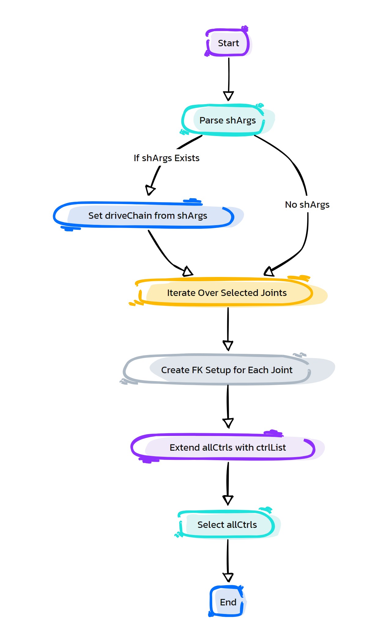
- HyperRig.as_GetFollicles(self, **shArgs)#
[shArgs: ]
Purpose:
:: Generates follicles on a mesh at the positions of selected vertices, allowing for dynamic attachment points.
Useful in hair and cloth simulation where follicles are needed for attaching dynamic elements to a mesh.
Operates based on the currently selected vertices.
- Param:
None # No explicit parameters are needed as the function operates based on the current vertex selection.
- Returns:
None # This function does not return any value but creates follicles on the mesh at selected vertices.
Code Examples:
>>> as_GetFollicles()
# Creates follicles on the mesh at the positions of currently selected vertices.
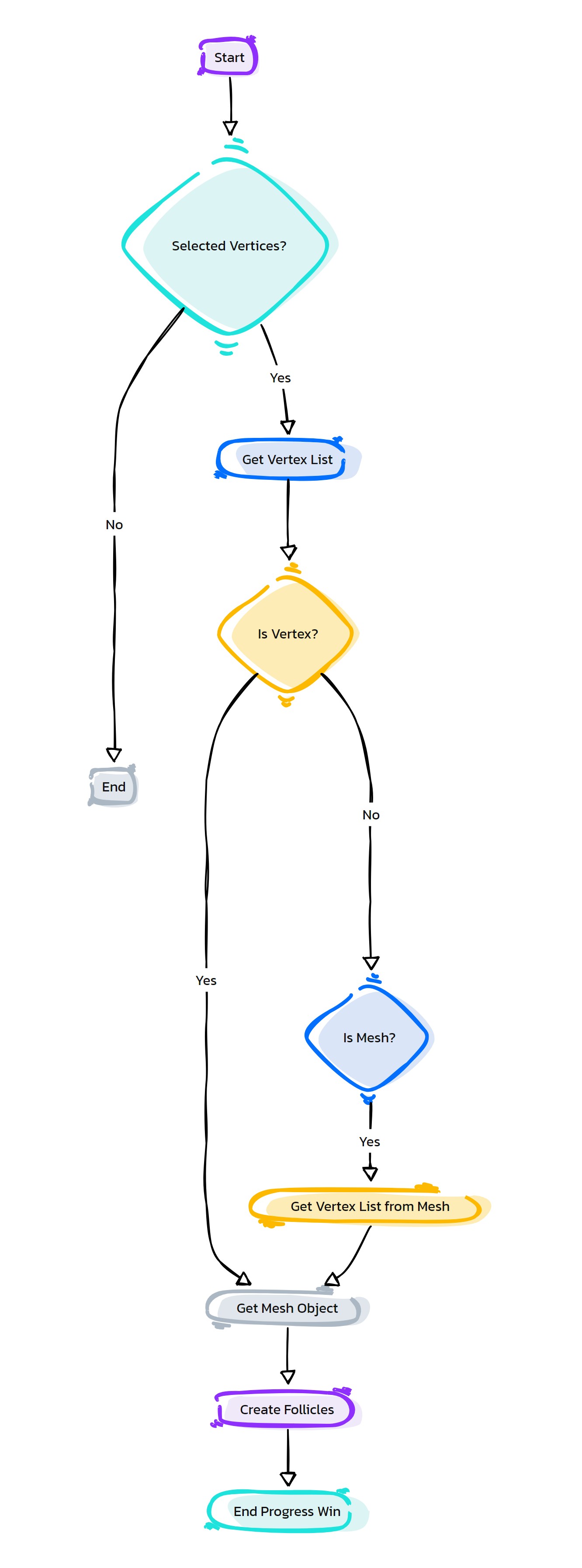
- HyperRig.as_GetFrameCtrl_FaceRig(self, **shArgs)#
[shArgs: ]
Purpose:
:: Generates frame controls for facial rigging based on user-defined names, enhancing facial animation capabilities.
Essential for facial rigging where frame controls provide precise manipulation of facial features.
User input is involved in defining control names through a prompt dialog.
- Param:
None # No explicit parameters are needed as the function operates based on user input for control names.
- Returns:
None # This function does not return any value but creates frame controls for facial rigging based on user-defined names.
Code Examples:
>>> as_GetFrameCtrl_FaceRig()
# Creates frame controls for facial rigging based on user-defined names.
graph TB Start[("fa:fa-play Start")] --> PromptName{"/fas:fa-keyboard Prompt for Control Name"} PromptName --"User provides names"--> SplitNames["/fas:fa-cut Split Names"] PromptName --"Action Cancelled"--> End[("fas:fa-stop End")] SplitNames --"Split names by commas and strip spaces"--> CreateFrameCtrls["/fas:fa-object-group Create Frame Controls"] CreateFrameCtrls --"Generate frame controls for facial rigging"--> End style Start fill:#00cc00,stroke:#000,stroke-width:3px style PromptName fill:#f0ad4e,stroke:#000,stroke-width:2px style SplitNames fill:#5bc0de,stroke:#000,stroke-width:2px style CreateFrameCtrls fill:#5cb85c,stroke:#000,stroke-width:2px style End fill:#ff6666,stroke:#000,stroke-width:3px- Flow Chart Description:
This flowchart illustrates the as_GetFrameCtrl_FaceRig function:
The process starts with a prompt for the user to input control names for facial rigging.
If names are provided, they are split and processed; if the action is cancelled, the process ends.
The function splits the input names by commas and trims any spaces.
Frame controls for facial rigging are then created based on the provided names.
The process concludes after the frame controls are created.
- HyperRig.as_GetLowResGeo(self, reduceCount=5000, **shArgs)#
[shArgs: ]
Purpose:
:: Generates a low-resolution version of the selected geometry, optimizing performance for tasks like rigging and simulation.
Ideal for scenarios where high-resolution meshes hinder performance, requiring a simplified version for efficient processing.
Provides control over the reduction count for the geometry simplification.
- Parameters:
reduceCount – <int, optional> #Specifies the number of reductions to be applied to the geometry. Default is 5000.
- Returns:
None # This function does not return any value but generates a low-resolution version of the selected geometry.
Code Examples:
>>> as_GetLowResGeo(5000)
# Generates a low-resolution version of the selected geometry with a reduction count of 5000.
graph TB Start[("fa:fa-play Start")] --> SelectGeometry["/fas:fa-mouse-pointer Select Geometry"] SelectGeometry --"Select mesh for reduction"--> InitializeReduction["/fas:fa-cog Initialize Reduction Process"] InitializeReduction --"Set reduction count"--> GenerateLowResGeo["/fas:fa-compress Generate Low-Res Geometry"] GenerateLowResGeo --"Create optimized geometry"--> End[("fas:fa-stop End")] style Start fill:#00cc00,stroke:#000,stroke-width:3px style SelectGeometry fill:#ffcc00,stroke:#000,stroke-width:2px style InitializeReduction fill:#99ccff,stroke:#000,stroke-width:2px style GenerateLowResGeo fill:#cc99ff,stroke:#000,stroke-width:2px style End fill:#ff6666,stroke:#000,stroke-width:3px- Flow Chart Description:
This flowchart illustrates the as_GetLowResGeo function:
The process begins with selecting the geometry that needs to be reduced in resolution.
The reduction process is initialized, setting up parameters for geometry optimization.
The specified reduction count is applied to generate the low-resolution version of the geometry.
The process completes with the creation of an optimized low-resolution geometry suitable for tasks like rigging and simulation.
- HyperRig.as_GetMirrorLoc(self, mirrorBehavior=1, axisList=['x', 'y'], objList=None, getExtraCtrl=False, **shArgs)#
[shArgs: ]
Purpose:
:: Creates mirrored locator(s) for a selected object or a list of objects, with optional behavior and axis specifications.
Useful in rigging for creating symmetrical setups, especially in character rigging.
Provides options for mirror behavior, axis selection, and processing additional control elements.
- Parameters:
mirrorBehavior – <int, optional> #Determines the behavior of the mirroring process. Default is 1.
axisList – <list of str, optional> #Specifies the axes for the mirroring process. Default is [‘x’, ‘y’].
objList – <list, optional> #A list of objects to be mirrored. If not provided, uses the current selection.
getExtraCtrl – <bool, optional> #Indicates whether to get additional control elements. Default is False.
- Returns:
None # This function does not return any value but creates mirrored locators based on the specified or selected objects.
Code Examples:
>>> as_GetMirrorLoc(1, ['x', 'y'], [object1, object2], False)
# Creates mirrored locators for the specified objects with the given mirror behavior and axis list, without additional control elements.
graph TB Start[("fa:fa-play Start")] --> CheckObjects{"/fas:fa-mouse-pointer Check Objects"} CheckObjects --"If object list is provided"--> ObjectLoop{"/fas:fa-repeat Object Loop"} CheckObjects --"If no objects provided"--> UseSelection["/fas:fa-object-group Use Selection"] UseSelection --> ObjectLoop ObjectLoop --"For each object in list"--> CheckPrefix{"/fas:fa-code-branch Check Prefix"} CheckPrefix --"Determine prefix for mirroring"--> CreateMirrorLocs["/fas:fa-map-marker-alt Create Mirror Locators"] CreateMirrorLocs --"Create mirrored locators"--> ReturnMirrorLocs["/fas:fa-undo Return Mirror Locators"] ReturnMirrorLocs --> End[("fas:fa-stop End")] CheckPrefix --"If extra control needed"--> DuplicateCtrl["/fas:fa-clone Duplicate Control"] DuplicateCtrl --"Duplicate and rename control"--> SnapRotation["/fas:fa-sync-alt Snap Rotation"] SnapRotation --"Align duplicated control"--> LockAttrs["/fas:fa-lock Lock Attributes"] LockAttrs --"Lock unnecessary attributes"--> MirrorCtrlShapes["/fas:fa-object-ungroup Mirror Control Shapes"] MirrorCtrlShapes --"Mirror shapes of original control"--> ReturnMirrorLocs style Start fill:#00cc00,stroke:#000,stroke-width:3px style CheckObjects fill:#f0ad4e,stroke:#000,stroke-width:2px style UseSelection fill:#f7ecb5,stroke:#000,stroke-width:2px style ObjectLoop fill:#5bc0de,stroke:#000,stroke-width:2px style CheckPrefix fill:#5cb85c,stroke:#000,stroke-width:2px style CreateMirrorLocs fill:#337ab7,stroke:#000,stroke-width:2px style ReturnMirrorLocs fill:#8fbc8f,stroke:#000,stroke-width:2px style DuplicateCtrl fill:#ff9999,stroke:#000,stroke-width:2px style SnapRotation fill:#ffcc00,stroke:#000,stroke-width:2px style LockAttrs fill:#cc99ff,stroke:#000,stroke-width:2px style MirrorCtrlShapes fill:#98fb98,stroke:#000,stroke-width:2px style End fill:#ff6666,stroke:#000,stroke-width:3px- Flow Chart Description:
This flowchart illustrates the as_GetMirrorLoc function:
The process starts by checking if a list of objects is provided. If not, it uses the current selection.
It loops through each object in the list or selection.
The function checks the prefix of each object to determine the correct mirroring criteria.
Mirrored locators are created based on the determined criteria.
If extra control is required, the process duplicates the control, snaps its rotation to the mirror locator, locks unnecessary attributes, and mirrors control shapes.
Finally, the mirrored locators are returned, completing the process.
- HyperRig.as_GetSliderCtrl_FaceRig(self, ctrlName=None, removeSuffix=False, **shArgs)#
[shArgs: ]
Purpose:
:: Creates slider controls for facial rigging, either based on a specified control name or user input, optionally removing suffixes.
Vital for facial rigging to create slider controls that allow for nuanced facial expressions.
Offers the flexibility to specify control names or use user input, with the option to remove suffixes from the control names.
- Parameters:
ctrlName – <str, optional> #The name of the control. If not provided, uses user input.
removeSuffix – <bool, optional> #Determines whether to remove suffixes from the control name. Default is False.
- Returns:
None # This function does not return any value but creates slider controls for facial rigging based on the specified or input control name.
Code Examples:
>>> as_GetSliderCtrl_FaceRig('Smile_Ctrl', True)
# Creates a slider control for facial rigging named 'Smile' by removing the suffix from the specified control name.
graph TB Start[("fa:fa-play Start")] --> CheckName{"/fas:fa-edit Check Control Name"} CheckName --"If ctrlName is not provided"--> PromptName{"/fas:fa-keyboard Prompt for Control Name"} CheckName --"If ctrlName is provided"--> RemoveSuffix["/fas:fa-scissors Remove Suffix"] PromptName --"User provides name"--> RemoveSuffix PromptName --"Action Cancelled"--> End[("fas:fa-stop End")] RemoveSuffix --"Remove suffix if specified"--> CreateSliderCtrl["/fas:fa-sliders-h Create Slider Control"] CreateSliderCtrl --"Generate slider control for facial rigging"--> End style Start fill:#00cc00,stroke:#000,stroke-width:3px style CheckName fill:#f0ad4e,stroke:#000,stroke-width:2px style PromptName fill:#d9534f,stroke:#000,stroke-width:2px style RemoveSuffix fill:#5bc0de,stroke:#000,stroke-width:2px style CreateSliderCtrl fill:#5cb85c,stroke:#000,stroke-width:2px style End fill:#ff6666,stroke:#000,stroke-width:3px- Flow Chart Description:
This flowchart illustrates the as_GetSliderCtrl_FaceRig function:
The process begins by checking if a control name is provided.
If not provided, the user is prompted to input a control name. If the action is cancelled, the process ends.
If a control name is provided or obtained, the function checks if the suffix needs to be removed based on user specification.
A slider control for facial rigging is then created using the specified or input control name.
The process concludes after the slider control is created.
- HyperRig.as_GetSliderCtrls_4Attrs(self, **shArgs)#
[shArgs: ]
Purpose:
:: Automates the creation of slider controls for specified attributes, streamlining the facial rigging process.
Useful in facial rigging where multiple slider controls are required to drive various facial attributes.
The function targets user-selected attributes for slider control creation.
- Param:
None # No explicit parameters are needed as the function operates based on user-selected attributes.
- Returns:
None # This function does not return any value but creates slider controls for the selected attributes.
Code Examples:
>>> as_GetSliderCtrls_4Attrs()
# Creates slider controls for user-selected attributes, enhancing the facial rigging setup.
graph TB Start[("fa:fa-play Start")] --> CheckSelection{"/fas:fa-mouse-pointer Check Selection"} CheckSelection --"If attributes are selected"--> StartProgress["/fas:fa-spinner Start Progress"] CheckSelection --"If no attributes are selected"--> Error[("/fas:fa-exclamation-triangle Error")] StartProgress --> CreateSliderCtrls{"/fas:fa-sliders-h Create Slider Controls"} CreateSliderCtrls --"For each selected attribute"--> CreateSDK["/fas:fa-cogs Create SDK"] CreateSDK --> LockAttrs["/fas:fa-lock Lock Attributes"] LockAttrs --"Lock unnecessary attributes"--> MoveCtrl["/fas:fa-arrows-alt Move Control"] MoveCtrl --"Position control"--> UpdateProgress["/fas:fa-sync Update Progress"] UpdateProgress --"Update progress for each attribute"--> CreateSliderCtrls CreateSliderCtrls --"After creating all controls"--> EndProgress["/fas:fa-flag-checkered End Progress"] EndProgress --"End progress window"--> End[("fas:fa-stop End")] style Start fill:#00cc00,stroke:#000,stroke-width:3px style CheckSelection fill:#f0ad4e,stroke:#000,stroke-width:2px style Error fill:#d9534f,stroke:#000,stroke-width:2px style StartProgress fill:#5bc0de,stroke:#000,stroke-width:2px style CreateSliderCtrls fill:#5cb85c,stroke:#000,stroke-width:2px style CreateSDK fill:#337ab7,stroke:#000,stroke-width:2px style LockAttrs fill:#f7ecb5,stroke:#000,stroke-width:2px style MoveCtrl fill:#f0e68c,stroke:#000,stroke-width:2px style UpdateProgress fill:#8fbc8f,stroke:#000,stroke-width:2px style EndProgress fill:#98fb98,stroke:#000,stroke-width:2px style End fill:#ff6666,stroke:#000,stroke-width:3px- Flow Chart Description:
This flowchart illustrates the as_GetSliderCtrls_4Attrs function:
The process starts with a check for selected attributes.
If no attributes are selected, an error is displayed.
When attributes are selected, the function initiates a progress window.
It then creates slider controls for each selected attribute, setting up SDKs (Set Driven Keys) to link controls to attributes.
Unnecessary attributes on the controls are locked for cleaner user interaction.
Each control is repositioned for clarity and organization.
The progress is updated after each attribute is processed.
The process ends with the closing of the progress window.
- HyperRig.as_GetSpaceSwitch(self, constrainStr='parent', grpLevel=0, **shArgs)#
[shArgs: ]
Purpose:
:: Implements a space switch setup for selected objects, allowing for dynamic parenting and transformation spaces.
Essential in rigging for creating space switch setups that provide flexibility in animation.
Offers customization of the constraint type and group level for the space switch.
- Parameters:
constrainStr – <str, optional> #Specifies the type of constraint to be used for the space switch. Default is ‘parent’.
grpLevel – <int, optional> #Defines the group level for the space switch setup. Default is 0, which is determined by a UI option.
- Returns:
None # This function does not return any value but sets up space switching for the selected objects.
Code Examples:
>>> as_GetSpaceSwitch('parent', 0)
# Sets up a space switch with parent constraint for the selected objects, using the group level defined in the UI.
graph TB Start[("fa:fa-play Start")] --> CheckSelection{"/fas:fa-check-circle Check Selection"} CheckSelection --"If objects are selected"--> GetGrpLevel{"/fas:fa-layer-group Get Group Level"} CheckSelection --"If no objects selected"--> ErrorNoSelection["/fas:fa-exclamation-triangle Error: No Selection"] GetGrpLevel --"Retrieve group level"--> ConstrainSpaceSwitch["/fas:fa-link Constrain Space Switch"] ConstrainSpaceSwitch --"Apply space switch setup"--> CheckMirror{"/fas:fa-code-branch Check for Mirror Object"} CheckMirror --"If mirror object exists"--> ConfirmMirror["/fas:fa-question-circle Confirm Mirror Action"] ConfirmMirror --"If confirmed"--> CreateMirrorSpaceSwitch["/fas:fa-clone Create Mirror Space Switch"] CreateMirrorSpaceSwitch --"Apply space switch to mirror object"--> End[("fas:fa-stop End")] ConfirmMirror --"If not confirmed"--> End ErrorNoSelection --> End style Start fill:#00cc00,stroke:#000,stroke-width:3px style CheckSelection fill:#f0ad4e,stroke:#000,stroke-width:2px style GetGrpLevel fill:#5bc0de,stroke:#000,stroke-width:2px style ConstrainSpaceSwitch fill:#337ab7,stroke:#000,stroke-width:2px style CheckMirror fill:#5cb85c,stroke:#000,stroke-width:2px style ConfirmMirror fill:#ffcc00,stroke:#000,stroke-width:2px style CreateMirrorSpaceSwitch fill:#cc99ff,stroke:#000,stroke-width:2px style ErrorNoSelection fill:#ff9999,stroke:#000,stroke-width:2px style End fill:#ff6666,stroke:#000,stroke-width:3px- Flow Chart Description:
This flowchart illustrates the as_GetSpaceSwitch function:
The process begins by checking if objects are selected. If no objects are selected, an error is shown.
If objects are selected, it retrieves the group level for the space switch setup.
The function then applies the space switch setup to the selected objects.
It checks if a mirror object exists for the last selected object.
If a mirror object exists and is confirmed, the space switch setup is applied to the mirror object as well.
Finally, the process ends after setting up space switches on the selected and optionally the mirror objects.
- HyperRig.as_GetStickySkinCtrl(self, **shArgs)#
[shArgs: ]
Purpose:
:: Creates a control that sticks to the surface of a skinned mesh, moving on top of any blend shapes applied to the mesh.
This function is intended for use on skinned meshes, especially those with blend shapes.
User interaction is required to define the control name through a prompt dialog.
- Param:
None # No explicit parameters are needed as the function operates based on user selection and input.
- Returns:
None # This function does not return any value but creates a control on the skin mesh based on user input.
Code Examples:
>>> as_GetStickySkinCtrl()
# Creates a sticky control on the selected skinned mesh based on user-defined name.
Creates Sticky Control on skin mesh. And control moves on top of blend shape. :Usage: Select 2 edges on skinned mesh (Blend shape mesh can be taken from first blend shape)
graph TB Start[("fa:fa-play Start")] --> SelectEdges["/fas:fa-mouse-pointer Select Edges"] SelectEdges --"Select two edges on skinned mesh"--> PromptName["/fas:fa-keyboard Prompt for Control Name"] PromptName --"Enter control name"--> CreateStickyControl["/fas:fa-sticky-note Create Sticky Control"] CreateStickyControl --"Control created"--> End[("fas:fa-stop End")] style Start fill:#00cc00,stroke:#000,stroke-width:3px style SelectEdges fill:#ffcc00,stroke:#000,stroke-width:2px style PromptName fill:#99ccff,stroke:#000,stroke-width:2px style CreateStickyControl fill:#cc99ff,stroke:#000,stroke-width:2px style End fill:#ff6666,stroke:#000,stroke-width:3px- Flow Chart Description:
This flowchart illustrates the as_GetStickySkinCtrl function:
The process starts by selecting two edges on a skinned mesh.
A prompt appears for the user to enter a name for the new control.
After the name is entered, a sticky control is created on the skinned mesh.
The control adheres to the surface, moving along with any blend shapes applied to the mesh.
- HyperRig.as_GroupIt(self, grpLevel=4, **shArgs)#
[shArgs: ]
Purpose:
:: Groups selected objects at a specified group level, organizing scene elements for better rigging and animation workflows.
Useful for riggers and animators in organizing and managing scene elements.
Allows specifying the group level for the grouping operation.
- Parameters:
grpLevel – <int, optional> #The level at which the selected objects are to be grouped. Default is 4.
- Returns:
None # This function does not return any value but groups the selected objects at the specified level.
Code Examples:
>>> as_GroupIt(4)
# Groups the selected objects at group level 4.
graph TB Start[("fa:fa-play Start")] --> CheckSelection{"/fas:fa-check-circle Check Selection"} CheckSelection --"If objects are selected"--> GroupObjects{"/fas:fa-object-group Group Objects"} CheckSelection --"If no objects selected"--> ErrorNoSelection["/fas:fa-exclamation-triangle Error: No Selection"] GroupObjects --"Group each selected object"--> End[("fas:fa-stop End")] ErrorNoSelection --> End style Start fill:#00cc00,stroke:#000,stroke-width:3px style CheckSelection fill:#f0ad4e,stroke:#000,stroke-width:2px style GroupObjects fill:#5bc0de,stroke:#000,stroke-width:2px style ErrorNoSelection fill:#ff9999,stroke:#000,stroke-width:2px style End fill:#ff6666,stroke:#000,stroke-width:3px- Flow Chart Description:
This flowchart illustrates the as_GroupIt function:
The process begins by checking if objects are selected. If no objects are selected, an error is shown.
If objects are selected, each object is grouped at the specified group level.
The process concludes after grouping the selected objects.
- HyperRig.as_HasMeshContains(self, **shArgs)#
[shArgs: ]
Purpose:
:: Checks if the selected mesh contains specific objects, aiding in collision detection and spatial analysis within the scene.
Useful in rigging and animation for verifying spatial relationships and collisions between objects and meshes.
Operates based on the current selection of objects and a target mesh.
- Param:
None # No explicit parameters are needed as the function operates based on the current selection and a target mesh.
- Returns:
None # This function does not return any value but checks and selects objects that are contained within the selected mesh.
Code Examples:
>>> as_HasMeshContains()
# Checks and selects objects from the current selection that are contained within the last selected mesh.
graph TB Start[("fa:fa-play Start")] --> CheckSelection{"/fas:fa-check-circle Check Selection"} CheckSelection --"Check each selected object"--> EvaluateContainment{"/fas:fa-search Evaluate Containment"} EvaluateContainment --"Evaluate if object is contained in the mesh"--> AddToSetList{"/fas:fa-plus-circle Add To Set List"} AddToSetList --"Add contained objects to set list"--> SelectSetList{"/fas:fa-mouse-pointer Select Set List"} SelectSetList --"Select objects from set list"--> End[("fas:fa-stop End")] style Start fill:#00cc00,stroke:#000,stroke-width:3px style CheckSelection fill:#f0ad4e,stroke:#000,stroke-width:2px style EvaluateContainment fill:#5bc0de,stroke:#000,stroke-width:2px style AddToSetList fill:#5cb85c,stroke:#000,stroke-width:2px style SelectSetList fill:#0275d8,stroke:#000,stroke-width:2px style End fill:#ff6666,stroke:#000,stroke-width:3px- Flow Chart Description:
This flowchart illustrates the as_HasMeshContains function:
The process starts by checking each object in the selection.
It evaluates whether each object is contained within the last selected mesh.
Objects found to be contained within the mesh are added to a set list.
Finally, the objects in the set list are selected.
- HyperRig.as_HyperRig(self, **shArgs)#
[shArgs: ]
Purpose:
:: Initializes and configures the as_HyperRig window and its components, providing a comprehensive rigging toolset for Autodesk Maya.
Centralizes various rigging tools and utilities within a single interface for efficiency and ease of use.
Dynamically adjusts the interface and available tools based on Maya version and other system parameters.
Global Variables: - topGrp, transGrp, jntGrp, geoGrp, ikGrp: Used for categorizing different types of rig elements. - rootCtrlGrp, LHandCtrlGrp, RHandCtrlGrp, LLegCtrlGrp, RLegCtrlGrp: Groups for organizing control rigs. - L_IK_HandName, R_IK_HandName, L_FK_HandName, R_FK_HandName, L_HandName, R_HandName: Naming conventions for hand control rigs.
- Returns:
None # This function does not return any value but creates and configures the as_HyperRig window and its components.
Code Examples:
>>> as_HyperRig()
# Initializes and configures the as_HyperRig window for rigging tasks.
graph TB Start[("fa:fa-play Start")] --> Initialize[("/fas:fa-power-off Initialize as_HyperRig Window")] Initialize --> CheckVersion[("/fas:fa-check Check Maya Version")] CheckVersion --"If Maya version >= 2016"--> SetupNewVersion[("/fas:fa-cogs Setup Interface for Newer Version")] CheckVersion --"Else"--> SetupOldVersion[("/fas:fa-cogs Setup Interface for Older Version")] SetupNewVersion --> CreateWindow[("/fas:fa-window-maximize Create as_HyperRig Window")] SetupOldVersion --> CreateWindow CreateWindow --> End[("fas:fa-stop End")] style Start fill:#00cc00,stroke:#000,stroke-width:3px style Initialize fill:#ffcc00,stroke:#000,stroke-width:2px style CheckVersion fill:#ff9999,stroke:#000,stroke-width:2px style SetupNewVersion fill:#99ccff,stroke:#000,stroke-width:2px style SetupOldVersion fill:#99ccff,stroke:#000,stroke-width:2px style CreateWindow fill:#cc99ff,stroke:#000,stroke-width:2px style End fill:#ff6666,stroke:#000,stroke-width:3px- Flow Chart Description:
This flowchart illustrates the as_HyperRig function:
The process starts with initializing the as_HyperRig window.
It checks the version of Maya being used.
Depending on the Maya version, it sets up the interface accordingly.
Finally, it creates the as_HyperRig window.
- HyperRig.as_HyperRig_AdjustUI(self, action='expand', innerFrame='as_Controls1_FL', midFrame='as_Controls_FL', adjHeight=80, **shArgs)#
[shArgs: ]
Purpose:
:: Dynamically adjusts the UI elements of the HyperRig tool, enhancing user experience and interface usability.
Useful in tool development for creating adaptable and user-friendly interfaces.
Allows for expanding or contracting specific UI elements based on user actions.
- Parameters:
action – <str, optional> #Specifies the action to perform on the UI (‘expand’ or ‘contract’). Default is ‘expand’.
innerFrame – <str, optional> #The inner frame layout to adjust. Default is ‘as_Controls1_FL’.
midFrame – <str, optional> #The middle frame layout to adjust. Default is ‘as_Controls_FL’.
adjHeight – <int, optional> #The adjustment height for the UI elements. Default is 80.
- Returns:
None # This function does not return any value but adjusts the UI elements of the HyperRig tool based on the specified parameters.
Code Examples:
>>> as_HyperRig_AdjustUI('expand', 'as_Controls1_FL', 'as_Controls_FL', 80)
# Expands the specified UI elements of the HyperRig tool by 80 units.
graph TB Start[("fa:fa-play Start")] --> CheckAction{"/fas:fa-tasks Check Action"} CheckAction --"If action is expand"--> ExpandUI{"/fas:fa-expand-arrows-alt Expand UI"} CheckAction --"If action is contract"--> ContractUI{"/fas:fa-compress-arrows-alt Contract UI"} ExpandUI --"Expand inner and mid frames"--> AdjustMainWindowExpand{"/fas:fa-window-maximize Adjust Main Window"} ContractUI --"Contract inner and mid frames"--> AdjustMainWindowContract{"/fas:fa-window-minimize Adjust Main Window"} AdjustMainWindowExpand --"Adjust main window height for expansion"--> End[("fas:fa-stop End")] AdjustMainWindowContract --"Adjust main window height for contraction"--> End style Start fill:#00cc00,stroke:#000,stroke-width:3px style CheckAction fill:#f0ad4e,stroke:#000,stroke-width:2px style ExpandUI fill:#5bc0de,stroke:#000,stroke-width:2px style ContractUI fill:#d9534f,stroke:#000,stroke-width:2px style AdjustMainWindowExpand fill:#5cb85c,stroke:#000,stroke-width:2px style AdjustMainWindowContract fill:#5cb85c,stroke:#000,stroke-width:2px style End fill:#ff6666,stroke:#000,stroke-width:3px- Flow Chart Description:
This flowchart illustrates the as_HyperRig_AdjustUI function:
The process starts by checking the specified action (expand or contract).
Based on the action, it either expands or contracts the inner and mid frames of the UI.
The main window height is then adjusted accordingly for either expansion or contraction.
- HyperRig.as_IKFKSetup_SingleChain(self, stJnt=None, endJnt=None, poleDir='-z', solverType=1, poleDist=1.25, ikfkSwitch=None, **shArgs)#
[shArgs : sj=stJnt, ej=endJnt, pd=poleDir, st=solverType, pd=poleDist, is=ikfkSwitch]
Purpose:
:: Sets up an IK/FK switch for a single joint chain, typically used for limbs like arms or legs.
Provides animators with the flexibility to switch between IK and FK controls.
Essential for realistic and varied movements in character animations.
Customizable pole direction and solver type to fit various rigging scenarios.
- Parameters:
stJnt – <str> # Starting joint of the chain (e.g., shoulder joint).
endJnt – <str> # Ending joint of the chain (e.g., wrist joint).
poleDir – <str> # Direction for the pole vector control (‘x’, ‘y’, ‘z’, ‘-x’, ‘-y’, ‘-z’).
solverType – <int> # Type of IK solver used (1 for RP solver, etc.).
poleDist – <float> # Distance multiplier for the pole vector control.
ikfkSwitch – <str> # Optional control object for IK/FK switching.
- Returns:
None # This function does not return a value but sets up IK/FK controls for a joint chain.
Code Examples:
>>> as_IKFKSetup_SingleChain(stJnt='shoulderJnt', endJnt='wristJnt', poleDir='-z', solverType=1, poleDist=1.25, ikfkSwitch='armSwitchCtrl')
# Sets up IK/FK switch for an arm with specified parameters.
graph TB Start[("fa:fa-play Start")] --> InitializeParameters["/fas:fa-cogs Initialize Parameters"] InitializeParameters --> CheckStartJoint{"/fas:fa-question-circle Check Start Joint"} CheckStartJoint --"If Start Joint Provided"--> CreatePoleCtrl["/fas:fa-location-arrow Create Pole Ctrl"] CheckStartJoint --"If Start Joint Not Provided"--> ErrorNoStartJoint["/fas:fa-exclamation-triangle Error: No Start Joint"] CreatePoleCtrl --> SetPoleDirection{"/fas:fa-arrows-alt Set Pole Direction"} SetPoleDirection --> CreateIK["/fas:fa-link Create IK"] CreateIK --> CreateIKCtrl["/fas:fa-hand-rock Create IK Ctrl"] CreateIKCtrl --> CheckIKFKSwitch{"/fas:fa-toggle-on Check IK/FK Switch"} CheckIKFKSwitch --"If IK/FK Switch Provided"--> SetupIKFKSwitch["/fas:fa-exchange-alt Setup IK/FK Switch"] CheckIKFKSwitch --"If No IK/FK Switch"--> ErrorNoIKFKSwitch["/fas:fa-exclamation-triangle Error: No IK/FK Switch"] SetupIKFKSwitch --> CreateFKCtrl["/fas:fa-cube Create FK Ctrl"] CreateFKCtrl --> ConnectFKCtrl["/fas:fa-link Connect FK Ctrl"] ConnectFKCtrl --> FinalizeSetup["/fas:fa-check-circle Finalize Setup"] ErrorNoStartJoint --> End["/fas:fa-stop End"] ErrorNoIKFKSwitch --> End FinalizeSetup --> End style Start fill:#00cc00,stroke:#000,stroke-width:3px style InitializeParameters fill:#ffcc00,stroke:#000,stroke-width:2px style CheckStartJoint fill:#ff9999,stroke:#000,stroke-width:2px style CreatePoleCtrl fill:#99ccff,stroke:#000,stroke-width:2px style SetPoleDirection fill:#cc99ff,stroke:#000,stroke-width:2px style CreateIK fill:#99ff99,stroke:#000,stroke-width:2px style CreateIKCtrl fill:#ffcc99,stroke:#000,stroke-width:2px style CheckIKFKSwitch fill:#ccffcc,stroke:#000,stroke-width:2px style SetupIKFKSwitch fill:#99ccff,stroke:#000,stroke-width:2px style CreateFKCtrl fill:#cc99ff,stroke:#000,stroke-width:2px style ConnectFKCtrl fill:#99ff99,stroke:#000,stroke-width:2px style FinalizeSetup fill:#ffcc99,stroke:#000,stroke-width:2px style ErrorNoStartJoint fill:#ff9999,stroke:#000,stroke-width:2px style ErrorNoIKFKSwitch fill:#cc99ff,stroke:#000,stroke-width:2px style End fill:#ff6666,stroke:#000,stroke-width:3px- Flow Chart Description:
This flowchart illustrates the as_IKFKSetup_SingleChain function:
The process starts by initializing parameters like stJnt, endJnt, poleDir, solverType, poleDist, and ikfkSwitch.
- Checks if a start joint is provided.
If a start joint is provided, it creates a pole control.
If no start joint is provided, an error message is displayed.
Sets the direction for the pole vector control.
Creates IK handles for the joint chain.
Creates and positions the IK control.
- Checks if an IK/FK switch control is provided.
If provided, sets up the IK/FK switch mechanism.
If not provided, an error message is displayed.
Creates FK controls for the joint chain.
Connects FK controls to the respective joints.
Finalizes the IK/FK setup.
Completes the process and ends.
- HyperRig.as_ImportSDKs(self, **shArgs)#
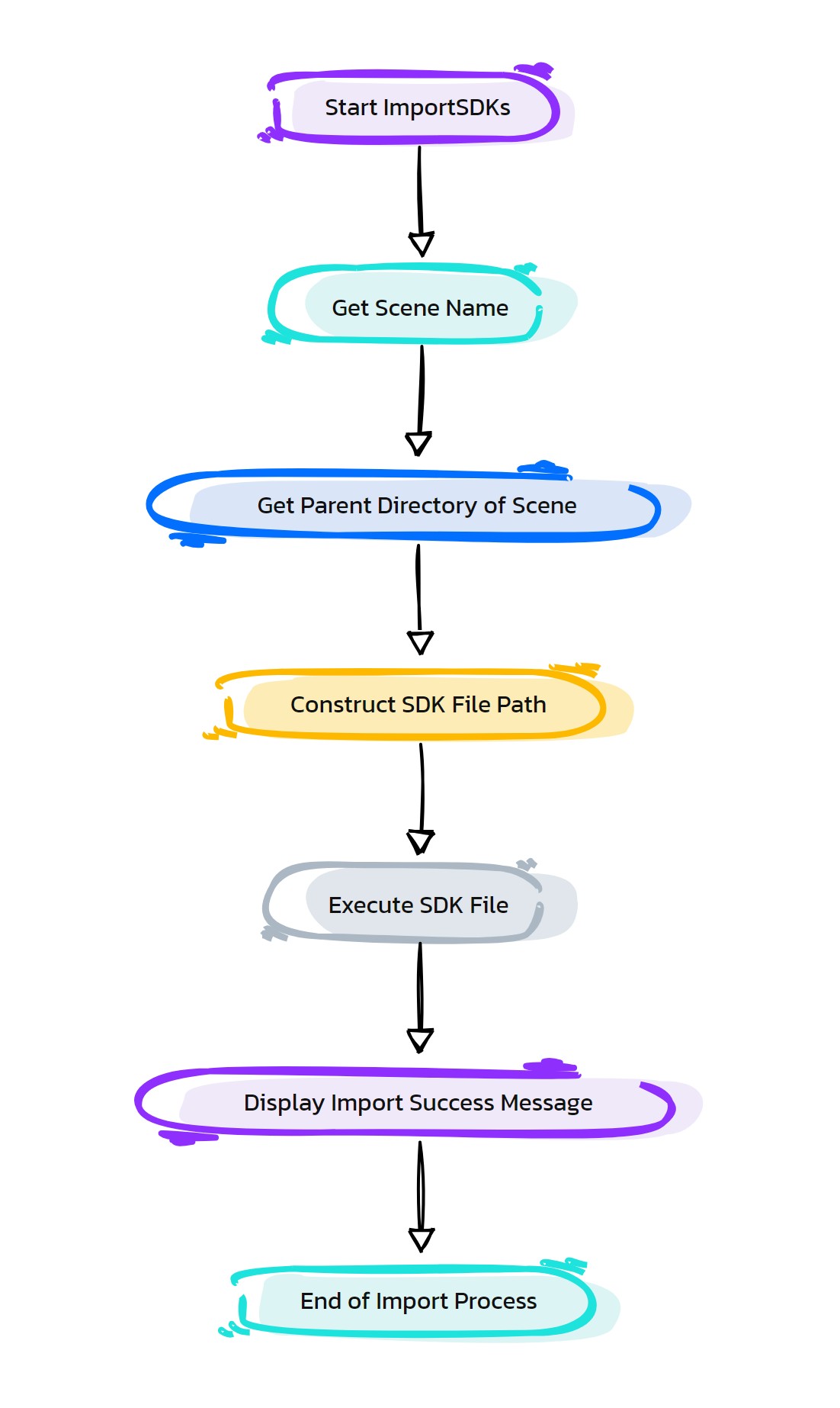
Purpose:
:: Imports Set Driven Keys (SDKs) from a specified file into the current Maya scene.
Streamlines the process of transferring SDKs between different scenes or versions of a character rig.
Ensures consistency and accuracy in SDK setups across multiple rigs or iterations.
Reduces the time and effort required to recreate complex SDK setups manually.
- Returns:
None # This function does not return a value but imports SDKs into the current scene.
Code Examples:
>>> as_ImportSDKs()
# Imports SDKs from the specified file into the current Maya scene.
graph TB Start[("fa:fa-play Start")] --> GetCurrentScene["/fas:fa-file-code GetCurrent Scene"] GetCurrentScene --> DetermineSDKFilePath["/fas:fa-folder-open Determine SDK File Path"] DetermineSDKFilePath --> CheckSDKFileExistence{"/fas:fa-question-circle Check SDK File Existence"} CheckSDKFileExistence --"If SDK File Exists"--> ImportSDKs["/fas:fa-file-import Import SDKs"] CheckSDKFileExistence --"If SDK File Does Not Exist"--> ErrorNoSDKFile["/fas:fa-exclamation-triangle Error: No SDK File Found"] ImportSDKs --> SuccessMessage["/fas:fa-check-circle Success Message"] ErrorNoSDKFile --> End[("fas:fa-stop End")] SuccessMessage --> End style Start fill:#00cc00,stroke:#000,stroke-width:3px style GetCurrentScene fill:#ffcc00,stroke:#000,stroke-width:2px style DetermineSDKFilePath fill:#ff9999,stroke:#000,stroke-width:2px style CheckSDKFileExistence fill:#99ccff,stroke:#000,stroke-width:2px style ImportSDKs fill:#cc99ff,stroke:#000,stroke-width:2px style ErrorNoSDKFile fill:#99ff99,stroke:#000,stroke-width:2px style SuccessMessage fill:#ffcc99,stroke:#000,stroke-width:2px style End fill:#ff6666,stroke:#000,stroke-width:3px- Flow Chart Description:
This flowchart illustrates the as_ImportSDKs function:
The process begins with obtaining the current scene’s name and path.
Determines the file path for the SDKs based on the current scene’s location.
- Checks if the SDK file exists at the determined location.
If the SDK file exists, proceeds to import SDKs into the current Maya scene.
If the SDK file does not exist, displays an error message.
Successful import of SDKs displays a confirmation message.
The process completes and ends.
- HyperRig.as_LockJoints(self, lockAll=0, unlockAll=0, invLock=1, parentChdCount=0, **shArgs)#
[shArgs: ]
Purpose:
:: Locks or unlocks the selected joints for skin weight painting in Autodesk Maya.
This function is useful for controlling the influence of specific joints on a skinned mesh during weight painting.
- Parameters:
lockAll – <bool> # Locks all joints if set to True.
unlockAll – <bool> # Unlocks all joints if set to True.
invLock – <bool> # Inverts the lock state of selected joints.
parentChdCount – <int> # Includes parent and child joints based on the specified count.
- Returns:
None # This function does not return any value but alters the lock state of joints.
Code Examples:
>>> as_LockJoints(lockAll=True)
# Locks all joints for skin weight painting.
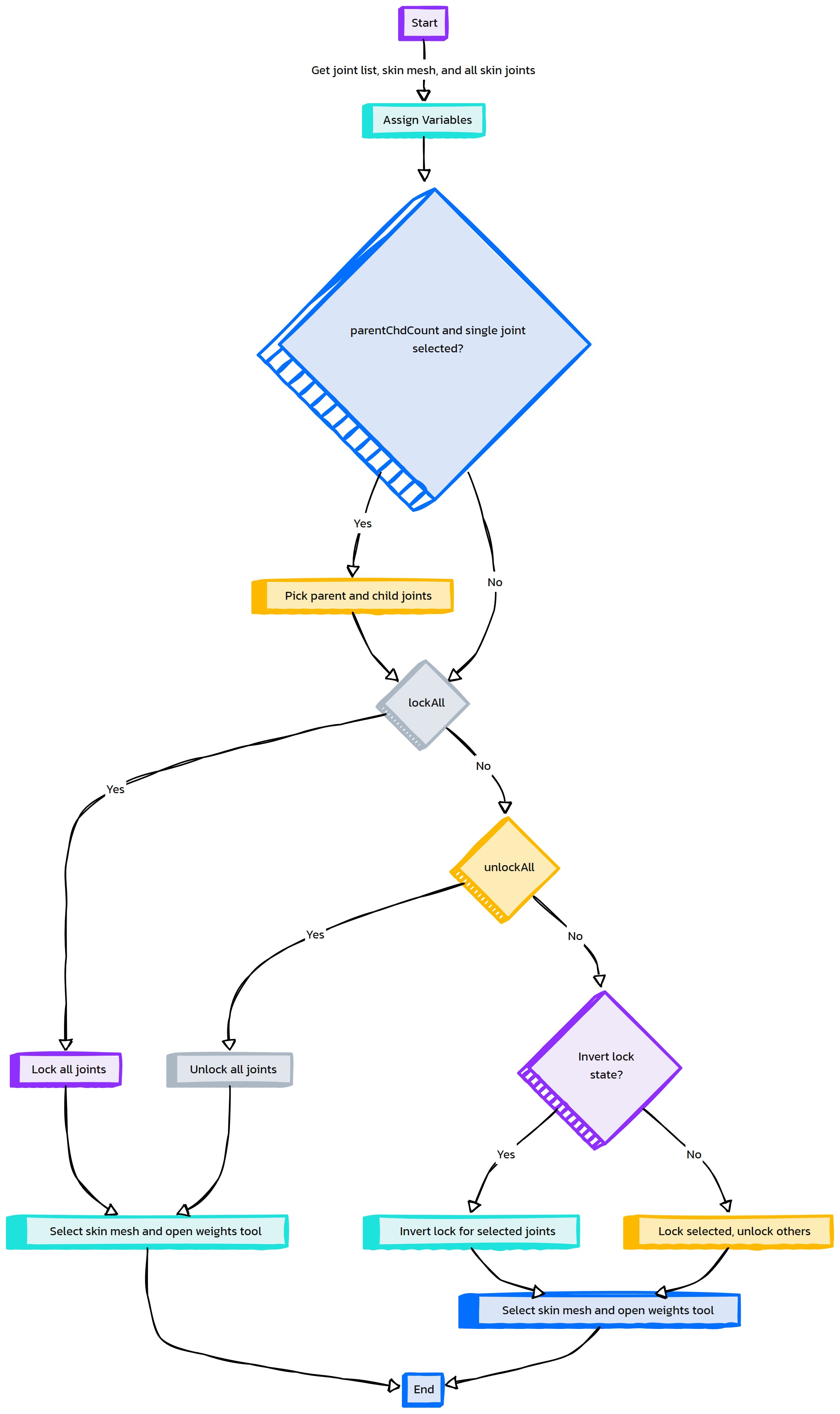
- HyperRig.as_MakeCtrlVisible(self, ctrlList=None, mesh=None, **shArgs)#
[shArgs: ]
Purpose:
:: Makes specified control curves visible on a given mesh in Autodesk Maya.
This function is used to enhance the visibility of control curves over a skinned mesh, especially during animation and rigging processes.
- Parameters:
ctrlList – <list> # List of control curves to be made visible.
mesh – <str> # Name of the mesh over which the controls will be made visible.
- Returns:
None # This function does not return any value but updates the visibility of control curves.
Code Examples:
>>> control_list = ["ctrl1", "ctrl2"]
>>> mesh_name = "character_mesh"
>>> as_MakeCtrlVisible(control_list, mesh_name)
# Makes specified control curves visible on the given mesh.
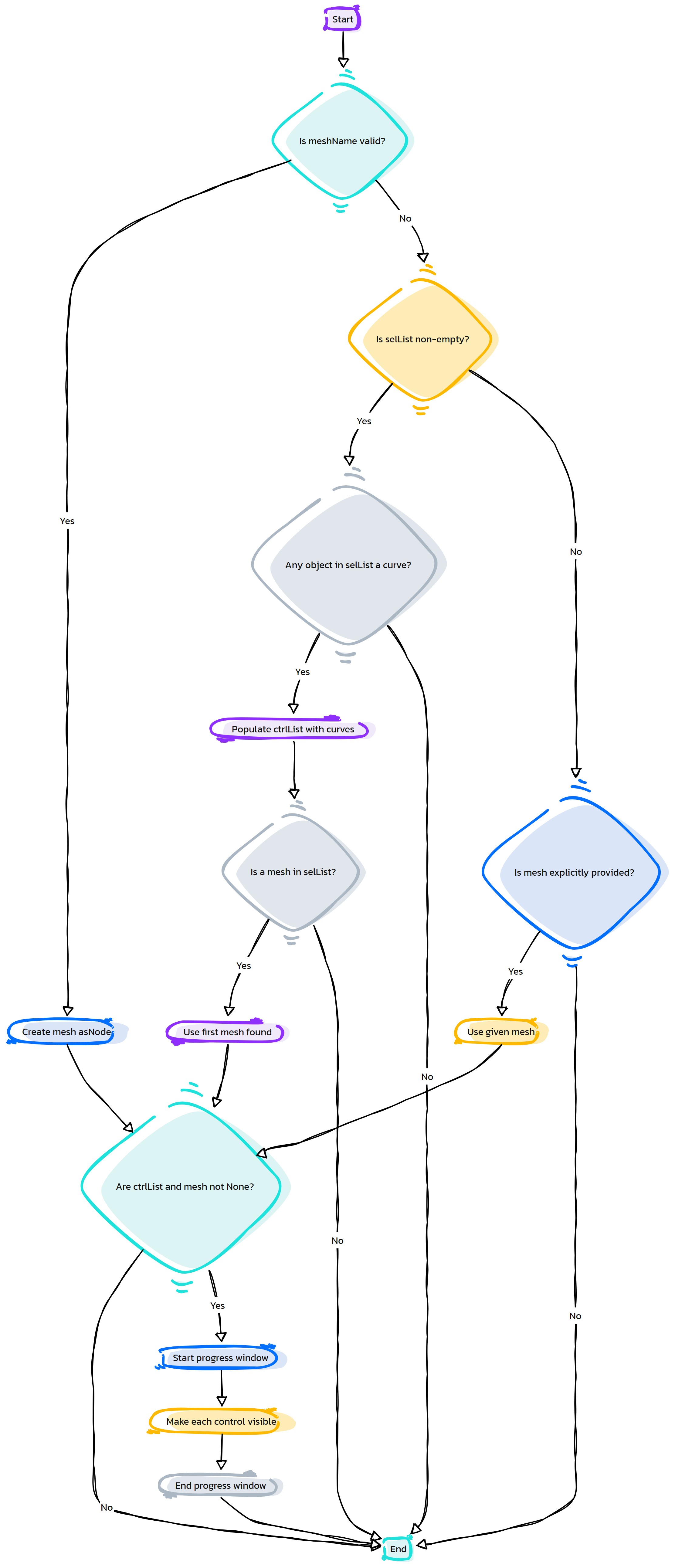
- HyperRig.as_MirrorCtrlShapes(self, mirrorLetters=False, **shArgs)#
[shArgs: ]
Purpose:
:: Mirrors the shapes of selected control curves in Autodesk Maya.
This function is essential in rigging, especially when creating symmetrical control setups for characters or objects.
- Parameters:
mirrorLetters – <bool> # Determines if the lettering on the controls should be mirrored.
- Returns:
None # This function does not return any value but mirrors the shapes of selected control curves.
Code Examples:
>>> as_MirrorCtrlShapes(mirrorLetters=True)
# Mirrors the shapes of selected control curves along with their lettering.
graph TB Start[("fa:fa-play Start")] --> GetSelectedControls[/fas:fa-mouse-pointer Get Selected Controls/] GetSelectedControls --> CheckMirrorLetters{{"/fas:fa-question-circle Check Mirror Letters"}} CheckMirrorLetters --"Mirror Letters"--> LoopThroughControlsLetters{{"/fas:fa-sync-alt Loop Through Controls (Letters)"}} CheckMirrorLetters --"No Mirror Letters"--> LoopThroughControlsNoLetters{{"/fas:fa-sync-alt Loop Through Controls (No Letters)"}} LoopThroughControlsLetters --> DetermineSideLetters[("/fas:fa-exchange-alt Determine Side (Letters)")] DetermineSideLetters --> MirrorControlShapesLetters[("/fas:fa-arrows-alt-h Mirror Control Shapes (Letters)")] MirrorControlShapesLetters --> End[("fas:fa-stop-circle End")] LoopThroughControlsNoLetters --> DetermineSideNoLetters[("/fas:fa-exchange-alt Determine Side (No Letters)")] DetermineSideNoLetters --> MirrorControlShapesNoLetters[("/fas:fa-arrows-alt-h Mirror Control Shapes (No Letters)")] MirrorControlShapesNoLetters --> End style Start fill:#00cc00,stroke:#000,stroke-width:3px style GetSelectedControls fill:#5bc0de,stroke:#000,stroke-width:2px style CheckMirrorLetters fill:#ffcc00,stroke:#000,stroke-width:2px style LoopThroughControlsLetters fill:#f0ad4e,stroke:#000,stroke-width:2px style LoopThroughControlsNoLetters fill:#f0ad4e,stroke:#000,stroke-width:2px style DetermineSideLetters fill:#5cb85c,stroke:#000,stroke-width:2px style DetermineSideNoLetters fill:#5cb85c,stroke:#000,stroke-width:2px style MirrorControlShapesLetters fill:#99ccff,stroke:#000,stroke-width:2px style MirrorControlShapesNoLetters fill:#99ccff,stroke:#000,stroke-width:2px style End fill:#ff6666,stroke:#000,stroke-width:3px- Flow Chart Description:
This flowchart illustrates the as_MirrorCtrlShapes function:
The process starts by obtaining the list of selected control curves in Maya.
It then checks if letter mirroring is enabled.
Depending on the letter mirroring setting, it loops through the selected controls.
For each control, it determines the side (left, right, or other) based on its naming convention.
Finally, it mirrors the control shapes, either with or without letter mirroring as specified.
- HyperRig.as_MoveValuesToGrp(self, attrList=['t', 'r'], grpLevel=1, **shArgs)#
[shArgs: ]
Purpose:
:: Transfers transform attribute values (like translation, rotation) to a specified group level in Autodesk Maya.
This function is utilized in rigging to clean up control attributes by moving them up the hierarchy.
- Parameters:
attrList – <list> # List of attributes to be transferred (e.g., [‘t’, ‘r’] for translation and rotation).
grpLevel – <int> # Specifies the group level to which the attributes will be transferred.
- Returns:
None # This function does not return any value but transfers attribute values to the specified group level.
Code Examples:
>>> attributes = ['t', 'r']
>>> group_level = 1
>>> as_MoveValuesToGrp(attributes, group_level)
# Transfers translation and rotation values to the specified group level.
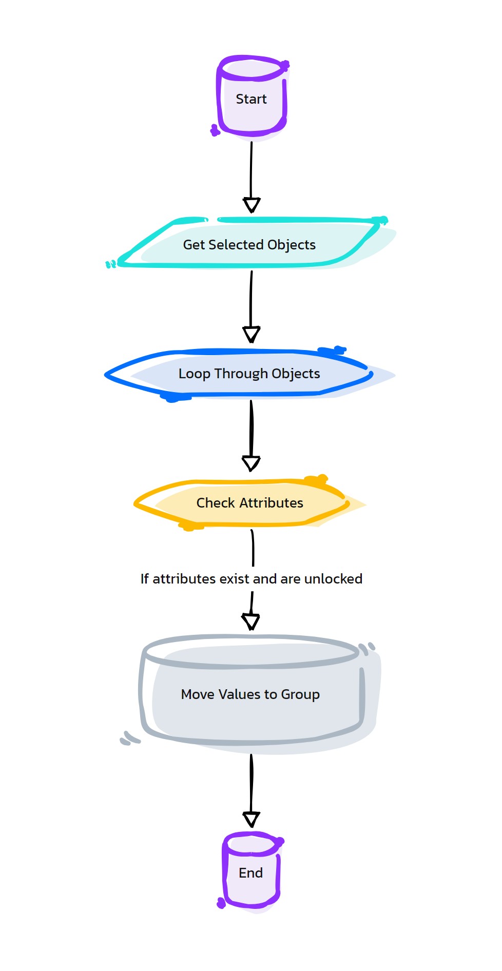
- HyperRig.as_PaintDisplay(self, val=1.0, **shArgs)#
[shArgs: ]
Purpose:
:: Adjusts the display settings for the Artisan Paint Skin Weights tool in Autodesk Maya.
This function is used to modify the display settings such as color range for better visibility during weight painting.
- Parameters:
val – <float> # The value to set for the upper color range in the Artisan Paint Skin Weights tool.
- Returns:
None # This function does not return any value but adjusts the display settings for skin weight painting.
Code Examples:
>>> upper_color_range = 1.0
>>> as_PaintDisplay(upper_color_range)
# Adjusts the upper color range for the Artisan Paint Skin Weights tool.
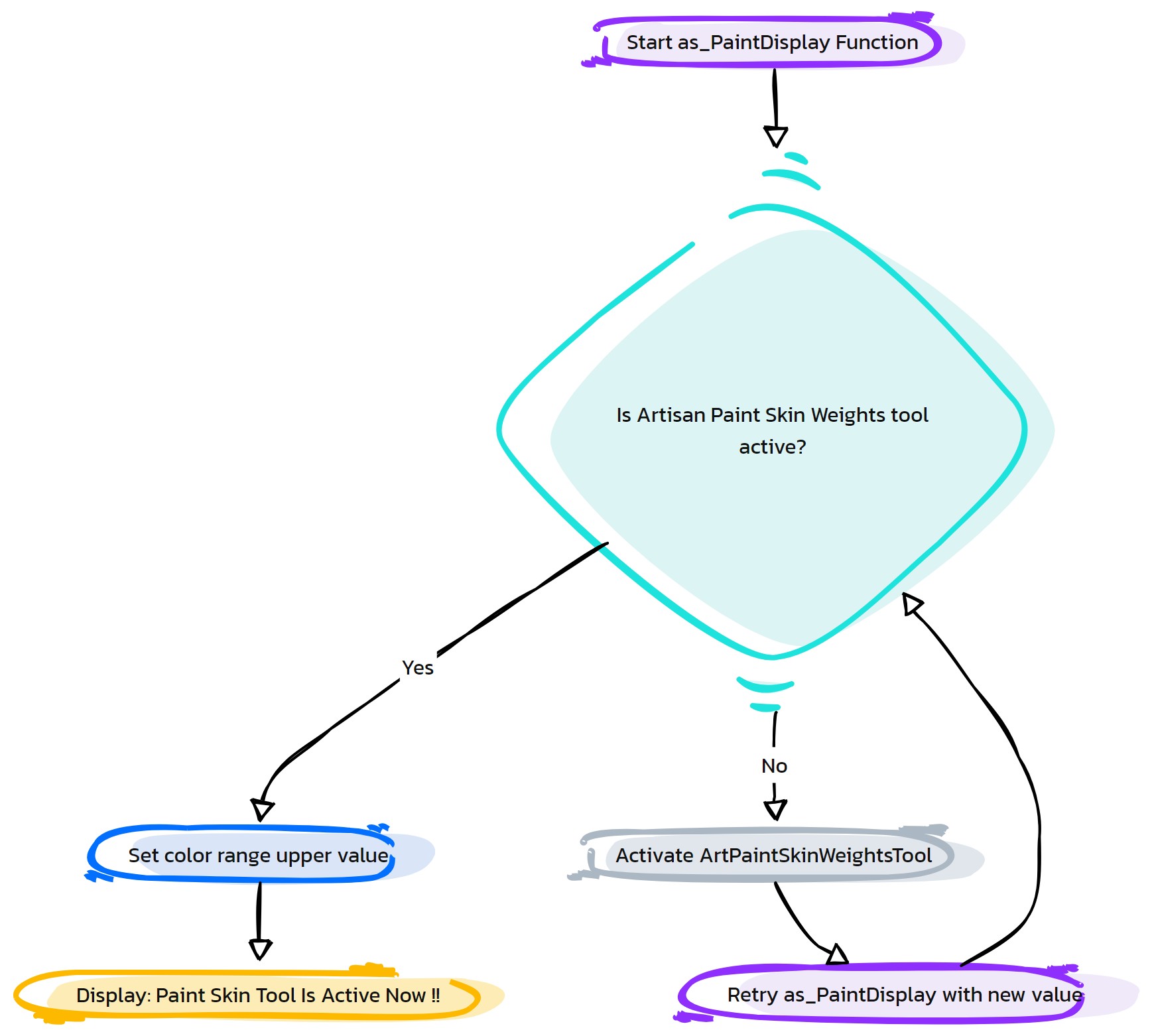
- HyperRig.as_PaintToggleColor(self, **shArgs)#
[shArgs: ]
Purpose:
:: Toggles the color display mode for the Artisan Paint Skin Weights tool in Autodesk Maya.
This function allows users to switch between different color display modes, enhancing the visibility during weight painting.
- Returns:
None # This function does not return any value but toggles the color display mode for the weight painting tool.
Code Examples:
>>> as_PaintToggleColor()
# Toggles the color display mode for the Artisan Paint Skin Weights tool.
graph TB Start[("fa:fa-play Start")] --> CheckColorRamp[("/fas:fa-palette Check Color Ramp")] CheckColorRamp --"Check if Color Ramp is Enabled" --> DisableColorRamp[("/fas:fa-toggle-off Disable Color Ramp")] CheckColorRamp --"Check if Color Ramp is Disabled" --> EnableColorRamp[("/fas:fa-toggle-on Enable Color Ramp")] DisableColorRamp --"Color Ramp Disabled" --> End[("fas:fa-stop-circle End")] EnableColorRamp --"Color Ramp Enabled" --> End style Start fill:#00cc00,stroke:#000,stroke-width:3px style CheckColorRamp fill:#ffcc00,stroke:#000,stroke-width:2px style DisableColorRamp fill:#d9534f,stroke:#000,stroke-width:2px style EnableColorRamp fill:#5cb85c,stroke:#000,stroke-width:2px style End fill:#ff6666,stroke:#000,stroke-width:3px- Flow Chart Description:
This flowchart illustrates the as_PaintToggleColor function:
The process starts by checking the current state of the Color Ramp in the Artisan Paint Skin Weights tool.
If the Color Ramp is enabled, it gets disabled to switch to the default color mode.
If the Color Ramp is disabled, it gets enabled to provide a gradient color display for weight painting.
- HyperRig.as_PrefixHI(self, selectedObjs=False, **shArgs)#
[shArgs : ol=objList, so=selectedObjs]
Purpose:
:: Adds a specified prefix to the hierarchy of selected objects in Maya.
Aids in organizing and categorizing objects within a scene based on their functionality or role.
Useful for batch renaming, especially in complex scenes or rigs.
Offers customization for prefix addition, targeting either selected objects or their entire hierarchy.
- Parameters:
objList – <list> # List of objects to prepend the prefix to.
selectedObjs – <bool, optional> # Determines if the prefix is added to only the selected objects (True) or their full hierarchy (False).
- Returns:
None # This function doesn’t return a value but renames objects in the scene.
Code Examples:
>>> as_PrefixHI(objList=['obj1', 'obj2'], selectedObjs=False)
# Adds a specified prefix to the entire hierarchy of the listed objects.
graph TB Start[("fa:fa-play Start")] --> GetSelectedObjects["/fas:fa-mouse-pointer Get Selected Objects"] GetSelectedObjects --> PromptPrefix["/fas:fa-text-height Prompt Prefix (Ctrl_)"] PromptPrefix --> CheckPromptResult{"/fas:fa-question-circle Check Prompt Result"} CheckPromptResult --"If OK is Clicked"--> GetPrefixText["/fas:fa-pencil-alt Get Prefix Text"] GetPrefixText --> PrependPrefix{"/fas:fa-plus-circle Prepend Prefix"} CheckPromptResult --"If Cancelled"--> ErrorActionCancelled["/fas:fa-exclamation-triangle Error: Action Cancelled"] PrependPrefix --"Prepend Prefix to Hierarchy"--> End[("fas:fa-stop End")] ErrorActionCancelled --> End style Start fill:#00cc00,stroke:#000,stroke-width:3px style GetSelectedObjects fill:#ffcc00,stroke:#000,stroke-width:2px style PromptPrefix fill:#ff9999,stroke:#000,stroke-width:2px style CheckPromptResult fill:#99ccff,stroke:#000,stroke-width:2px style GetPrefixText fill:#cc99ff,stroke:#000,stroke-width:2px style PrependPrefix fill:#99ff99,stroke:#000,stroke-width:2px style ErrorActionCancelled fill:#ff9999,stroke:#000,stroke-width:2px style End fill:#ff6666,stroke:#000,stroke-width:3px- Flow Chart Description:
This flowchart illustrates the as_PrefixHI function:
Begins by gathering a list of currently selected objects in Maya.
Prompts the user to enter a prefix, with a default suggestion of ‘Ctrl_’.
- After the prompt, checks if the user clicked ‘OK’ or cancelled the action.
If ‘OK’ is selected, retrieves the entered prefix text.
If the action is cancelled, displays an error message and terminates the process.
- If ‘OK’ is selected, prepends the entered prefix to each object in the hierarchy.
The prefix is added based on the selection of either the objects alone or their entire hierarchy.
- HyperRig.as_ReBuildBodyModule(self, **shArgs)#
[shArgs : ]
Purpose:
:: Rebuilds body modules in Autodesk Maya based on the selected module from the UI radio button groups.
This function dynamically rebuilds a body module based on user interface selections.
It supports rebuilding various body parts like Spine, Arm, Leg, Hand, Neck, Eyes, Tongue, and more.
Utilizes the HyperRig class to rebuild different types of rig modules.
- Parameters:
module – <int> #Module number selected from the UI, determines the type of body module to rebuild.
- Returns:
None #No return value, it rebuilds body modules in the Maya scene.
Code Examples:
>>> module = 1
>>> as_ReBuildBodyModule(module)
graph TB Start[("fa:fa-play Start")] --> CheckModule{"/fas:fa-check-circle Check Module"} CheckModule --"If module is provided" --> ReBuildModule{"/fas:fa-cogs Rebuild Module"} CheckModule --"If module is not provided" --> End[("fas:fa-stop End")] ReBuildModule --"Rebuild body module based on selected module"--> End style Start fill:#00cc00,stroke:#000,stroke-width:3px style CheckModule fill:#f0ad4e,stroke:#000,stroke-width:2px style ReBuildModule fill:#5cb85c,stroke:#000,stroke-width:2px style End fill:#ff6666,stroke:#000,stroke-width:3px- Flow Chart Description:
This flowchart illustrates the as_ReBuildBodyModule function:
The process starts by checking if a module number is selected from the UI.
If a module is selected, the function rebuilds a body module based on the selected module type, such as Spine, Arm, Leg, Hand, Neck, Eyes, Tongue, etc.
- HyperRig.as_ReBuildLeg_Setup(self, **shArgs)#
[shArgs : ]
Purpose:
:: Rebuilds the leg setup in Autodesk Maya.
This function confirms the action to rebuild the leg setup.
It performs operations like renaming setups, transferring skin, and cleaning up prefixed controls.
Utilizes various internal functions for manipulating and configuring nodes and hierarchies.
No specific arguments for this function.
- Returns:
None #No return value, it rebuilds the leg setup in the Maya scene.
Code Examples:
>>> as_ReBuildLeg_Setup()
graph TB Start[("fa:fa-play Start")] --> ConfirmAction{"/fas:fa-question-circle Confirm Action"} ConfirmAction --"If action confirmed" --> RenameSetup[("/fas:fa-edit Rename Setup")] ConfirmAction --"If action cancelled" --> End[("fas:fa-stop End")] RenameSetup --> BuildLegSetup["/fas:fa-hammer Build Leg Setup"] BuildLegSetup --> TransferSkinning[("/fas:fa-exchange-alt Transfer Skinning")] TransferSkinning --> UpdateCtrlShapes[("/fas:fa-sync Update Control Shapes")] UpdateCtrlShapes --> RemovePrefixed[("/fas:fa-trash-alt Remove Prefixed Items")] RemovePrefixed --> FinalMessage[("/fas:fa-flag-checkered Final Message")] FinalMessage --> End style Start fill:#00cc00,stroke:#000,stroke-width:3px style ConfirmAction fill:#f0ad4e,stroke:#000,stroke-width:2px style RenameSetup fill:#5bc0de,stroke:#000,stroke-width:2px style BuildLegSetup fill:#5cb85c,stroke:#000,stroke-width:2px style TransferSkinning fill:#f0ad4e,stroke:#000,stroke-width:2px style UpdateCtrlShapes fill:#d9534f,stroke:#000,stroke-width:2px style RemovePrefixed fill:#5bc0de,stroke:#000,stroke-width:2px style FinalMessage fill:#5cb85c,stroke:#000,stroke-width:2px style End fill:#ff6666,stroke:#000,stroke-width:3px- Flow Chart Description:
This flowchart illustrates the as_ReBuildLeg_Setup function:
The process starts with confirming the action to rebuild the leg setup.
Next, it renames existing setups by prefixing them and removes unwanted items.
The leg setup is then rebuilt and skinning is transferred to the new setup.
Control shapes are updated, and prefixed controls, joints, IKs, and other groups are removed.
Finally, a message is displayed indicating the successful rebuild of the leg setup.
- HyperRig.as_ReBuildLeg_Setup01(self, **shArgs)#
[shArgs : ]
Purpose:
:: Rebuilds and updates an existing leg rig setup in Autodesk Maya, incorporating improvements like bendy setup and toe joint creation.
This function is used to modify and enhance an existing leg rig, integrating new features and corrections.
It allows for the inclusion of a bendy setup, which adds flexibility and realism to the leg animations.
The option to create toe joints is provided, enabling more detailed foot and toe animations.
It is suitable for both biped and quadruped characters, making it versatile for various types of character rigs.
The function ensures that the updated rig maintains compatibility with the rest of the character’s rigging system.
- Returns:
None # This function updates an existing leg rig but doesn’t return a value.
Code Examples:
>>> as_ReBuildLeg_Setup01()
# Updates and enhances an existing leg rig with new features in Autodesk Maya.
graph TB Start[("fa:fa-play Start")] --> CheckHierarchy{"/fas:fa-check-circle Check Global Hierarchy"} CheckHierarchy --"Verify if Global_Control exists"--> CreateHierarchy["/fas:fa-sitemap Create Hierarchy"] CreateHierarchy --"Create Global_Control and necessary hierarchy"--> RebuildLegSetup["/fas:fa-tools Rebuild Leg Setup"] RebuildLegSetup --"Update existing leg rig"--> CheckBendySetup{"/fas:fa-question Check Bendy Setup"} CheckBendySetup --"If Bendy Setup is selected"--> ApplyBendySetup["/fas:fa-cogs Apply Bendy Setup"] CheckBendySetup --"No Bendy Setup"--> CheckToeSetup{"/fas:fa-question Check Toe Setup"} CheckToeSetup --"If Create Toe Setup is selected"--> CreateToeJoints["/fas:fa-shoe-prints Create Toe Joints"] CheckToeSetup --"No Toe Setup"--> End[("fas:fa-stop End")] ApplyBendySetup --> CheckToeSetup CreateToeJoints --> End style Start fill:#00cc00,stroke:#000,stroke-width:3px style CheckHierarchy fill:#ffcc00,stroke:#000,stroke-width:2px style CreateHierarchy fill:#99ccff,stroke:#000,stroke-width:2px style RebuildLegSetup fill:#ff9999,stroke:#000,stroke-width:2px style CheckBendySetup fill:#ffcc00,stroke:#000,stroke-width:2px style ApplyBendySetup fill:#99ccff,stroke:#000,stroke-width:2px style CheckToeSetup fill:#ffcc00,stroke:#000,stroke-width:2px style CreateToeJoints fill:#cc99ff,stroke:#000,stroke-width:2px style End fill:#ff6666,stroke:#000,stroke-width:3px- Flow Chart Description:
This flowchart illustrates the as_ReBuildLeg_Setup01 function:
The process begins with a check for the existence of a Global Control hierarchy.
If absent, a new hierarchy including Global Control is created.
The function then proceeds to update the existing leg rig.
It checks if the bendy setup is selected; if yes, it applies the bendy setup.
After applying the bendy setup, or if no bendy setup is chosen, it checks for toe setup.
If the toe setup is selected, toe joints are created; otherwise, the process ends.
The updated leg rig setup is now integrated, ensuring compatibility with the overall character rig.
- HyperRig.as_RebindSkinMeshes(self, **shArgs)#
[shArgs: ]
Purpose:
:: Rebinds skin meshes in Autodesk Maya, exporting and importing skin weights for the process.
Useful in rigging workflows for updating or modifying skinning on characters or objects.
- Returns:
None # This function does not return any value but rebinds skin meshes with updated skin weights.
Code Examples:
>>> as_RebindSkinMeshes()
# Rebinds skin meshes by exporting and importing skin weights.
graph TB Start[("fa:fa-play Start")] --> ConfirmAction{"/fas:fa-question-circle Confirm Re-Bind Method"} ConfirmAction --"Regular Re-Bind Method"--> ExportSkinWeights["/fas:fa-upload Export Skin Weights"] ConfirmAction --"Super-Fast Re-Bind Method"--> ExportSkinWeights ConfirmAction --"Action Cancelled"--> End[("fas:fa-stop-circle End")] ExportSkinWeights --> SelectTopGroupOrMeshes{"/fas:fa-object-group Select Top Group or Meshes"} SelectTopGroupOrMeshes --> DetermineSkinMeshes{"/fas:fa-search Determine Skin Meshes"} DetermineSkinMeshes --> StartRebinding{"/fas:fa-sync-alt Start Rebinding Process"} StartRebinding --> ForEachSkinMeshInList{"/fas:fa-cogs For Each Skin Mesh in List"} ForEachSkinMeshInList --> CheckDeleteHistory{"/fas:fa-check-square Check Delete History"} CheckDeleteHistory --"If Delete History"--> DeleteMeshHistory["/fas:fa-trash-alt Delete Mesh History"] CheckDeleteHistory --"If Not Delete History"--> DeleteSkinCluster["/fas:fa-trash-alt Delete Skin Cluster"] DeleteMeshHistory --> BindSkin["/fas:fa-link Bind Skin"] DeleteSkinCluster --> BindSkin BindSkin --> ProgressSkinMeshRebind{"/fas:fa-spinner Progress Skin Mesh Rebind"} ProgressSkinMeshRebind --> ImportSkinWeights["/fas:fa-download Import Skin Weights"] ImportSkinWeights --> End style Start fill:#00cc00,stroke:#000,stroke-width:3px style ConfirmAction fill:#f0ad4e,stroke:#000,stroke-width:2px style ExportSkinWeights fill:#5bc0de,stroke:#000,stroke-width:2px style SelectTopGroupOrMeshes fill:#5cb85c,stroke:#000,stroke-width:2px style DetermineSkinMeshes fill:#ffcc99,stroke:#000,stroke-width:2px style StartRebinding fill:#d9534f,stroke:#000,stroke-width:2px style ForEachSkinMeshInList fill:#f0ad4e,stroke:#000,stroke-width:2px style CheckDeleteHistory fill:#5bc0de,stroke:#000,stroke-width:2px style DeleteMeshHistory fill:#5cb85c,stroke:#000,stroke-width:2px style DeleteSkinCluster fill:#ffcc99,stroke:#000,stroke-width:2px style BindSkin fill:#d9534f,stroke:#000,stroke-width:2px style ProgressSkinMeshRebind fill:#f0ad4e,stroke:#000,stroke-width:2px style ImportSkinWeights fill:#5bc0de,stroke:#000,stroke-width:2px style End fill:#ff6666,stroke:#000,stroke-width:3px- Flow Chart Description:
This flowchart illustrates the as_RebindSkinMeshes function:
Starts by confirming the method for re-binding skin (Regular or Super-Fast).
If action is cancelled, the process ends.
Exports skin weights for the skin meshes.
Selects the top group or individual meshes.
Determines which meshes are skinned.
Begins the re-binding process for each skin mesh in the list.
- Checks if delete history is enabled.
If delete history is enabled, deletes the mesh history.
If not, deletes the existing skin cluster.
Binds skin to the mesh with updated weights.
Shows progress for each skin mesh being rebound.
Imports the skin weights for the rebound meshes.
Concludes the re-binding process.
- HyperRig.as_RemoveInvSkinJntWgts(self, **shArgs)#
[shArgs: ]
Purpose:
:: Removes inverse skin joint weights for selected vertices or joints in Autodesk Maya.
This function is used in skinning workflows to clean up or adjust skin weights on a mesh.
- Returns:
None # This function does not return any value but removes inverse skin joint weights from selected vertices or joints.
Code Examples:
>>> as_RemoveInvSkinJntWgts()
# Removes inverse skin joint weights for the current selection.
graph TB Start[("fa:fa-play Start")] --> CheckMesh[("/fas:fa-cube Check Mesh Existence")] CheckMesh --"If SkinMesh exists" --> CheckSelection{"/fas:fa-question-circle Check Selection"} CheckMesh --"If SkinMesh doesn't exist" --> Error[("/fas:fa-exclamation-triangle Error: Enter 'SkinMesh' in UI")] CheckSelection --"If Joints are selected" --> LockJoints[("/fas:fa-lock Lock Joints")] CheckSelection --"If Vertices are selected" --> SelectVertices[("/fas:fa-object-group Select Vertices")] LockJoints --> SelectInverseJoints[("/fas:fa-hand-point-up Select Inverse Joints")] SelectVertices --> SelectInverseJoints SelectInverseJoints --> PaintWeights[("/fas:fa-paint-brush Skin Paint Selected Joints")] PaintWeights --"Set weights to 0.0" --> End[("fas:fa-stop-circle End")] style Start fill:#00cc00,stroke:#000,stroke-width:3px style CheckMesh fill:#ffcc00,stroke:#000,stroke-width:2px style Error fill:#d9534f,stroke:#000,stroke-width:2px style CheckSelection fill:#ffcc00,stroke:#000,stroke-width:2px style LockJoints fill:#5cb85c,stroke:#000,stroke-width:2px style SelectVertices fill:#5cb85c,stroke:#000,stroke-width:2px style SelectInverseJoints fill:#f0ad4e,stroke:#000,stroke-width:2px style PaintWeights fill:#337ab7,stroke:#000,stroke-width:2px style End fill:#ff6666,stroke:#000,stroke-width:3px- Flow Chart Description:
This flowchart illustrates the as_RemoveInvSkinJntWgts function:
The process begins by checking if the ‘SkinMesh’ exists in the UI.
If ‘SkinMesh’ doesn’t exist, an error is displayed.
The function checks if joints or vertices are selected.
For selected joints, it locks the joints and selects inverse skin joints.
For selected vertices, it adds them to the selection of inverse joints.
Finally, it sets the skin weights to 0.0 for the selected joints on the specified vertices, effectively removing inverse skin joint weights.
- HyperRig.as_RenameGrps(self, grpLevel=1, **shArgs)#
[shArgs: ]
Purpose:
:: Renames groups based on selected control objects in Autodesk Maya.
This function assists in organizing and naming groups in a rigging hierarchy, ensuring consistency and clarity in naming conventions.
- Parameters:
grpLevel – <int> # Specifies the level of groups to rename based on the selected control objects.
- Returns:
None # This function does not return any value but renames groups based on the selection.
Code Examples:
>>> group_level = 1
>>> as_RenameGrps(group_level)
# Renames groups based on the selected control objects and specified group level.
graph TB Start[("fa:fa-play Start")] --> SelectObjects[("/fas:fa-mouse-pointer Select Objects")] SelectObjects --> CheckParent[("/fas:fa-sitemap Check Parent Group")] CheckParent --"If Parent Exists" --> RenameSdkGrp[("/fas:fa-edit Rename to SdkGrp or ConnectGrp")] RenameSdkGrp --> CheckGrpLevel1[("/fas:fa-sitemap Check for Group Level 1")] CheckParent --"If No Parent" --> End[("fas:fa-stop-circle End")] CheckGrpLevel1 --"If Level 1" --> RenameConnectGrp[("/fas:fa-edit Rename to ConnectGrp or OffsetGrp")] RenameConnectGrp --> CheckGrpLevel2[("/fas:fa-sitemap Check for Group Level 2")] CheckGrpLevel2 --"If Level 2" --> RenameOffsetGrp[("/fas:fa-edit Rename to OffsetGrp or ExtraGrp")] RenameOffsetGrp --> End CheckGrpLevel2 --"If Not Level 2" --> End style Start fill:#00cc00,stroke:#000,stroke-width:3px style SelectObjects fill:#5bc0de,stroke:#000,stroke-width:2px style CheckParent fill:#ffcc00,stroke:#000,stroke-width:2px style RenameSdkGrp fill:#5bc0de,stroke:#000,stroke-width:2px style CheckGrpLevel1 fill:#ffcc00,stroke:#000,stroke-width:2px style RenameConnectGrp fill:#5bc0de,stroke:#000,stroke-width:2px style CheckGrpLevel2 fill:#ffcc00,stroke:#000,stroke-width:2px style RenameOffsetGrp fill:#5bc0de,stroke:#000,stroke-width:2px style End fill:#ff6666,stroke:#000,stroke-width:3px- Flow Chart Description:
This flowchart illustrates the as_RenameGrps function:
The process begins with the selection of control objects.
It checks for the existence of a parent group for each selected object.
If a parent exists, it renames the parent group to either ‘SdkGrp’ or ‘ConnectGrp’, based on existing names.
Then, it checks if Group Level 1 is specified and renames the group accordingly to either ‘ConnectGrp’ or ‘OffsetGrp’.
For Group Level 2, it renames the group to either ‘OffsetGrp’ or ‘ExtraGrp’.
The process ends after renaming groups based on the selected control objects and specified group level.
- HyperRig.as_ReorderSiblings(self, **shArgs)#
[shArgs: ]
Purpose:
:: Reorders siblings based on their names or a specific order in Autodesk Maya.
Useful for organizing hierarchical structures in rigging and scene setup.
- Returns:
None # This function does not return any value but reorders siblings based on their names.
Code Examples:
>>> as_ReorderSiblings()
# Reorders siblings based on their names in the hierarchy.
graph TB Start[("fa:fa-play Start")] --> CheckSelection{"/fas:fa-question-circle Check Selection"} CheckSelection --"If Selection Exists"--> RetrieveSiblings[("/fas:fa-sitemap Retrieve Siblings")] CheckSelection --"If No Selection"--> ErrorNoSelection["/fas:fa-exclamation-triangle Error: No Selection"] RetrieveSiblings --> SortSiblings[("/fas:fa-sort-alpha-down Sort Siblings")] SortSiblings --> ReorderSiblings[("/fas:fa-arrows-alt-v Reorder Siblings Based on Sort")] ReorderSiblings --> End[("fas:fa-stop-circle End")] ErrorNoSelection --> End style Start fill:#00cc00,stroke:#000,stroke-width:3px style CheckSelection fill:#f0ad4e,stroke:#000,stroke-width:2px style RetrieveSiblings fill:#5bc0de,stroke:#000,stroke-width:2px style SortSiblings fill:#5cb85c,stroke:#000,stroke-width:2px style ReorderSiblings fill:#ffcc99,stroke:#000,stroke-width:2px style ErrorNoSelection fill:#d9534f,stroke:#000,stroke-width:2px style End fill:#ff6666,stroke:#000,stroke-width:3px- Flow Chart Description:
This flowchart illustrates the as_ReorderSiblings function:
The process starts by checking if an object is selected.
If no object is selected, an error message is displayed.
- If an object is selected:
Retrieves the list of siblings for the selected object.
Sorts the siblings based on their names.
Reorders the siblings in the hierarchy based on the sorted order.
The process concludes.
- HyperRig.as_ReplaceCtrlShapes(self, shapeNum=1, trgtCtrls=None, **shArgs)#
[shArgs: ]
Purpose:
:: Replaces the shapes of selected control curves with predefined shapes in Autodesk Maya.
This function allows for quick customization of control curve shapes in rigging setups.
- Parameters:
shapeNum – <int> # The number corresponding to the predefined control shape to use.
trgtCtrls – <list> # List of target control curves to replace shapes for.
- Returns:
None # This function does not return any value but replaces control curve shapes for the specified targets.
Code Examples:
>>> shape_number = 1
>>> target_controls = ["ctrl1", "ctrl2"]
>>> as_ReplaceCtrlShapes(shape_number, target_controls)
# Replaces the shapes of specified control curves with the chosen predefined shape.
graph TB Start[("fa:fa-play Start")] --> CheckShapeNum[("/fas:fa-question-circle Check Shape Number")] CheckShapeNum --"If Shape Number is Valid" --> SelectCtrls[("/fas:fa-mouse-pointer Select Target Controls")] CheckShapeNum --"If No Shape Number" --> End[("fas:fa-stop-circle End")] SelectCtrls --> LoopCtrls[("/fas:fa-repeat Loop Through Target Controls")] LoopCtrls --> CheckShapeType[("/fas:fa-sitemap Check Shape Type")] CheckShapeType --"Determine Specific Shape" --> CreateNewShape[("/fas:fa-plus-square Create New Shape")] CreateNewShape --> ReplaceCtrlShape[("/fas:fa-exchange-alt Replace Control Shape")] ReplaceCtrlShape --> RenameCtrl[("/fas:fa-edit Rename Control")] RenameCtrl --> ApplyCtrlColor[("/fas:fa-paint-brush Apply Control Color")] ApplyCtrlColor --> End style Start fill:#00cc00,stroke:#000,stroke-width:3px style CheckShapeNum fill:#ffcc00,stroke:#000,stroke-width:2px style SelectCtrls fill:#5bc0de,stroke:#000,stroke-width:2px style LoopCtrls fill:#ff9999,stroke:#000,stroke-width:2px style CheckShapeType fill:#ffcc00,stroke:#000,stroke-width:2px style CreateNewShape fill:#5bc0de,stroke:#000,stroke-width:2px style ReplaceCtrlShape fill:#5bc0de,stroke:#000,stroke-width:2px style RenameCtrl fill:#ffcc00,stroke:#000,stroke-width:2px style ApplyCtrlColor fill:#5bc0de,stroke:#000,stroke-width:2px style End fill:#ff6666,stroke:#000,stroke-width:3px- Flow Chart Description:
This flowchart illustrates the as_ReplaceCtrlShapes function:
The process starts by checking if a valid shape number is provided.
If a valid shape number is given, it selects the target control curves for shape replacement.
Loops through each selected control, determining the type of predefined shape to create.
Creates a new control shape based on the specified shape number.
Replaces the existing control shape with the newly created shape.
Renames the control to match the new shape.
Applies the control color to the new shape.
The process ends after replacing and updating all selected control curves.
- HyperRig.as_ResetSkinnedJoints(self, skinJnts=None, **shArgs)#
[shArgs: ]
Purpose:
:: Resets the skin deformation for selected joints in Autodesk Maya.
This function is useful for correcting skin deformations by resetting the influence of selected joints on a skinned mesh.
- Parameters:
skinJnts – <list> # List of joints to reset skin deformation for. If not provided, selected joints are used.
- Returns:
None # This function does not return any value but resets the skin deformation for the specified joints.
Code Examples:
>>> joints_to_reset = ["joint1", "joint2"]
>>> as_ResetSkinnedJoints(joints_to_reset)
# Resets the skin deformation for the specified joints.
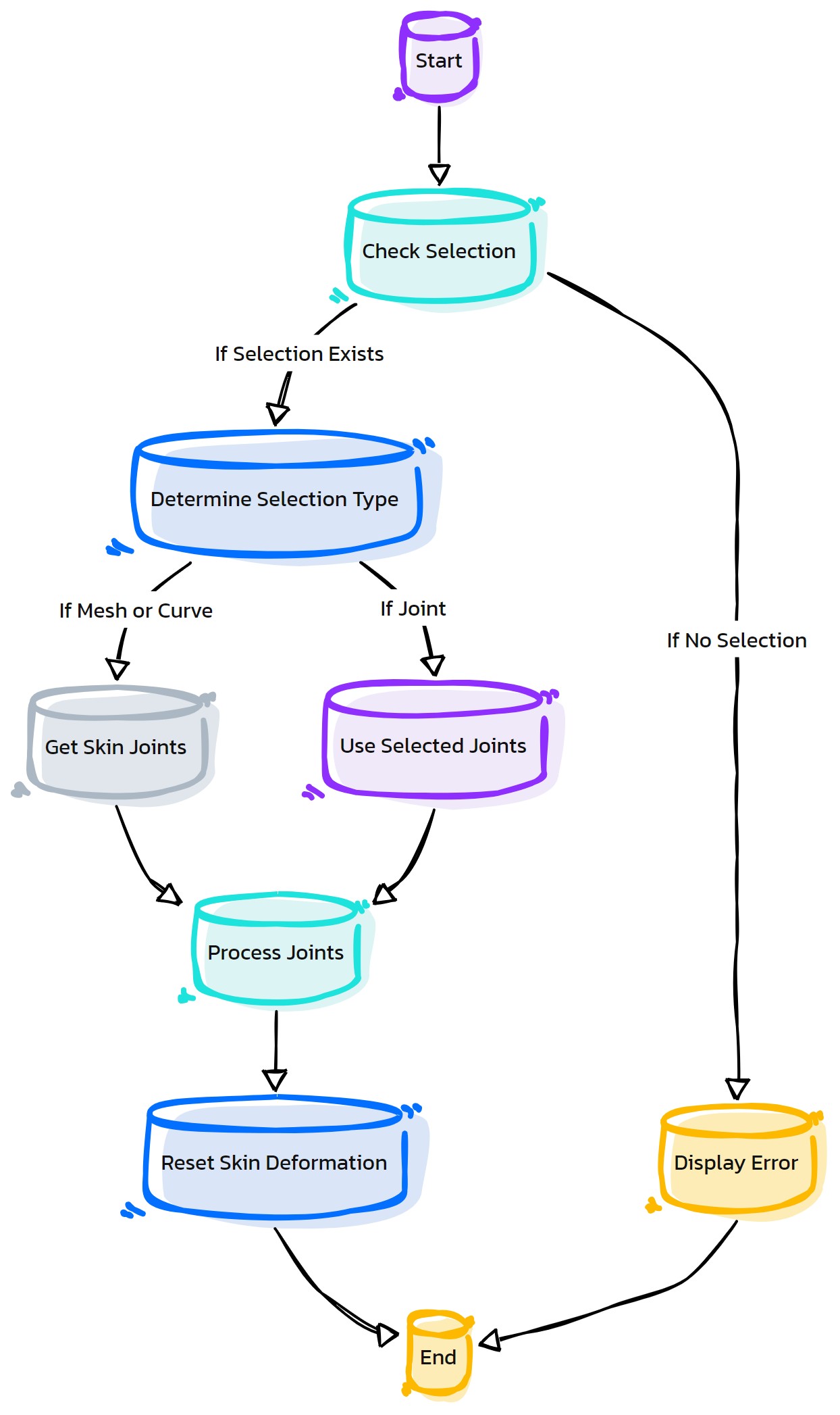
- HyperRig.as_SelectBS(self, selObjs=None, action='', **shArgs)#
[shArgs : so=selObjs, ac=action]
Purpose:
:: Selects or disables blend shapes on selected objects in Maya.
Facilitates quick selection or deactivation of blend shapes for character rigging or animation.
Streamlines the process of managing blend shapes on multiple objects.
Supports disabling all blend shape targets of the selected objects.
- Parameters:
selObjs – <list, optional> # List of objects to select blend shapes on.
action – <str> # Action to perform: ‘disable’ to disable blend shapes.
- Returns:
None # This function does not return a value but affects blend shapes on objects.
Code Examples:
>>> as_SelectBS(selObjs=['object1', 'object2'], action='disable')
# Disables all blend shape targets on the specified objects.
graph TB Start[("fa:fa-play Start")] --> GetSelectedObjects["/fas:fa-mouse-pointer Get Selected Objects"] GetSelectedObjects --> CheckObjectType{"/fas:fa-question-circle Check Object Type"} CheckObjectType --"If Mesh"--> ListBlendShapes["/fas:fa-list-ol List Blend Shapes"] CheckObjectType --"If Transform"--> SelectHierarchy["/fas:fa-sitemap Select Hierarchy"] SelectHierarchy --> ListBlendShapes ListBlendShapes --> CheckAction{"/fas:fa-question-circle Check Action"} CheckAction --"If 'disable'"--> DisableBlendShapes["/fas:fa-ban Disable Blend Shapes"] CheckAction --"If no specific action"--> End[("fas:fa-stop End")] DisableBlendShapes --> RaiseAttributeEditor["/fas:fa-sliders-h Raise Attribute Editor"] RaiseAttributeEditor --> SelectObjects["/fas:fa-mouse-pointer Select Objects"] SelectObjects --> DisplayDisabledInfo["/fas:fa-info-circle Display Disabled Info"] DisplayDisabledInfo --> End style Start fill:#00cc00,stroke:#000,stroke-width:3px style GetSelectedObjects fill:#ffcc00,stroke:#000,stroke-width:2px style CheckObjectType fill:#ff9999,stroke:#000,stroke-width:2px style ListBlendShapes fill:#99ccff,stroke:#000,stroke-width:2px style SelectHierarchy fill:#cc99ff,stroke:#000,stroke-width:2px style CheckAction fill:#99ff99,stroke:#000,stroke-width:2px style DisableBlendShapes fill:#ffcc99,stroke:#000,stroke-width:2px style RaiseAttributeEditor fill:#ccffcc,stroke:#000,stroke-width:2px style SelectObjects fill:#99ccff,stroke:#000,stroke-width:2px style DisplayDisabledInfo fill:#cc99ff,stroke:#000,stroke-width:2px style End fill:#ff6666,stroke:#000,stroke-width:3px- Flow Chart Description:
This flowchart illustrates the as_SelectBS function:
Starts by obtaining a list of selected objects in the Maya scene.
- Checks the type of the selected objects to determine if they are meshes or transforms.
If they are meshes, it lists their blend shapes.
If they are transforms, it selects the entire hierarchy to list blend shapes.
- After listing blend shapes, checks if the action is to ‘disable’.
If the action is ‘disable’, it disables all blend shape targets for the selected objects.
Raises the Attribute Editor or Channel Box to show the changes.
Selects the objects with disabled blend shapes and displays a confirmation message.
- HyperRig.as_SelectByType(self, select_Type=1, nodeSuffix=None, **shArgs)#
[shArgs: ]
Purpose:
:: Selects objects in the scene by a specified type or custom node suffix in Autodesk Maya.
This function streamlines the selection process, especially in complex scenes with numerous object types.
- Parameters:
select_Type – <int> # The type of objects to select (e.g., 1 for controls, 2 for joints).
nodeSuffix – <str> # Optional custom suffix for selecting nodes.
- Returns:
<list> # Returns a list of selected objects of the specified type or with the custom suffix.
Code Examples:
>>> select_type = 1
>>> node_suffix = "Ctrl"
>>> as_SelectByType(select_Type=select_type, nodeSuffix=node_suffix)
# Selects all objects of type 1 (controls) with the specified node suffix.
graph TB Start[("fa:fa-play Start")] --> CheckSelectType{"/fas:fa-question-circle Check Select Type"} CheckSelectType --"Type 1 (Controls)" --> CheckNodeSuffix1{"/fas:fa-search-plus Check Node Suffix for Controls"} CheckNodeSuffix1 --"If Node Suffix Specified" --> SelectControlsWithSuffix[("/fas:fa-mouse-pointer Select Controls With Suffix")] CheckNodeSuffix1 --"If No Node Suffix" --> SelectAllControls[("/fas:fa-mouse-pointer Select All Controls")] CheckSelectType --"Type 2 (Joints)" --> CheckNodeSuffix2{"/fas:fa-search-plus Check Node Suffix for Joints"} CheckNodeSuffix2 --"If Node Suffix Specified" --> SelectJointsWithSuffix[("/fas:fa-mouse-pointer Select Joints With Suffix")] CheckNodeSuffix2 --"If No Node Suffix" --> SelectAllJoints[("/fas:fa-mouse-pointer Select All Joints")] CheckSelectType --"Type 3 (Geometry)" --> CheckNodeSuffix3{"/fas:fa-search-plus Check Node Suffix for Geometry"} CheckNodeSuffix3 --"If Node Suffix Specified" --> SelectGeometryWithSuffix[("/fas:fa-mouse-pointer Select Geometry With Suffix")] CheckNodeSuffix3 --"If No Node Suffix" --> SelectAllGeometry[("/fas:fa-mouse-pointer Select All Geometry")] CheckSelectType --"Type 4 (Locators)" --> CheckNodeSuffix4{"/fas:fa-search-plus Check Node Suffix for Locators"} CheckNodeSuffix4 --"If Node Suffix Specified" --> SelectLocatorsWithSuffix[("/fas:fa-mouse-pointer Select Locators With Suffix")] CheckNodeSuffix4 --"If No Node Suffix" --> SelectAllLocators[("/fas:fa-mouse-pointer Select All Locators")] CheckSelectType --"Type 5 (Others)" --> CheckNodeSuffix5{"/fas:fa-search-plus Check Node Suffix for Others"} CheckNodeSuffix5 --"If Node Suffix Specified" --> SelectOthersWithSuffix[("/fas:fa-mouse-pointer Select Others With Suffix")] CheckNodeSuffix5 --"If No Node Suffix" --> SelectAllOthers[("/fas:fa-mouse-pointer Select All Others")] CheckSelectType --"Type 10 (Invert Selection)" --> InvertSelection[("/fas:fa-exchange-alt Invert Selection")] SelectControlsWithSuffix --> End[("fas:fa-stop-circle End")] SelectAllControls --> End SelectJointsWithSuffix --> End SelectAllJoints --> End SelectGeometryWithSuffix --> End SelectAllGeometry --> End SelectLocatorsWithSuffix --> End SelectAllLocators --> End SelectOthersWithSuffix --> End SelectAllOthers --> End InvertSelection --> End style Start fill:#00cc00,stroke:#000,stroke-width:3px style CheckSelectType fill:#f0ad4e,stroke:#000,stroke-width:2px style CheckNodeSuffix1 fill:#5bc0de,stroke:#000,stroke-width:2px style SelectControlsWithSuffix fill:#5cb85c,stroke:#000,stroke-width:2px style SelectAllControls fill:#5cb85c,stroke:#000,stroke-width:2px style CheckNodeSuffix2 fill:#5bc0de,stroke:#000,stroke-width:2px style SelectJointsWithSuffix fill:#5cb85c,stroke:#000,stroke-width:2px style SelectAllJoints fill:#5cb85c,stroke:#000,stroke-width:2px style CheckNodeSuffix3 fill:#5bc0de,stroke:#000,stroke-width:2px style SelectGeometryWithSuffix fill:#5cb85c,stroke:#000,stroke-width:2px style SelectAllGeometry fill:#5cb85c,stroke:#000,stroke-width:2px style CheckNodeSuffix4 fill:#5bc0de,stroke:#000,stroke-width:2px style SelectLocatorsWithSuffix fill:#5cb85c,stroke:#000,stroke-width:2px style SelectAllLocators fill:#5cb85c,stroke:#000,stroke-width:2px style CheckNodeSuffix5 fill:#5bc0de,stroke:#000,stroke-width:2px style SelectOthersWithSuffix fill:#5cb85c,stroke:#000,stroke-width:2px style SelectAllOthers fill:#5cb85c,stroke:#000,stroke-width:2px style InvertSelection fill:#d9534f,stroke:#000,stroke-width:2px style End fill:#ff6666,stroke:#000,stroke-width:3px- Flow Chart Description:
This flowchart illustrates the as_SelectByType function:
Begins by checking the type of objects to select.
- For each type (controls, joints, geometry, locators, others):
Checks if a custom node suffix is specified.
If a node suffix is specified, selects objects of that type with the suffix.
If no node suffix is specified, selects all objects of that type.
If type 10 is chosen, inverts the current selection.
The process concludes.
- HyperRig.as_SelectHI(self, nodeType=None, noEndJnt=0, typeInput=None, endsWith=None, **shArgs)#
[shArgs : ol=objList, nt=nodeType, ne=noEndJnt, ti=typeInput, ew=endsWith]
Purpose:
:: Selects hierarchy of objects based on node type in Maya.
Ideal for filtering and selecting objects within a hierarchy, such as joints, meshes, etc.
Supports exclusion of end joints in a joint chain.
Allows dynamic input of node types and optional filtering based on name endings.
- Parameters:
objList – <list> # List of objects to begin the hierarchy selection from.
nodeType – <str, optional> # Type of node to filter the selection.
noEndJnt – <int> # Whether to exclude end joints in the selection (1) or not (0).
typeInput – <str, optional> # Dynamic input for node type, if required.
endsWith – <str, optional> # Filter objects that end with a specific string.
- Returns:
None # This function does not return a value but selects objects in the scene.
Code Examples:
>>> as_SelectHI(objList=['rootJoint'], nodeType='jnt', noEndJnt=1)
# Selects all joints in the hierarchy of 'rootJoint', excluding end joints.
graph TB Start[("fa:fa-play Start")] --> GetSelectedObjects["/fas:fa-mouse-pointer Get Selected Objects"] GetSelectedObjects --> CheckNodeType{"/fas:fa-question-circle Check Node Type"} CheckNodeType --"If Node Type Given"--> SelectHierarchy["/fas:fa-sitemap Select Hierarchy"] CheckNodeType --"If No Node Type Given"--> PromptNodeType["/fas:fa-keyboard Prompt Node Type"] PromptNodeType --> SelectHierarchy SelectHierarchy --> FilterEndJoints{"/fas:fa-filter Filter End Joints"} FilterEndJoints --"If No End Joints"--> ExcludeEndJoints["/fas:fa-times-circle Exclude End Joints"] FilterEndJoints --"Include End Joints"--> End[("fas:fa-stop End")] ExcludeEndJoints --> End style Start fill:#00cc00,stroke:#000,stroke-width:3px style GetSelectedObjects fill:#ffcc00,stroke:#000,stroke-width:2px style CheckNodeType fill:#ff9999,stroke:#000,stroke-width:2px style SelectHierarchy fill:#99ccff,stroke:#000,stroke-width:2px style PromptNodeType fill:#cc99ff,stroke:#000,stroke-width:2px style FilterEndJoints fill:#99ff99,stroke:#000,stroke-width:2px style ExcludeEndJoints fill:#ffcc99,stroke:#000,stroke-width:2px style End fill:#ff6666,stroke:#000,stroke-width:3px- Flow Chart Description:
This flowchart illustrates the as_SelectHI function:
Starts by selecting objects based on the user’s input.
- Checks if a specific node type has been provided.
If a node type is given, it selects the entire hierarchy of that node type.
If no node type is given, prompts the user to input the desired node type.
- After selecting the hierarchy, it checks if end joints need to be excluded.
If ‘noEndJnt’ is set, it excludes end joints from the selection.
Completes the process by selecting the filtered hierarchy or excluding end joints.
- HyperRig.as_SelectInvSkinJoints(self, **shArgs)#
[shArgs: ]
Purpose:
:: Selects inverse skin joints that are not part of the current selection in Autodesk Maya.
This function is useful for riggers and animators to quickly select joints that are not currently influencing the skin.
- Returns:
<list> # Returns a list of inverse skin joints not included in the current selection.
Code Examples:
>>> as_SelectInvSkinJoints()
# Selects inverse skin joints not part of the current selection.
graph TB Start[("fa:fa-play Start")] --> CheckSkinMesh[("/fas:fa-cube Check SkinMesh in UI")] CheckSkinMesh --"If SkinMesh is defined" --> GetSkinJoints[("/fas:fa-sitemap Get All Skin Joints")] CheckSkinMesh --"If SkinMesh is not defined" --> Error[("/fas:fa-exclamation-triangle Error: 'SkinMesh' not defined")] GetSkinJoints --> GetCurrentSelection{"/fas:fa-check-circle Get Current Selection"} GetCurrentSelection --"Joints Selected" --> CompareSelection[("/fas:fa-balance-scale Compare Selection with All Joints")] CompareSelection --> SelectInverseJoints[("/fas:fa-hand-point-up Select Inverse Joints")] SelectInverseJoints --"Select joints not in current selection" --> End[("fas:fa-stop-circle End")] style Start fill:#00cc00,stroke:#000,stroke-width:3px style CheckSkinMesh fill:#ffcc00,stroke:#000,stroke-width:2px style Error fill:#d9534f,stroke:#000,stroke-width:2px style GetSkinJoints fill:#5cb85c,stroke:#000,stroke-width:2px style GetCurrentSelection fill:#ffcc00,stroke:#000,stroke-width:2px style CompareSelection fill:#f0ad4e,stroke:#000,stroke-width:2px style SelectInverseJoints fill:#337ab7,stroke:#000,stroke-width:2px style End fill:#ff6666,stroke:#000,stroke-width:3px- Flow Chart Description:
This flowchart illustrates the as_SelectInvSkinJoints function:
The process begins by checking if the ‘SkinMesh’ is defined in the UI.
If ‘SkinMesh’ is not defined, an error message is displayed.
It retrieves all skin joints associated with the ‘SkinMesh’.
The function then gets the current selection of joints.
It compares the current selection with the list of all skin joints.
Finally, it selects the inverse joints, which are not part of the current selection.
- HyperRig.as_SelectSiblings(self, **shArgs)#
[shArgs: ]
Purpose:
:: Selects sibling objects of the currently selected object in Autodesk Maya.
Useful for rigging and scene organization, allowing quick selection of related objects in a hierarchy.
- Returns:
None # This function does not return any value but selects siblings of the current selection.
Code Examples:
>>> as_SelectSiblings()
# Selects sibling objects of the currently selected object.
- HyperRig.as_SetCtrlsHistory(self, selList=None, showHist=0, **shArgs)#
[shArgs: ]
Purpose:
:: Sets the historical interest attribute for selected controls, optimizing scene performance and management.
Ideal for large scenes where controlling the visibility of historical data can enhance performance.
Provides the option to show or hide historical data for selected controls.
- Parameters:
selList – <list, optional> #A list of controls for which the historical interest is to be set. If not provided, uses the current selection.
showHist – <int, optional> #Determines whether to show (1) or hide (0) the historical data. Default is 0.
- Returns:
None # This function does not return any value but sets the historical interest for the selected controls.
Code Examples:
>>> as_SetCtrlsHistory([control1, control2], 1)
# Sets the historical interest for the specified controls to show.
graph TB Start[("fa:fa-play Start")] --> CheckSelection{"/fas:fa-check-circle Check Selection"} CheckSelection --"If selList is provided" --> SetHistAttr{"/fas:fa-history Set Historical Interest"} CheckSelection --"If selList is not provided" --> GetAllNodes{"/fas:fa-sitemap Get All Nodes"} GetAllNodes --> SetHistAttr SetHistAttr --"Set historical interest attribute based on showHist"--> End[("fas:fa-stop End")] style Start fill:#00cc00,stroke:#000,stroke-width:3px style CheckSelection fill:#f0ad4e,stroke:#000,stroke-width:2px style GetAllNodes fill:#5bc0de,stroke:#000,stroke-width:2px style SetHistAttr fill:#5cb85c,stroke:#000,stroke-width:2px style End fill:#ff6666,stroke:#000,stroke-width:3px- Flow Chart Description:
This flowchart illustrates the as_SetCtrlsHistory function:
The process begins by checking if a specific list of controls (selList) is provided.
If selList is not provided, the function gathers all nodes in the scene.
The historical interest attribute is then set for either the selected controls or all nodes, based on the value of showHist.
- HyperRig.as_SetNextSibling(self, pos=None, **shArgs)#
[shArgs: ]
Purpose:
:: Sets the next sibling for a selected object in a hierarchy in Autodesk Maya.
Ideal for rigging and scene organization, allowing users to re-order objects in a hierarchical structure.
- Parameters:
pos – <int/None> # Position for the sibling. None for next position, 0 for first, -1 for last.
- Returns:
None # This function does not return any value but sets the next sibling in the hierarchy.
Code Examples:
>>> as_SetNextSibling(pos=None)
# Sets the next sibling for the selected object in its hierarchical order.
graph TB Start[("fa:fa-play Start")] --> CheckSelection{"/fas:fa-question-circle Check Selection"} CheckSelection --"If Selection Exists"--> CheckMultipleSelection{"/fas:fa-question-circle Check Multiple Selection"} CheckSelection --"If No Selection"--> ErrorNoSelection["/fas:fa-exclamation-triangle Error: No Selection"] CheckMultipleSelection --"If Multiple Objects Selected"--> CheckPosValue{"/fas:fa-search-plus Check Position Value"} CheckMultipleSelection --"If Single Object Selected"--> SetSiblingSingle[("/fas:fa-arrow-right Set Sibling for Single Object")] CheckPosValue --"If Position Specified (0, -1)"--> SetSiblingSpecific[("/fas:fa-arrow-right Set Sibling at Specific Position")] CheckPosValue --"If Position Not Specified (None)"--> SetSiblingNext[("/fas:fa-arrow-right Set Next Sibling")] SetSiblingSingle --> End[("fas:fa-stop-circle End")] SetSiblingSpecific --> End SetSiblingNext --> End ErrorNoSelection --> End style Start fill:#00cc00,stroke:#000,stroke-width:3px style CheckSelection fill:#f0ad4e,stroke:#000,stroke-width:2px style CheckMultipleSelection fill:#5bc0de,stroke:#000,stroke-width:2px style CheckPosValue fill:#5cb85c,stroke:#000,stroke-width:2px style SetSiblingSingle fill:#ffcc99,stroke:#000,stroke-width:2px style SetSiblingSpecific fill:#99ccff,stroke:#000,stroke-width:2px style SetSiblingNext fill:#cc99ff,stroke:#000,stroke-width:2px style ErrorNoSelection fill:#d9534f,stroke:#000,stroke-width:2px style End fill:#ff6666,stroke:#000,stroke-width:3px- Flow Chart Description:
This flowchart illustrates the as_SetNextSibling function:
Begins by checking if any object is selected.
If no object is selected, an error is displayed.
- If an object is selected:
Checks if multiple objects are selected.
If multiple objects are selected, checks the position value (0, -1, None).
For specific position values (0, -1), sets siblings at the specific position.
If position is None, sets the next sibling in the hierarchy.
If a single object is selected, sets sibling based on the number of children in the parent.
The process concludes.
- HyperRig.as_SkinPaint(self, val=0.01, operation='add', **shArgs)#
[shArgs: ]
Purpose:
:: Adjusts the skin weight painting tool settings for selected vertices in Autodesk Maya.
This function allows users to modify the behavior and values of the skin weight painting tool.
- Parameters:
val – <float> # The value to set for the paint operation.
operation – <str> # The operation to perform: ‘add’ or ‘scale’.
- Returns:
None # This function does not return any value but adjusts the painting tool settings for the current selection.
Code Examples:
>>> value = 0.01
>>> operation = "add"
>>> as_SkinPaint(value, operation)
# Adjusts the skin weight painting tool settings for the current selection.
graph TB Start[("fa:fa-play Start")] --> GetSelection[("/fas:fa-check-circle Get Current Selection")] GetSelection --> CheckOperation{"/fas:fa-question-circle Check Operation Type"} CheckOperation --"If 'add'" --> SetAdd[("/fas:fa-plus Set 'Add' Operation")] SetAdd --> SetAddOpacity[("/fas:fa-adjust Set Opacity for 'Add'")] SetAddOpacity --> SetAddValue[("/fas:fa-pencil-alt Set Value for 'Add'")] CheckOperation --"If 'scale'" --> SetScale[("/fas:fa-balance-scale Set 'Scale' Operation")] SetScale --> SetScaleOpacity[("/fas:fa-adjust Set Opacity for 'Scale'")] SetScaleOpacity --> SetScaleValue[("/fas:fa-pencil-alt Set Value for 'Scale'")] SetAddValue --> CheckVertex[("/fas:fa-code-branch Check if Selection is Vertex")] SetScaleValue --> CheckVertex CheckVertex --"If Selected is Vertex" --> SelectVertices[("/fas:fa-object-group Select Vertices")] SelectVertices --> End[("fas:fa-stop-circle End")] CheckVertex --"If Selected is Not Vertex" --> End style Start fill:#00cc00,stroke:#000,stroke-width:3px style GetSelection fill:#ffcc00,stroke:#000,stroke-width:2px style CheckOperation fill:#f0ad4e,stroke:#000,stroke-width:2px style SetAdd fill:#5bc0de,stroke:#000,stroke-width:2px style SetAddOpacity fill:#5bc0de,stroke:#000,stroke-width:2px style SetAddValue fill:#5bc0de,stroke:#000,stroke-width:2px style SetScale fill:#5bc0de,stroke:#000,stroke-width:2px style SetScaleOpacity fill:#5bc0de,stroke:#000,stroke-width:2px style SetScaleValue fill:#5bc0de,stroke:#000,stroke-width:2px style CheckVertex fill:#ffcc00,stroke:#000,stroke-width:2px style SelectVertices fill:#5cb85c,stroke:#000,stroke-width:2px style End fill:#ff6666,stroke:#000,stroke-width:3px- Flow Chart Description:
This flowchart illustrates the as_SkinPaint function:
The process starts by getting the current selection.
It checks the operation type, which can be either ‘add’ or ‘scale’.
For the ‘add’ operation, it sets the operation, opacity, and value.
For the ‘scale’ operation, it also sets the operation, opacity, and value.
The function then checks if the selection is a vertex.
If the selection is a vertex, it selects the vertices and adjusts the painting tool settings.
- HyperRig.as_SkinPaint_SelectedJoints(self, val=0.01, operation='add', **shArgs)#
[shArgs: ]
Purpose:
:: Adjusts skin weights for selected joints and vertices in Autodesk Maya.
This function is similar to as_SkinPaint but specifically targets selected joints and vertices for weight painting.
- Parameters:
val – <float> # The value to set for the paint operation.
operation – <str> # The operation to perform: ‘add’ or ‘scale’.
- Returns:
None # This function does not return any value but adjusts skin weights for selected joints and vertices.
Code Examples:
>>> value = 0.01
>>> operation = "add"
>>> as_SkinPaint_SelectedJoints(value, operation)
# Adjusts skin weights for selected joints and vertices.
graph TB Start[("fa:fa-play Start")] --> GetSelection[("/fas:fa-check-circle Get Current Selection")] GetSelection --> ExtractJointsAndVertices[("/fas:fa-filter Extract Joints and Vertices")] ExtractJointsAndVertices --> CheckOperation{"/fas:fa-question-circle Check Operation Type"} CheckOperation --"If 'add'" --> SetAdd[("/fas:fa-plus Set 'Add' Operation")] SetAdd --> SetAddOpacity[("/fas:fa-adjust Set Opacity for 'Add'")] SetAddOpacity --> SetAddValue[("/fas:fa-pencil-alt Set Value for 'Add'")] CheckOperation --"If 'scale'" --> SetScale[("/fas:fa-balance-scale Set 'Scale' Operation")] SetScale --> SetScaleOpacity[("/fas:fa-adjust Set Opacity for 'Scale'")] SetScaleOpacity --> SetScaleValue[("/fas:fa-pencil-alt Set Value for 'Scale'")] SetAddValue --> StartProgress[("/fas:fa-spinner Start Progress Bar for Joints")] SetScaleValue --> StartProgress StartProgress --> ApplyToEachJoint[("/fas:fa-paint-brush Apply Settings to Each Joint")] ApplyToEachJoint --> EndProgress[("/fas:fa-check-square End Progress Bar")] EndProgress --> End[("fas:fa-stop-circle End")] style Start fill:#00cc00,stroke:#000,stroke-width:3px style GetSelection fill:#ffcc00,stroke:#000,stroke-width:2px style ExtractJointsAndVertices fill:#f0ad4e,stroke:#000,stroke-width:2px style CheckOperation fill:#ffcc00,stroke:#000,stroke-width:2px style SetAdd fill:#5bc0de,stroke:#000,stroke-width:2px style SetAddOpacity fill:#5bc0de,stroke:#000,stroke-width:2px style SetAddValue fill:#5bc0de,stroke:#000,stroke-width:2px style SetScale fill:#5bc0de,stroke:#000,stroke-width:2px style SetScaleOpacity fill:#5bc0de,stroke:#000,stroke-width:2px style SetScaleValue fill:#5bc0de,stroke:#000,stroke-width:2px style StartProgress fill:#5cb85c,stroke:#000,stroke-width:2px style ApplyToEachJoint fill:#5cb85c,stroke:#000,stroke-width:2px style EndProgress fill:#5cb85c,stroke:#000,stroke-width:2px style End fill:#ff6666,stroke:#000,stroke-width:3px- Flow Chart Description:
This flowchart illustrates the as_SkinPaint_SelectedJoints function:
The process begins by obtaining the current selection of joints and vertices.
It then checks the operation type, either ‘add’ or ‘scale’.
For the ‘add’ operation, it sets the operation type, opacity, and value.
For the ‘scale’ operation, it also sets the operation type, opacity, and value.
A progress bar is started for each joint in the selection.
The settings are applied to each joint in the selection.
Finally, the progress bar is ended, and the process is completed.
- HyperRig.as_SmoothNearest(self, **shArgs)#
[shArgs: ]
Purpose:
:: Executes the as_SmoothNearestMain function in Autodesk Maya.
This function is used for smoothing operations, related to skin weights or geometry.
- Returns:
None # This function does not return any value but triggers the as_SmoothNearestMain function.
Code Examples:
>>> as_SmoothNearest()
# Executes the as_SmoothNearestMain function.
graph TB Start[("fa:fa-play Start")] --> ExecuteSmoothNearest[("/fas:fa-smooth Execute as_SmoothNearestMain")] ExecuteSmoothNearest --> End[("fas:fa-stop End")] style Start fill:#00cc00,stroke:#000,stroke-width:3px style ExecuteSmoothNearest fill:#ff9999,stroke:#000,stroke-width:2px style End fill:#ff6666,stroke:#000,stroke-width:3px- Flow Chart Description:
This flowchart illustrates the as_SmoothNearest function:
The process begins by executing the as_SmoothNearestMain function in Autodesk Maya.
The function is used for smoothing operations, such as skin weights or geometry adjustments.
- HyperRig.as_SnapCtrlShapes(self, **shArgs)#
[shArgs: ]
Purpose:
:: Snaps control shapes to their respective controls in Autodesk Maya.
Essential for rigging to ensure control shapes are correctly aligned with their respective controls.
- Returns:
None # This function does not return any value but snaps control shapes to their controls.
Code Examples:
>>> as_SnapCtrlShapes()
# Snaps control shapes to their respective controls.
graph TB Start[("fa:fa-play Start")] --> CheckSelection{"/fas:fa-question-circle Check Selection"} CheckSelection --"If Selection Exists"--> RetrieveControls[("/fas:fa-sitemap Retrieve Controls")] CheckSelection --"If No Selection"--> ErrorNoSelection["/fas:fa-exclamation-triangle Error: No Selection"] RetrieveControls --> CheckShapeType{"/fas:fa-question-circle Check Shape Type"} CheckShapeType --"If Control Is Curve"--> SnapShapes[("/fas:fa-arrows-alt Snap Shapes To Controls")] CheckShapeType --"If Not Curve"--> SkipControl["/fas:fa-forward Skip Control"] SnapShapes --> NextControl{"/fas:fa-arrow-right Next Control"} SkipControl --> NextControl NextControl --"Next Control"--> CheckShapeType NextControl --"All Controls Processed"--> End[("fas:fa-stop-circle End")] ErrorNoSelection --> End style Start fill:#00cc00,stroke:#000,stroke-width:3px style CheckSelection fill:#f0ad4e,stroke:#000,stroke-width:2px style RetrieveControls fill:#5bc0de,stroke:#000,stroke-width:2px style CheckShapeType fill:#5cb85c,stroke:#000,stroke-width:2px style SnapShapes fill:#ffcc99,stroke:#000,stroke-width:2px style SkipControl fill:#d9534f,stroke:#000,stroke-width:2px style NextControl fill:#f0ad4e,stroke:#000,stroke-width:2px style End fill:#ff6666,stroke:#000,stroke-width:3px- Flow Chart Description:
This flowchart illustrates the as_SnapCtrlShapes function:
The process starts by checking if an object is selected.
If no object is selected, an error message is displayed.
If an object is selected, it retrieves the list of selected controls.
- For each control:
Checks if the control is a curve.
If the control is a curve, snaps the control shape to the control.
If the control is not a curve, it skips to the next control.
Continues the process for all selected controls.
The process concludes.
- HyperRig.as_SnapPivTo(self, snapToOrigin=0, **shArgs)#
[shArgs: ]
Purpose:
:: Snaps the pivot of selected objects to a target object or to the origin in Autodesk Maya.
Useful in modeling and rigging for precise alignment of object pivots.
- Parameters:
snapToOrigin – <bool> # If True, snaps the pivot to the origin.
- Returns:
None # This function does not return any value but snaps the pivot of selected objects.
Code Examples:
>>> snap_to_origin = False
>>> as_SnapPivTo(snapToOrigin=snap_to_origin)
# Snaps the pivot of selected objects to the last selected object.
graph TB Start[("fa:fa-play Start")] --> CheckSelection{"/fas:fa-question-circle Check Selection"} CheckSelection --"If Selection Exists"--> IterateObjects[("/fas:fa-clipboard-list Iterate Objects")] CheckSelection --"If No Selection"--> ErrorNoSelection["/fas:fa-exclamation-triangle Error: No Selection"] IterateObjects --> CheckSnapToOrigin{"/fas:fa-question-circle Check Snap to Origin"} CheckSnapToOrigin --"If Snap To Origin"--> SnapToOrigin[("/fas:fa-crosshairs Snap Pivot to Origin")] CheckSnapToOrigin --"If Not Snap To Origin"--> SnapToLastSelected[("/fas:fa-arrows-alt Snap Pivot to Last Selected")] SnapToOrigin --> NextObject{"/fas:fa-arrow-right Next Object"} SnapToLastSelected --> NextObject NextObject --"Next Object"--> IterateObjects NextObject --"All Objects Processed"--> End[("fas:fa-stop-circle End")] ErrorNoSelection --> End style Start fill:#00cc00,stroke:#000,stroke-width:3px style CheckSelection fill:#f0ad4e,stroke:#000,stroke-width:2px style IterateObjects fill:#5bc0de,stroke:#000,stroke-width:2px style CheckSnapToOrigin fill:#5cb85c,stroke:#000,stroke-width:2px style SnapToOrigin fill:#ffcc99,stroke:#000,stroke-width:2px style SnapToLastSelected fill:#d9534f,stroke:#000,stroke-width:2px style NextObject fill:#f0ad4e,stroke:#000,stroke-width:2px style End fill:#ff6666,stroke:#000,stroke-width:3px- Flow Chart Description:
This flowchart illustrates the as_SnapPivTo function:
Starts by checking if objects are selected.
If no objects are selected, an error message is displayed.
If objects are selected, it iterates through each object (except the last one).
- Checks if the pivot should be snapped to the origin.
If yes, snaps the pivot of the object to the origin [0, 0, 0].
If no, snaps the pivot of the object to the position of the last selected object.
Continues the process for all selected objects (except the last one).
The process concludes.
- HyperRig.as_SnapPosTo(self, snapRot=0, nearCenter=0, **shArgs)#
[shArgs: ]
Purpose:
:: Snaps the position of selected objects to a target object or nearest center in Autodesk Maya.
This function is used in rigging and modeling to precisely align objects based on their positions.
- Parameters:
snapRot – <bool> # Determines if rotation should also be snapped.
nearCenter – <bool> # If True, snaps to the nearest center between multiple selected objects.
- Returns:
None # This function does not return any value but snaps positions of selected objects to the target or nearest center.
Code Examples:
>>> snap_rotation = True
>>> snap_to_nearest_center = False
>>> as_SnapPosTo(snap_rotation, snap_to_nearest_center)
# Snaps the position (and rotation if specified) of selected objects to the target or nearest center.
graph TB Start[("fa:fa-play Start")] --> CheckSelection{"/fas:fa-check-circle Check Selection"} CheckSelection --"If no selection" --> ErrorNoSelection["/fas:fa-exclamation-triangle Error: No Selection"] CheckSelection --"If selection is present" --> CheckNearCenter{"/fas:fa-question-circle Check nearCenter"} CheckNearCenter --"If nearCenter is True" --> CheckSelectionCount{"/fas:fa-sort-amount-up Check Selection Count"} CheckNearCenter --"If nearCenter is False" --> SnapPositions["/fas:fa-arrows-alt Snap Positions"] CheckSelectionCount --"If selection count != 3" --> CheckJointSelection{"/fas:fa-bone Check Joint Selection"} CheckSelectionCount --"If selection count is 3" --> GenerateCurve["/fas:fa-bezier-curve Generate Curve"] CheckJointSelection --"If joint with parent and child" --> UpdateSelectionList["/fas:fa-list-ul Update Selection List"] CheckJointSelection --"If not a joint or no parent/child" --> ErrorInvalidJointSelection["/fas:fa-exclamation-triangle Error: Invalid Joint Selection"] UpdateSelectionList --> GenerateCurve GenerateCurve --> LocateClosestPosition["/fas:fa-map-marker-alt Locate Closest Position"] LocateClosestPosition --> SnapToClosestPosition["/fas:fa-compress-arrows-alt Snap to Closest Position"] SnapToClosestPosition --> DeleteTempObjects["/fas:fa-trash-alt Delete Temporary Objects"] SnapPositions --> End[("fas:fa-stop End")] ErrorNoSelection --> End ErrorInvalidJointSelection --> End DeleteTempObjects --> End style Start fill:#00cc00,stroke:#000,stroke-width:3px style CheckSelection fill:#ffcc00,stroke:#000,stroke-width:2px style ErrorNoSelection fill:#ff6666,stroke:#000,stroke-width:2px style CheckNearCenter fill:#ffcc00,stroke:#000,stroke-width:2px style CheckSelectionCount fill:#ffcc00,stroke:#000,stroke-width:2px style CheckJointSelection fill:#ffcc00,stroke:#000,stroke-width:2px style UpdateSelectionList fill:#ff9999,stroke:#000,stroke-width:2px style GenerateCurve fill:#ff9999,stroke:#000,stroke-width:2px style LocateClosestPosition fill:#ff9999,stroke:#000,stroke-width:2px style SnapToClosestPosition fill:#ff9999,stroke:#000,stroke-width:2px style DeleteTempObjects fill:#ff9999,stroke:#000,stroke-width:2px style SnapPositions fill:#ff9999,stroke:#000,stroke-width:2px style ErrorInvalidJointSelection fill:#ff6666,stroke:#000,stroke-width:2px style End fill:#ff6666,stroke:#000,stroke-width:3px- Flow Chart Description:
This flowchart illustrates the as_SnapPosTo function:
The function starts by checking the selection of objects. If no objects are selected, an error is displayed.
If nearCenter is True, it checks the number of selected objects. If the count is not three, it further checks if the selected object is a joint with a parent and child.
If the selected joint is valid, the selection list is updated. A temporary curve is generated to locate the closest position to snap.
The source object is then snapped to this closest position, and temporary objects are deleted.
If nearCenter is False, the positions of the selected objects are directly snapped to the last selected object.
- HyperRig.as_SnapRotTo(self, toWorld=0, mirrBehaviour=0, **shArgs)#
[shArgs: ]
Purpose:
:: Snaps the rotation of selected objects to a target object or aligns to the world axis in Autodesk Maya.
Useful in rigging and animation for aligning rotations of objects or controls.
- Parameters:
toWorld – <bool> # If True, aligns the rotation to the world axis.
mirrBehaviour – <bool> # If True, mirrors the rotation behavior for the selected objects.
- Returns:
None # This function does not return any value but snaps the rotation of selected objects.
Code Examples:
>>> as_SnapRotTo(toWorld=True, mirrBehaviour=False)
# Snaps the rotation of selected objects to the world axis without mirroring behavior.
graph TB Start[("fa:fa-play Start")] --> CheckSelection{"/fas:fa-check-circle Check Selection"} CheckSelection --"If no selection" --> ErrorNoSelection["/fas:fa-exclamation-triangle Error: No Selection"] CheckSelection --"If selection is present" --> CheckMirrorBehaviour{"/fas:fa-question-circle Check mirrBehaviour"} CheckMirrorBehaviour --"If mirrBehaviour is True" --> CheckSelectionCount{"/fas:fa-sort-amount-up Check Selection Count"} CheckMirrorBehaviour --"If mirrBehaviour is False" --> CheckToWorld{"/fas:fa-globe-americas Check toWorld"} CheckSelectionCount --"If selection count is 2" --> SnapMirrorBehaviour["/fas:fa-exchange-alt Snap with Mirror Behaviour"] CheckSelectionCount --"If selection count is 1" --> AdjustAndSnapMirror["/fas:fa-object-group Adjust and Snap with Mirror"] SnapMirrorBehaviour --> End[("fas:fa-stop End")] AdjustAndSnapMirror --> End CheckToWorld --"If toWorld is True" --> SnapToWorldAxis["/fas:fa-compass Snap to World Axis"] CheckToWorld --"If toWorld is False" --> SnapRotations["/fas:fa-sync-alt Snap Rotations"] SnapToWorldAxis --> End SnapRotations --> End ErrorNoSelection --> End style Start fill:#00cc00,stroke:#000,stroke-width:3px style CheckSelection fill:#ffcc00,stroke:#000,stroke-width:2px style ErrorNoSelection fill:#ff6666,stroke:#000,stroke-width:2px style CheckMirrorBehaviour fill:#ffcc00,stroke:#000,stroke-width:2px style CheckSelectionCount fill:#ffcc00,stroke:#000,stroke-width:2px style SnapMirrorBehaviour fill:#ff9999,stroke:#000,stroke-width:2px style AdjustAndSnapMirror fill:#ff9999,stroke:#000,stroke-width:2px style CheckToWorld fill:#ffcc00,stroke:#000,stroke-width:2px style SnapToWorldAxis fill:#ff9999,stroke:#000,stroke-width:2px style SnapRotations fill:#ff9999,stroke:#000,stroke-width:2px style End fill:#ff6666,stroke:#000,stroke-width:3px- Flow Chart Description:
This flowchart illustrates the as_SnapRotTo function:
The function begins by checking if any objects are selected. If not, an error is displayed.
It then checks if the mirrBehaviour parameter is True. If so, it further checks the selection count.
For two selected objects, it snaps the rotation with mirror behavior. For one object, it adjusts and snaps with mirror behavior.
If mirrBehaviour is False, it checks if toWorld is True to snap the rotation to the world axis.
If toWorld is False, it snaps the rotations of the selected objects to the last selected object.
- HyperRig.as_SnapToComponents(self, components='vtx', **shArgs)#
[shArgs: ]
Purpose:
:: Snaps selected objects to specified components (vertices or edges) in Autodesk Maya.
This function is primarily used in modeling and rigging for precise positioning of objects relative to mesh components.
- Parameters:
components – <str> # Specifies the type of components to snap to, such as ‘vtx’ for vertices or ‘edge’ for edges.
- Returns:
None # This function does not return any value but snaps objects to the specified components.
Code Examples:
>>> as_SnapToComponents(components='vtx')
# Snaps selected objects to vertices of a mesh.
graph TB Start[("fa:fa-play Start")] --> CheckSelection{"/fas:fa-check-circle Check Selection"} CheckSelection --"If selection is present" --> CheckComponents{"/fas:fa-object-ungroup Check Components"} CheckSelection --"If no selection" --> ErrorNoSelection["/fas:fa-exclamation-triangle Error: No Selection"] CheckComponents --"If 'vtx'" --> FilterVertices["/fas:fa-th Filter Vertices"] CheckComponents --"If 'edge'" --> FilterEdges["/fas:fa-edge Filter Edges"] FilterVertices --> SnapToVertices["/fas:fa-map-marker-alt Snap to Vertices"] FilterEdges --> SnapToEdges["/fas:fa-map-signs Snap to Edges"] SnapToVertices --> End[("fas:fa-stop End")] SnapToEdges --> End ErrorNoSelection --> End style Start fill:#00cc00,stroke:#000,stroke-width:3px style CheckSelection fill:#ffcc00,stroke:#000,stroke-width:2px style ErrorNoSelection fill:#ff6666,stroke:#000,stroke-width:2px style CheckComponents fill:#ffcc00,stroke:#000,stroke-width:2px style FilterVertices fill:#99ccff,stroke:#000,stroke-width:2px style FilterEdges fill:#99ccff,stroke:#000,stroke-width:2px style SnapToVertices fill:#ff9999,stroke:#000,stroke-width:2px style SnapToEdges fill:#ff9999,stroke:#000,stroke-width:2px style End fill:#ff6666,stroke:#000,stroke-width:3px- Flow Chart Description:
This flowchart illustrates the as_SnapToComponents function:
The process begins by checking if any objects are selected. If not, an error is displayed.
It then checks the components parameter to determine whether to snap to vertices (‘vtx’) or edges.
If ‘vtx’ is chosen, it filters out vertices from the selection and snaps the remaining objects to these vertices.
If ‘edge’ is chosen, it filters out edges from the selection and snaps the remaining objects to these edges.
- HyperRig.as_SnapToPosLocators(self, snapRot=1, snapPos=1, pivotSnap=0, toShapePos=0, **shArgs)#
[shArgs : ol=objList, sr=snapRot, sp=snapPos, ps=pivotSnap, ts=toShapePos]
Purpose:
:: Snaps selected objects to their corresponding position locators in Maya.
Ideal for repositioning objects back to saved locator positions.
Provides options for snapping rotation, position, and pivot.
Can snap to the position of the object’s shape instead of the locator.
- Parameters:
objList – <list> # List of objects to be snapped to their position locators.
snapRot – <int> # Whether to snap the object’s rotation (1) or not (0).
snapPos – <int> # Whether to snap the object’s position (1) or not (0).
pivotSnap – <int> # Whether to snap the object’s pivot to the locator’s position (1) or not (0).
toShapePos – <int> # Whether to snap to the object’s shape position (1) or the locator’s position (0).
- Returns:
None # This function does not return a value but snaps objects to their locators.
Code Examples:
>>> as_SnapToPosLocators(snapRot=1, snapPos=1, pivotSnap=0, toShapePos=0)
# Snaps selected objects to their position locators, including rotation and position.
graph TB Start[("fa:fa-play Start")] --> GetSelectedObjects["/fas:fa-mouse-pointer Get Selected Objects"] GetSelectedObjects --> CheckEachObject{"/fas:fa-question-circle Check Each Object"} CheckEachObject --"For Each Object"--> CheckToShapePos{{"/fas:fa-question-circle Check ToShapePos"}} CheckToShapePos --"If ToShapePos is 1"--> SnapToShapePosition["/fas:fa-arrows-alt Snap To Shape Position"] SnapToShapePosition --> End[("fas:fa-stop End")] CheckToShapePos --"If ToShapePos is 0"--> CheckLocatorExists{"/fas:fa-question-circle Check Locator Exists"} CheckLocatorExists --"If Locator Exists"--> SnapObject{"/fas:fa-exchange-alt Snap Object"} CheckLocatorExists --"If Locator Does Not Exist"--> AddToMissingList["/fas:fa-exclamation-triangle Add to Missing List"] AddToMissingList --> CheckMissingList{"/fas:fa-question-circle Check Missing List"} CheckMissingList --"If Missing List is Not Empty"--> ErrorMissingObjects["/fas:fa-exclamation-triangle Error: Missing Objects"] CheckMissingList --"If Missing List is Empty"--> SelectSnappedObjects["/fas:fa-mouse-pointer Select Snapped Objects"] SnapObject --"Snap Object Based on Settings"--> End ErrorMissingObjects --> End SelectSnappedObjects --> End style Start fill:#00cc00,stroke:#000,stroke-width:3px style GetSelectedObjects fill:#ffcc00,stroke:#000,stroke-width:2px style CheckEachObject fill:#ff9999,stroke:#000,stroke-width:2px style CheckToShapePos fill:#99ccff,stroke:#000,stroke-width:2px style SnapToShapePosition fill:#cc99ff,stroke:#000,stroke-width:2px style CheckLocatorExists fill:#99ff99,stroke:#000,stroke-width:2px style SnapObject fill:#ffcc99,stroke:#000,stroke-width:2px style AddToMissingList fill:#ccffcc,stroke:#000,stroke-width:2px style CheckMissingList fill:#ff9999,stroke:#000,stroke-width:2px style ErrorMissingObjects fill:#99ccff,stroke:#000,stroke-width:2px style SelectSnappedObjects fill:#cc99ff,stroke:#000,stroke-width:2px style End fill:#ff6666,stroke:#000,stroke-width:3px- Flow Chart Description:
This flowchart illustrates the as_SnapToPosLocators function:
Begins by obtaining a list of selected objects in the scene.
For each object, checks if it should snap to the shape position.
If toShapePos is set, the object’s pivot is snapped to its shape position.
If not, checks if a corresponding position locator exists.
If the locator exists, the object is snapped based on the provided settings (position, rotation, pivot snap).
If the locator does not exist, the object is added to a missing list.
At the end, checks if there are any objects in the missing list.
If there are missing objects, an error message is displayed and those objects are selected.
If all objects are successfully snapped, the snapped objects are selected.
- HyperRig.as_SuffixHI(self, selectedObjs=False, **shArgs)#
[shArgs : ol=objList, so=selectedObjs]
Purpose:
:: Adds a specified suffix to the hierarchy of selected objects in Maya.
Useful for organizing and categorizing objects in a scene based on their roles.
Facilitates bulk renaming for rigging or scene management purposes.
Allows for suffix customization to suit different naming conventions.
- Parameters:
objList – <list> # List of objects to append the suffix to.
selectedObjs – <bool, optional> # Whether to only append the suffix to selected objects in the hierarchy (True) or the entire hierarchy (False).
- Returns:
None # This function does not return a value but renames objects in the scene.
Code Examples:
>>> as_SuffixHI(objList=['obj1', 'obj2'], selectedObjs=True)
# Appends the specified suffix to the selected objects in the hierarchy.
graph TB Start[("fa:fa-play Start")] --> GetSelectedObjects["/fas:fa-mouse-pointer Get Selected Objects"] GetSelectedObjects --> CheckFirstObject{"/fas:fa-question-circle Check First Object"} CheckFirstObject --"If First Object is Joint"--> PromptSuffixJnt["/fas:fa-text-height Prompt Suffix (_Jnt)"] CheckFirstObject --"If First Object is Not Joint"--> PromptSuffixGrp["/fas:fa-text-height Prompt Suffix (_Grp)"] PromptSuffixJnt --> CheckPromptResult{"/fas:fa-question-circle Check Prompt Result"} PromptSuffixGrp --> CheckPromptResult CheckPromptResult --"If OK is Clicked"--> GetSuffixText["/fas:fa-pencil-alt Get Suffix Text"] GetSuffixText --> AppendSuffix{"/fas:fa-plus Append Suffix"} CheckPromptResult --"If Cancelled"--> ErrorActionCancelled["/fas:fa-exclamation-triangle Error: Action Cancelled"] AppendSuffix --"Append Suffix to Hierarchy"--> End[("fas:fa-stop End")] ErrorActionCancelled --> End style Start fill:#00cc00,stroke:#000,stroke-width:3px style GetSelectedObjects fill:#ffcc00,stroke:#000,stroke-width:2px style CheckFirstObject fill:#ff9999,stroke:#000,stroke-width:2px style PromptSuffixJnt fill:#99ccff,stroke:#000,stroke-width:2px style PromptSuffixGrp fill:#cc99ff,stroke:#000,stroke-width:2px style CheckPromptResult fill:#99ff99,stroke:#000,stroke-width:2px style GetSuffixText fill:#ffcc99,stroke:#000,stroke-width:2px style AppendSuffix fill:#ccffcc,stroke:#000,stroke-width:2px style ErrorActionCancelled fill:#ff9999,stroke:#000,stroke-width:2px style End fill:#ff6666,stroke:#000,stroke-width:3px- Flow Chart Description:
This flowchart illustrates the as_SuffixHI function:
Starts by obtaining a list of selected objects in the scene.
- Checks the type of the first object in the list.
If it’s a joint, prompts for a suffix with a default of ‘_Jnt’.
If it’s not a joint, prompts for a suffix with a default of ‘_Grp’.
- Checks the user’s response to the prompt.
If ‘OK’ is clicked, retrieves the entered suffix text.
If the action is cancelled, displays an error message and stops.
Appends the entered suffix to each object in the hierarchy based on the selected objects setting.
- HyperRig.as_ToggleCurvVis(self, **shArgs)#
[shArgs: ]
Purpose:
:: Toggles the visibility of NURBS curves in the current viewport in Autodesk Maya.
Useful for animators and riggers to quickly show or hide control curves in the viewport.
- Returns:
None # This function does not return any value but toggles the visibility of NURBS curves.
Code Examples:
>>> as_ToggleCurvVis()
# Toggles the visibility of NURBS curves in the current viewport.
graph TB Start[("fa:fa-play Start")] --> CheckPanel{"/fas:fa-desktop Check Focused Panel"} CheckPanel --"If a panel is focused" --> CheckCurvesVisibility{"/fas:fa-eye-slash Check Curves Visibility"} CheckPanel --"If no panel focused" --> ErrorNoPanel["/fas:fa-exclamation-triangle Error: No Panel Focused"] CheckCurvesVisibility --"If curves visible" --> HideCurves["/fas:fa-eye-slash Hide Curves"] CheckCurvesVisibility --"If curves not visible" --> ShowCurves["/fas:fa-eye Show Curves"] HideCurves --> End[("fas:fa-stop End")] ShowCurves --> End ErrorNoPanel --> End style Start fill:#00cc00,stroke:#000,stroke-width:3px style CheckPanel fill:#ffcc00,stroke:#000,stroke-width:2px style ErrorNoPanel fill:#ff6666,stroke:#000,stroke-width:2px style CheckCurvesVisibility fill:#ffcc00,stroke:#000,stroke-width:2px style HideCurves fill:#ff9999,stroke:#000,stroke-width:2px style ShowCurves fill:#ff9999,stroke:#000,stroke-width:2px style End fill:#ff6666,stroke:#000,stroke-width:3px- Flow Chart Description:
This flowchart illustrates the as_ToggleCurvVis function:
The process starts by checking the currently focused panel in Autodesk Maya.
If a panel is focused, the function checks the visibility state of NURBS curves in that panel.
Depending on the current state, it either hides or shows the NURBS curves in the focused panel.
If no panel is focused, an error is displayed.
- HyperRig.as_ToggleDeformerVis(self, **shArgs)#
[shArgs: ]
Purpose:
:: Toggles the visibility of deformers in the current viewport in Autodesk Maya.
This function is helpful for riggers and animators to manage the display of various deformers in their workspace.
- Returns:
None # This function does not return any value but toggles the visibility of deformers.
Code Examples:
>>> as_ToggleDeformerVis()
# Toggles the visibility of deformers in the current viewport.
graph TB Start[("fa:fa-play Start")] --> GetPanel{{"/fas:fa-question Get Current Panel"}} GetPanel --"Get the focused panel"--> CheckDeformers{{"/fas:fa-search-plus Check Deformer Visibility"}} CheckDeformers --"If deformers visible"--> TurnOffDeformers["/fas:fa-eye-slash Turn Off Deformers"] CheckDeformers --"If deformers not visible"--> TurnOnDeformers["/fas:fa-eye Turn On Deformers"] TurnOffDeformers --> End[("fas:fa-stop End")] TurnOnDeformers --> End style Start fill:#00cc00,stroke:#000,stroke-width:3px style GetPanel fill:#ffcc00,stroke:#000,stroke-width:2px style CheckDeformers fill:#ff9999,stroke:#000,stroke-width:2px style TurnOffDeformers fill:#99ccff,stroke:#000,stroke-width:2px style TurnOnDeformers fill:#cc99ff,stroke:#000,stroke-width:2px style End fill:#ff6666,stroke:#000,stroke-width:3px- Flow Chart Description:
This flowchart illustrates the as_ToggleDeformerVis function:
The process begins with retrieving the currently focused panel in Maya.
The function then checks whether deformers are currently visible in the panel.
If deformers are visible, the function disables their visibility.
If deformers are not visible, the function enables their visibility.
- HyperRig.as_ToggleGlobalTest(self, globalCtrl=None, distValue=10000, transVal=True, rotVal=True, scaleVal=10, **shArgs)#
[shArgs: ]
Purpose:
:: Tests the influence of a global control on objects in a scene in Autodesk Maya, using extreme values.
This function is beneficial for rigging, allowing the user to test how global controls affect the scene.
- Parameters:
globalCtrl – <str> # The global control to test.
distValue – <float> # The distance value to use for the test.
transVal – <bool> # Whether to test translation values.
rotVal – <bool> # Whether to test rotation values.
scaleVal – <float> # The scale value to use for the test.
- Returns:
None # This function does not return any value but performs a global control test in the scene.
Code Examples:
>>> global_control = "Global_Ctrl"
>>> distance_value = 10000
>>> as_ToggleGlobalTest(globalCtrl=global_control, distValue=distance_value, transVal=True, rotVal=True, scaleVal=10)
# Tests the influence of the specified global control using extreme values.
graph TB Start[("fa:fa-play Start")] --> CheckGlobalCtrl{{"/fas:fa-question Check Global Control"}} CheckGlobalCtrl --"If global control not provided"--> DetermineGlobalCtrl["/fas:fa-cogs Determine Global Control"] CheckGlobalCtrl --"If global control provided"--> SetGlobalCtrl["/fas:fa-cogs Set Provided Global Control"] DetermineGlobalCtrl --> SetGlobalCtrl SetGlobalCtrl --> CheckCtrlState{{"/fas:fa-search-plus Check Control State"}} CheckCtrlState --"If not at extreme values"--> ApplyExtremeValues["/fas:fa-arrow-alt-circle-up Apply Extreme Values"] CheckCtrlState --"If at extreme values"--> ResetToDefault["/fas:fa-undo-alt Reset to Default"] ApplyExtremeValues --> End[("fas:fa-stop End")] ResetToDefault --> End style Start fill:#00cc00,stroke:#000,stroke-width:3px style CheckGlobalCtrl fill:#ffcc00,stroke:#000,stroke-width:2px style DetermineGlobalCtrl fill:#ff9999,stroke:#000,stroke-width:2px style SetGlobalCtrl fill:#99ccff,stroke:#000,stroke-width:2px style CheckCtrlState fill:#cc99ff,stroke:#000,stroke-width:2px style ApplyExtremeValues fill:#99ff99,stroke:#000,stroke-width:2px style ResetToDefault fill:#ff6666,stroke:#000,stroke-width:2px style End fill:#ff6666,stroke:#000,stroke-width:3px- Flow Chart Description:
This flowchart illustrates the as_ToggleGlobalTest function:
The process begins by checking if a global control is provided.
If not, the function determines the appropriate global control from the scene.
It then sets the global control, either the provided one or the determined one.
The function checks if the control is already at extreme values.
If not at extreme values, it applies extreme transformation values to test the control.
If already at extreme values, it resets the control to its default state.
- HyperRig.as_ToggleIkHandleVis(self, **shArgs)#
[shArgs: ]
Purpose:
:: Toggles the visibility of IK handles in the current viewport in Autodesk Maya.
Essential for riggers and animators to manage the display of IK handles during rigging and animation processes.
- Returns:
None # This function does not return any value but toggles the visibility of IK handles.
Code Examples:
>>> as_ToggleIkHandleVis()
# Toggles the visibility of IK handles in the current viewport.
graph TB Start[("fa:fa-play Start")] --> GetPanel{{"/fas:fa-question Get Current Panel"}} GetPanel --"Get the focused panel"--> CheckIkHandles{{"/fas:fa-search-plus Check IK Handle Visibility"}} CheckIkHandles --"If IK handles visible"--> TurnOffIkHandles["/fas:fa-eye-slash Turn Off IK Handles"] CheckIkHandles --"If IK handles not visible"--> TurnOnIkHandles["/fas:fa-eye Turn On IK Handles"] TurnOffIkHandles --> End[("fas:fa-stop End")] TurnOnIkHandles --> End style Start fill:#00cc00,stroke:#000,stroke-width:3px style GetPanel fill:#ffcc00,stroke:#000,stroke-width:2px style CheckIkHandles fill:#ff9999,stroke:#000,stroke-width:2px style TurnOffIkHandles fill:#99ccff,stroke:#000,stroke-width:2px style TurnOnIkHandles fill:#cc99ff,stroke:#000,stroke-width:2px style End fill:#ff6666,stroke:#000,stroke-width:3px- Flow Chart Description:
This flowchart illustrates the as_ToggleIkHandleVis function:
The process begins with getting the currently focused panel in Maya.
It then checks if IK handles are currently visible in the panel.
If IK handles are visible, the function turns off their visibility.
If IK handles are not visible, the function turns on their visibility.
- HyperRig.as_ToggleJointVis(self, drawStyle=0, **shArgs)#
[shArgs: ]
Purpose:
:: Toggles the visibility of joints in the current viewport in Autodesk Maya, with an option for draw style.
Essential for riggers and animators to quickly view or hide joints in the scene.
- Parameters:
drawStyle – <int> # Specifies the draw style for joints. If non-zero, alters individual joint display.
- Returns:
None # This function does not return any value but toggles the visibility of joints.
Code Examples:
>>> draw_style = 0
>>> as_ToggleJointVis(drawStyle=draw_style)
# Toggles the visibility of joints in the current viewport.
graph TB Start[("fa:fa-play Start")] --> CheckDrawStyle{"/fas:fa-question-circle Check Draw Style"} CheckDrawStyle --"If Draw Style is Specified" --> RetrieveSelectedJoints{"/fas:fa-hand-pointer Retrieve Selected Joints"} RetrieveSelectedJoints --"For Each Selected Joint"--> AdjustJointDisplay{"/fas:fa-adjust Adjust Joint Display"} CheckDrawStyle --"If No Draw Style Specified"--> CheckPanel{"/fas:fa-eye Check Panel"} CheckPanel --"Retrieve Current Panel" --> QueryJointVisibility{"/fas:fa-question-circle Query Joint Visibility"} QueryJointVisibility --"If Joints Visible" --> DisableJointVisibility["/fas:fa-eye-slash Disable Joint Visibility"] QueryJointVisibility --"If Joints Hidden" --> EnableJointVisibility["/fas:fa-eye Enable Joint Visibility"] AdjustJointDisplay --> End[("fas:fa-stop-circle End")] DisableJointVisibility --> End EnableJointVisibility --> End style Start fill:#00cc00,stroke:#000,stroke-width:3px style CheckDrawStyle fill:#f0ad4e,stroke:#000,stroke-width:2px style RetrieveSelectedJoints fill:#5bc0de,stroke:#000,stroke-width:2px style AdjustJointDisplay fill:#d9534f,stroke:#000,stroke-width:2px style CheckPanel fill:#5bc0de,stroke:#000,stroke-width:2px style QueryJointVisibility fill:#5cb85c,stroke:#000,stroke-width:2px style DisableJointVisibility fill:#d9534f,stroke:#000,stroke-width:2px style EnableJointVisibility fill:#5cb85c,stroke:#000,stroke-width:2px style End fill:#ff6666,stroke:#000,stroke-width:3px- Flow Chart Description:
This flowchart illustrates the as_ToggleJointVis function:
Begins by checking if a specific draw style for joints is specified.
If a draw style is specified, it retrieves the selected joints.
For each selected joint, adjusts its display based on the draw style.
If no draw style is specified, checks the current panel in Maya.
Queries the visibility status of joints in the viewport.
If joints are visible, their visibility is disabled.
If joints are hidden, their visibility is enabled.
The process concludes.
- HyperRig.as_ToggleLocatorVis(self, **shArgs)#
[shArgs: ]
Purpose:
:: Toggles the visibility of locators in the current viewport in Autodesk Maya.
Useful for scenes with numerous locators, allowing artists to manage their visibility efficiently.
- Returns:
None # This function does not return any value but toggles the visibility of locators.
Code Examples:
>>> as_ToggleLocatorVis()
# Toggles the visibility of locators in the current viewport.
graph TB Start[("fa:fa-play Start")] --> GetPanel{{"/fas:fa-question Get Current Panel"}} GetPanel --"Get the focused panel"--> CheckLocators{{"/fas:fa-search-plus Check Locator Visibility"}} CheckLocators --"If locators visible"--> TurnOffLocators["/fas:fa-eye-slash Turn Off Locators"] CheckLocators --"If locators not visible"--> TurnOnLocators["/fas:fa-eye Turn On Locators"] TurnOffLocators --> End[("fas:fa-stop End")] TurnOnLocators --> End style Start fill:#00cc00,stroke:#000,stroke-width:3px style GetPanel fill:#ffcc00,stroke:#000,stroke-width:2px style CheckLocators fill:#ff9999,stroke:#000,stroke-width:2px style TurnOffLocators fill:#99ccff,stroke:#000,stroke-width:2px style TurnOnLocators fill:#cc99ff,stroke:#000,stroke-width:2px style End fill:#ff6666,stroke:#000,stroke-width:3px- Flow Chart Description:
This flowchart illustrates the as_ToggleLocatorVis function:
The process starts by getting the current focused panel in Maya.
It then checks if locators are currently visible in the panel.
If locators are visible, the function turns off their visibility.
If locators are not visible, the function turns on their visibility.
- HyperRig.as_ToggleMeshVis(self, **shArgs)#
[shArgs: ]
Purpose:
:: Toggles the visibility of polygonal meshes in the current viewport in Autodesk Maya.
Beneficial for artists working with both NURBS and polygonal geometry, allowing for a cleaner workspace.
- Returns:
None # This function does not return any value but toggles the visibility of polygonal meshes.
Code Examples:
>>> as_ToggleMeshVis()
# Toggles the visibility of polygonal meshes in the current viewport.
graph TB Start[("fa:fa-play Start")] --> CheckPanel{"/fas:fa-eye Check Panel"} CheckPanel --"Retrieve Current Panel" --> QueryMeshVisibility{"/fas:fa-question-circle Query Mesh Visibility"} QueryMeshVisibility --"If Meshes Visible" --> DisableMeshVisibility["/fas:fa-eye-slash Disable Mesh Visibility"] QueryMeshVisibility --"If Meshes Hidden" --> EnableMeshVisibility["/fas:fa-eye Enable Mesh Visibility"] DisableMeshVisibility --> End[("fas:fa-stop-circle End")] EnableMeshVisibility --> End style Start fill:#00cc00,stroke:#000,stroke-width:3px style CheckPanel fill:#f0ad4e,stroke:#000,stroke-width:2px style QueryMeshVisibility fill:#5bc0de,stroke:#000,stroke-width:2px style DisableMeshVisibility fill:#d9534f,stroke:#000,stroke-width:2px style EnableMeshVisibility fill:#5cb85c,stroke:#000,stroke-width:2px style End fill:#ff6666,stroke:#000,stroke-width:3px- Flow Chart Description:
This flowchart illustrates the as_ToggleMeshVis function:
The process begins by checking the currently focused panel in Maya.
It then queries the visibility status of polygonal meshes in the current viewport.
If meshes are visible, their visibility is disabled.
If meshes are hidden, their visibility is enabled.
The process concludes.
- HyperRig.as_TogglePaintSmooth(self, val=1, operation='smooth', **shArgs)#
[shArgs: ]
Purpose:
:: Toggles the smoothing operation for the skin weight painting tool in Autodesk Maya.
This function enables or disables the smoothing operation, allowing for smoother transitions in skin weights.
- Parameters:
val – <float> # The value to set for the smoothing operation.
operation – <str> # The operation to perform: ‘smooth’.
- Returns:
None # This function does not return any value but toggles the smoothing operation for the weight painting tool.
Code Examples:
>>> value = 1.0
>>> operation = "smooth"
>>> as_TogglePaintSmooth(value, operation)
# Toggles the smoothing operation for the skin weight painting tool.
graph TB Start[("fa:fa-play Start")] --> OpenArtPaintOptions[("/fas:fa-paint-brush Open ArtPaint Skin Weights Tool Options")] OpenArtPaintOptions --> SetSmoothOperation[("/fas:fa-smooth Set 'Smooth' Operation")] SetSmoothOperation --> SetSmoothOpacity[("/fas:fa-adjust Set Opacity for 'Smooth'")] SetSmoothOpacity --> SetSmoothValue[("/fas:fa-sliders-h Set Value for 'Smooth'")] SetSmoothValue --> End[("fas:fa-stop-circle End")] style Start fill:#00cc00,stroke:#000,stroke-width:3px style OpenArtPaintOptions fill:#5bc0de,stroke:#000,stroke-width:2px style SetSmoothOperation fill:#5bc0de,stroke:#000,stroke-width:2px style SetSmoothOpacity fill:#5bc0de,stroke:#000,stroke-width:2px style SetSmoothValue fill:#5bc0de,stroke:#000,stroke-width:2px style End fill:#ff6666,stroke:#000,stroke-width:3px- Flow Chart Description:
This flowchart depicts the as_TogglePaintSmooth function:
The process starts by opening the ArtPaint Skin Weights Tool Options.
It sets the operation to ‘Smooth’.
Then, it adjusts the opacity to 1.0 for the smoothing operation.
The value specified in the parameter is set for the smoothing operation.
The process ends after setting up the smoothing operation for the skin weight painting tool.
- HyperRig.as_ToggleShelves(self, **shArgs)#
[shArgs: ]
Purpose:
:: Toggles the visibility of various UI elements in Autodesk Maya, such as shelves, toolboxes, and time sliders.
This function is a convenient tool for Maya users to quickly customize their workspace by showing or hiding UI elements.
- Returns:
None # This function does not return any value but toggles the visibility of various Maya UI elements.
Code Examples:
>>> as_ToggleShelves()
# Toggles the visibility of Maya shelves, toolboxes, time sliders, etc.
graph TB Start[("fa:fa-play Start")] --> ToggleToolbox[("/fas:fa-tools Toggle Toolbox")] ToggleToolbox --> ToggleShelf[("/fas:fa-shelves Toggle Shelf")] ToggleShelf --> ToggleTimeSlider[("/fas:fa-hourglass-half Toggle Time Slider")] ToggleTimeSlider --> ToggleRangeSlider[("/fas:fa-sliders-h Toggle Range Slider")] ToggleRangeSlider --> ToggleCommandLine[("/fas:fa-terminal Toggle Command Line")] ToggleCommandLine --> ToggleHelpLine[("/fas:fa-question-circle Toggle Help Line")] ToggleHelpLine --> End[("fas:fa-stop-circle End")] style Start fill:#00cc00,stroke:#000,stroke-width:3px style ToggleToolbox fill:#f0ad4e,stroke:#000,stroke-width:2px style ToggleShelf fill:#5bc0de,stroke:#000,stroke-width:2px style ToggleTimeSlider fill:#5bc0de,stroke:#000,stroke-width:2px style ToggleRangeSlider fill:#5bc0de,stroke:#000,stroke-width:2px style ToggleCommandLine fill:#5bc0de,stroke:#000,stroke-width:2px style ToggleHelpLine fill:#5bc0de,stroke:#000,stroke-width:2px style End fill:#ff6666,stroke:#000,stroke-width:3px- Flow Chart Description:
This flowchart illustrates the as_ToggleShelves function:
The process starts with toggling the visibility of the Toolbox in Maya.
It then toggles the visibility of the Shelf.
Next, it toggles the Time Slider’s visibility.
Following this, the Range Slider is toggled.
The Command Line’s visibility is then toggled.
Finally, it toggles the Help Line’s visibility.
- HyperRig.as_ToggleSkin(self, skinMesh=None, **shArgs)#
[shArgs: ]
Purpose:
:: Toggles the visibility of the skin deformer (skinCluster) on selected mesh objects in Autodesk Maya.
This function is useful for animators and riggers to quickly enable or disable skin deformations on a mesh.
- Parameters:
skinMesh – <str/list> # The name of the mesh or a list of meshes whose skinCluster visibility will be toggled.
- Returns:
None # This function does not return any value but toggles the skinCluster visibility on the specified mesh(es).
Code Examples:
>>> mesh_name = "character_mesh"
>>> as_ToggleSkin(mesh_name)
# Toggles the skinCluster visibility on the specified mesh.
graph TB Start[("fa:fa-play Start")] --> CheckSkinMesh[/fas:fa-question-circle Check Skin Mesh/] CheckSkinMesh --"If skinMesh is not provided"--> GetSelectedMeshes[/fas:fa-mouse-pointer Get Selected Meshes/] GetSelectedMeshes --> LoopThroughMeshes{{"/fas:fa-sync-alt Loop Through Meshes"}} CheckSkinMesh --"If skinMesh is provided"--> LoopThroughMeshes LoopThroughMeshes --> GetSkinCluster{{"/fas:fa-user-nurse Get Skin Cluster"}} GetSkinCluster --> CheckEnvelope{{"/fas:fa-envelope-open-text Check Envelope"}} CheckEnvelope --"If Envelope is 1"--> DisableSkinCluster[("/fas:fa-toggle-off Disable Skin Cluster")] DisableSkinCluster --> DisplayDisabledMessage[("/fas:fa-comment-alt Display 'Disabled' Message")] CheckEnvelope --"If Envelope is 0"--> EnableSkinCluster[("/fas:fa-toggle-on Enable Skin Cluster")] EnableSkinCluster --> DisplayEnabledMessage[("/fas:fa-comment-alt Display 'Enabled' Message")] DisplayDisabledMessage --> End[("fas:fa-stop-circle End")] DisplayEnabledMessage --> End style Start fill:#00cc00,stroke:#000,stroke-width:3px style CheckSkinMesh fill:#5bc0de,stroke:#000,stroke-width:2px style GetSelectedMeshes fill:#f0ad4e,stroke:#000,stroke-width:2px style LoopThroughMeshes fill:#ffcc00,stroke:#000,stroke-width:2px style GetSkinCluster fill:#99ccff,stroke:#000,stroke-width:2px style CheckEnvelope fill:#ff9999,stroke:#000,stroke-width:2px style DisableSkinCluster fill:#d9534f,stroke:#000,stroke-width:2px style DisplayDisabledMessage fill:#5cb85c,stroke:#000,stroke-width:2px style EnableSkinCluster fill:#d9534f,stroke:#000,stroke-width:2px style DisplayEnabledMessage fill:#5cb85c,stroke:#000,stroke-width:2px style End fill:#ff6666,stroke:#000,stroke-width:3px- Flow Chart Description:
This flowchart illustrates the as_ToggleSkin function:
The process begins by checking if skinMesh is provided. If not, it obtains the selected meshes in Maya.
It then loops through each mesh in the provided list or selection.
For each mesh, the function retrieves the associated skinCluster.
It checks the skinCluster’s envelope attribute. If the envelope is set to 1 (enabled), it disables the skinCluster and displays a ‘Disabled’ message.
If the envelope is set to 0 (disabled), it enables the skinCluster and displays an ‘Enabled’ message.
- HyperRig.as_UpdateOptions_UI(self, action=1, **shArgs)#
[shArgs: ]
Purpose:
:: Updates options in the user interface of the as_HyperRig system in Autodesk Maya.
This function likely manages UI elements related to dynamic chain options, IK/FK setups, or other rigging components.
- Parameters:
action – <int> # The specific action or update to perform on the UI.
- Returns:
None # This function does not return any value but updates options in the as_HyperRig UI.
Code Examples:
>>> action_id = 1
>>> as_UpdateOptions_UI(action_id)
# Updates specific options in the as_HyperRig UI.
graph TB Start[("fa:fa-play Start")] --> CheckAction{"/fas:fa-question-circle Check Action"} CheckAction --"If action is 1" --> UpdateIKFK[("/fas:fa-sync-alt Update IKFK Follows DynChain")] CheckAction --"If action is 2" --> UpdateIKFKType[("/fas:fa-sync-alt Update IKFK Type DynChain")] UpdateIKFK --> End[("fas:fa-stop-circle End")] UpdateIKFKType --> End style Start fill:#00cc00,stroke:#000,stroke-width:3px style CheckAction fill:#ffcc00,stroke:#000,stroke-width:2px style UpdateIKFK fill:#5bc0de,stroke:#000,stroke-width:2px style UpdateIKFKType fill:#5bc0de,stroke:#000,stroke-width:2px style End fill:#ff6666,stroke:#000,stroke-width:3px- Flow Chart Description:
This flowchart illustrates the as_UpdateOptions_UI function:
The process starts by determining the action to be taken, based on the action parameter.
If action equals 1, the function updates the IK/FK follows dynamic chain options in the as_HyperRig UI.
If action equals 2, the function updates the IK/FK type for the dynamic chain in the as_HyperRig UI.
The function concludes after updating the specified UI options.
- HyperRig.as_UpdatePlacerJoints(self, **shArgs)#
[shArgs: ]
Purpose:
:: Updates placer joints based on selected objects or specified criteria in Autodesk Maya.
This function is likely used in rigging workflows to adjust joint placements or hierarchy based on new mesh configurations or rig updates.
- Returns:
None # This function does not return any value but updates placer joints based on the current selection or criteria.
Code Examples:
>>> as_UpdatePlacerJoints()
# Updates placer joints based on the current selection in Maya.
graph TB Start[("fa:fa-play Start")] --> CheckSelection{"/fas:fa-check-circle Check Selection"} CheckSelection --"Get selected objects" --> EvaluateMesh[("/fas:fa-object-group Evaluate Mesh Selection")] CheckSelection --"Get selected locators" --> EvaluateLocators[("/fas:fa-crosshairs Evaluate Locators Selection")] EvaluateMesh --> UpdateJoints[("/fas:fa-sync-alt Update Placer Joints")] EvaluateLocators --> UpdateJoints UpdateJoints --> End[("fas:fa-stop-circle End")] style Start fill:#00cc00,stroke:#000,stroke-width:3px style CheckSelection fill:#ffcc00,stroke:#000,stroke-width:2px style EvaluateMesh fill:#5bc0de,stroke:#000,stroke-width:2px style EvaluateLocators fill:#5bc0de,stroke:#000,stroke-width:2px style UpdateJoints fill:#f0ad4e,stroke:#000,stroke-width:2px style End fill:#ff6666,stroke:#000,stroke-width:3px- Flow Chart Description:
This flowchart illustrates the as_UpdatePlacerJoints function:
The process begins by checking the selection in Maya to identify the objects involved.
Meshes and locators are evaluated separately to determine their relevance to the placer joint update.
Once identified, placer joints are updated based on the selected mesh and locator objects.
The function concludes after updating placer joints based on the current selection or specified criteria.
- HyperRig.as_Update_BuildBodyModule(self, **shArgs)#
[shArgs: ]
Purpose:
:: Updates and configures various body modules in Autodesk Maya for character rigging.
This function dynamically adjusts the user interface and settings based on the selected module type.
It supports a wide range of modules like spine, arm, leg, hand, neck, head, eyes, tongue, quadruped legs, bird wing, feathers, FK chain, IK chain, IK FK chain, dynamic chain, insect leg, snake, temporary modules, toes, etc.
Each module type has its unique set of parameters and controls for customization.
- Returns:
None # This function does not return any value but updates the UI based on the selected module.
Code Examples:
>>> as_Update_BuildBodyModule()
# Updates the UI for building various body modules in character rigging.
graph TB Start[("fa:fa-play Start")] --> CheckModule{"/fas:fa-question-circle Check Module"} CheckModule --"If Module is Spine"--> SpineSetup["/fas:fa-sitemap Spine Setup"] CheckModule --"If Module is Biped Arm"--> BipedArmSetup["/fas:fa-sitemap Biped Arm Setup"] CheckModule --"If Module is Biped Leg"--> BipedLegSetup["/fas:fa-sitemap Biped Leg Setup"] CheckModule --"If Module is Hand & Fingers"--> HandFingersSetup["/fas:fa-hand-paper Hand & Fingers Setup"] CheckModule --"If Module is Neck"--> NeckSetup["/fas:fa-sitemap Neck Setup"] CheckModule --"If Module is Head"--> HeadSetup["/fas:fa-sitemap Head Setup"] CheckModule --"If Module is Eyes"--> EyesSetup["/fas:fa-eye Eyes Setup"] CheckModule --"If Module is Tongue"--> TongueSetup["/fas:fa-sitemap Tongue Setup"] CheckModule --"If Module is Quad Fore Leg"--> QuadForeLegSetup["/fas:fa-sitemap Quad Fore Leg Setup"] CheckModule --"If Module is Quad Rear Leg"--> QuadRearLegSetup["/fas:fa-sitemap Quad Rear Leg Setup"] CheckModule --"If Module is Bird Wing"--> BirdWingSetup["/fas:fa-feather-alt Bird Wing Setup"] CheckModule --"If Module is Bird Feathers"--> BirdFeathersSetup["/fas:fa-feather-alt Bird Feathers Setup"] CheckModule --"If Module is FK Chain"--> FKChainSetup["/fas:fa-sitemap FK Chain Setup"] CheckModule --"If Module is IK Chain"--> IKChainSetup["/fas:fa-sitemap IK Chain Setup"] CheckModule --"If Module is IK FK Chain"--> IKFKChainSetup["/fas:fa-sitemap IK FK Chain Setup"] CheckModule --"If Module is Dynamic Chain"--> DynamicChainSetup["/fas:fa-sitemap Dynamic Chain Setup"] CheckModule --"If Module is Insect Leg"--> InsectLegSetup["/fas:fa-sitemap Insect Leg Setup"] CheckModule --"If Module is Snake"--> SnakeSetup["/fas:fa-sitemap Snake Setup"] CheckModule --"If Module is Temp"--> TempSetup["/fas:fa-sitemap Temp Setup"] CheckModule --"If Module is Toes"--> ToesSetup["/fas:fa-sitemap Toes Setup"] style Start fill:#00cc00,stroke:#000,stroke-width:3px style CheckModule fill:#f0ad4e,stroke:#000,stroke-width:2px style SpineSetup fill:#5bc0de,stroke:#000,stroke-width:2px style BipedArmSetup fill:#5cb85c,stroke:#000,stroke-width:2px style BipedLegSetup fill:#d9534f,stroke:#000,stroke-width:2px style HandFingersSetup fill:#5bc0de,stroke:#000,stroke-width:2px style NeckSetup fill:#5cb85c,stroke:#000,stroke-width:2px style HeadSetup fill:#d9534f,stroke:#000,stroke-width:2px style EyesSetup fill:#5bc0de,stroke:#000,stroke-width:2px style TongueSetup fill:#5cb85c,stroke:#000,stroke-width:2px style QuadForeLegSetup fill:#d9534f,stroke:#000,stroke-width:2px style QuadRearLegSetup fill:#5bc0de,stroke:#000,stroke-width:2px style BirdWingSetup fill:#5cb85c,stroke:#000,stroke-width:2px style BirdFeathersSetup fill:#d9534f,stroke:#000,stroke-width:2px style FKChainSetup fill:#5bc0de,stroke:#000,stroke-width:2px style IKChainSetup fill:#5cb85c,stroke:#000,stroke-width:2px style IKFKChainSetup fill:#d9534f,stroke:#000,stroke-width:2px style DynamicChainSetup fill:#5bc0de,stroke:#000,stroke-width:2px style InsectLegSetup fill:#5cb85c,stroke:#000,stroke-width:2px style SnakeSetup fill:#d9534f,stroke:#000,stroke-width:2px style TempSetup fill:#5bc0de,stroke:#000,stroke-width:2px style ToesSetup fill:#5cb85c,stroke:#000,stroke-width:2px- Flow Chart Description:
This flowchart illustrates the as_Update_BuildBodyModule function:
Starts by checking the selected module type.
Based on the module type, it updates and configures the setup for various body modules such as spine, arm, leg, hand, neck, head, eyes, and more.
Each module has specific parameters and controls for customization.
Dynamically adjusts the user interface based on the selected module, supporting a wide range of modules with unique settings.
Completes the process of updating and configuring the selected body module.
- HyperRig.as_Update_BuildFaceModule(self, **shArgs)#
[shArgs: ]
Purpose:
:: Handles the dynamic updating and configuration of facial modules in Autodesk Maya for character rigging.
This function offers a diverse range of facial modules such as spine, biped arm, eyes, and others, each with specific parameters and settings.
Depending on the selected module, it dynamically changes the user interface and available options, allowing for precise and tailored rigging of facial features.
- Returns:
None # This function does not return any value but rather updates the UI based on the selected facial module.
Code Examples:
>>> as_Update_BuildFaceModule()
# Adjusts the facial module configurations in the character rigging process.
graph TB Start[("fa:fa-play Start")] --> CheckModule{"/fas:fa-question-circle Check Module"} CheckModule --"If Module is Spine"--> SpineSetup["/fas:fa-sitemap Spine Setup"] CheckModule --"If Module is Biped Arm"--> BipedArmSetup["/fas:fa-sitemap Biped Arm Setup"] CheckModule --"If Module is Eyes"--> EyesSetup["/fas:fa-eye Eyes Setup"] SpineSetup --> ConfigureSpineOptions["/fas:fa-cogs Configure Spine Options"] BipedArmSetup --> ConfigureBipedArmOptions["/fas:fa-cogs Configure Biped Arm Options"] EyesSetup --> ConfigureEyesOptions["/fas:fa-cogs Configure Eyes Options"] style Start fill:#00cc00,stroke:#000,stroke-width:3px style CheckModule fill:#f0ad4e,stroke:#000,stroke-width:2px style SpineSetup fill:#5bc0de,stroke:#000,stroke-width:2px style BipedArmSetup fill:#5cb85c,stroke:#000,stroke-width:2px style EyesSetup fill:#d9534f,stroke:#000,stroke-width:2px style ConfigureSpineOptions fill:#5bc0de,stroke:#000,stroke-width:2px style ConfigureBipedArmOptions fill:#5cb85c,stroke:#000,stroke-width:2px style ConfigureEyesOptions fill:#d9534f,stroke:#000,stroke-width:2px- Flow Chart Description:
This flowchart illustrates the as_Update_BuildFaceModule function:
Starts by checking the selected facial module type.
Based on the module type, it updates and configures the setup for various facial modules such as spine, biped arm, and eyes.
Each module has specific parameters and controls for customization.
Dynamically adjusts the user interface based on the selected module, supporting a wide range of modules with unique settings.
Completes the process of updating and configuring the selected facial module.
- HyperRig.bs_DeleteTargets(self, **shArgs)#
[shArgs: ]
Purpose:
:: Deletes selected blend shape targets, allowing for the cleanup and optimization of blend shape setups.
Important for managing and maintaining blend shape setups, especially in complex character rigs.
Operates based on the currently selected blend shape targets.
- Param:
None # No explicit parameters are needed as the function operates based on the current selection of blend shape targets.
- Returns:
None # This function does not return any value but deletes the selected blend shape targets.
Code Examples:
>>> bs_DeleteTargets()
# Deletes the currently selected blend shape targets.
graph TB Start[("fa:fa-play Start")] --> CheckSelection{"/fas:fa-check-circle Check Selection"} CheckSelection --"If blend shape targets are selected"--> ConfirmDeletion{"/fas:fa-question-circle Confirm Deletion"} CheckSelection --"If no targets selected"--> End[("fas:fa-stop End")] ConfirmDeletion --"If user confirms deletion"--> GetBaseGeometry{"/fas:fa-search-plus Get Base Geometry"} ConfirmDeletion --"If user cancels action"--> DisplayWarning{"/fas:fa-exclamation-triangle Display Warning"} DisplayWarning --> End GetBaseGeometry --"Get base geometry of blend shape"--> DeleteTargets{"/fas:fa-trash-alt Delete Targets"} DeleteTargets --"Delete selected blend shape targets"--> End style Start fill:#00cc00,stroke:#000,stroke-width:3px style CheckSelection fill:#f0ad4e,stroke:#000,stroke-width:2px style ConfirmDeletion fill:#f0ad4e,stroke:#000,stroke-width:2px style DisplayWarning fill:#d9534f,stroke:#000,stroke-width:2px style GetBaseGeometry fill:#5bc0de,stroke:#000,stroke-width:2px style DeleteTargets fill:#d9534f,stroke:#000,stroke-width:2px style End fill:#ff6666,stroke:#000,stroke-width:3px- Flow Chart Description:
This flowchart illustrates the bs_DeleteTargets function:
The process starts by checking if any blend shape targets are selected. If no targets are selected, the function ends.
If targets are selected, the function prompts the user to confirm the deletion.
If the user cancels the action, a warning is displayed, and the function ends.
If the user confirms, the function retrieves the base geometry of the blend shape.
The selected blend shape targets are then deleted.
- HyperRig.bs_GetAnimatedValues_BeyondRange(self, range=[0, 1], **shArgs)#
[shArgs: ]
Purpose:
:: Identifies blend shape target values that are animated beyond a specified range, aiding in debugging and optimization.
Useful in blend shape animation for identifying and correcting values that fall outside expected ranges.
Allows the user to specify a range for analysis.
- Parameters:
range – <list of float, optional> #Specifies the range within which the blend shape values should fall. Default is [0,1].
- Returns:
<list> #Returns a list of blend shape targets with values outside the specified range.
Code Examples:
>>> bs_GetAnimatedValues_BeyondRange([0,1])
# Identifies blend shape targets with animated values beyond the range of 0 to 1.
graph TB Start[("fa:fa-play Start")] --> CheckSelection{"/fas:fa-check-circle Check Selection"} CheckSelection --"If meshes are selected"--> GetBlendShapes{"/fas:fa-search-plus Get BlendShapes"} CheckSelection --"If no meshes selected"--> End[("fas:fa-stop End")] GetBlendShapes --"Get blendShapes from selected meshes"--> GetAnimRange{"/fas:fa-clock Get Animation Range"} GetAnimRange --"Retrieve animation range"--> CheckTargets CheckTargets["/fas:fa-question-circle Check Each Target"] --"For each blendShape target"--> GetCurrentValue GetCurrentValue["/fas:fa-tachometer-alt Get Current Value"] --"Get value at current frame"--> CheckRange{"/fas:fa-ruler-horizontal Check Range"} CheckRange --"If value beyond specified range"--> StoreResult{"/fas:fa-database Store Result"} StoreResult --"Store blendShape and target details"--> End CheckRange --"If value within range"--> End GetCurrentValue --"Proceed to next frame"--> GetAnimRange style Start fill:#00cc00,stroke:#000,stroke-width:3px style CheckSelection fill:#f0ad4e,stroke:#000,stroke-width:2px style GetBlendShapes fill:#5bc0de,stroke:#000,stroke-width:2px style GetAnimRange fill:#5bc0de,stroke:#000,stroke-width:2px style CheckTargets fill:#f0ad4e,stroke:#000,stroke-width:2px style GetCurrentValue fill:#5bc0de,stroke:#000,stroke-width:2px style CheckRange fill:#f0ad4e,stroke:#000,stroke-width:2px style StoreResult fill:#5cb85c,stroke:#000,stroke-width:2px style End fill:#ff6666,stroke:#000,stroke-width:3px- Flow Chart Description:
This flowchart illustrates the bs_GetAnimatedValues_BeyondRange function:
The process starts by checking if meshes are selected. If no meshes are selected, the function ends.
It retrieves blendShapes associated with the selected meshes.
The function then analyzes the animation range, checking each blendShape target at every frame.
For each target, the function checks if the value is beyond the specified range.
If a value is beyond the range, the blendShape and target details are stored for output.
The function concludes after checking all frames and targets, returning a list of targets with values beyond the specified range.
- HyperRig.bs_GetTargetIndex(self, **shArgs)#
[shArgs: ]
Purpose:
:: Retrieves the index of a blend shape target on the selected blend shape node in Autodesk Maya.
This function is useful for riggers and animators to identify the specific index of a blend shape target for scripting or debugging purposes.
- Returns:
<int> # Returns the index of the selected blend shape target.
Code Examples:
>>> bs_GetTargetIndex()
# Retrieves the index of the selected blend shape target on the active blend shape node.
graph TB Start[("fa:fa-play Start")] --> CheckSelection{"/fas:fa-check-circle Check Selection"} CheckSelection --"Get selected blend shape node" --> GetAttr[("/fas:fa-cogs Get Attribute")] GetAttr --"Retrieve selected attribute" --> RetrieveIndex[("/fas:fa-search Retrieve Index")] RetrieveIndex --"Determine index of blend shape target" --> DisplayIndex[("/fas:fa-eye Display Index")] DisplayIndex --"Show index information" --> End[("fas:fa-stop-circle End")] style Start fill:#00cc00,stroke:#000,stroke-width:3px style CheckSelection fill:#ffcc00,stroke:#000,stroke-width:2px style GetAttr fill:#5bc0de,stroke:#000,stroke-width:2px style RetrieveIndex fill:#f0ad4e,stroke:#000,stroke-width:2px style DisplayIndex fill:#5cb85c,stroke:#000,stroke-width:2px style End fill:#ff6666,stroke:#000,stroke-width:3px- Flow Chart Description:
This flowchart illustrates the bs_GetTargetIndex function:
The process begins with selecting a blend shape node in Maya.
The function retrieves the currently selected attribute in the channel box.
The index of the blend shape target is determined based on the attribute.
The index information is then displayed to the user.
The function concludes by returning the index of the selected blend shape target.
- HyperRig.bs_LockUnconnectedTargets(self, objList=None, blendShape=None, base=None, **shArgs)#
[shArgs: ]
Purpose:
:: Locks unconnected blend shape targets on selected objects in Autodesk Maya.
This function is used in blend shape rigging to lock targets that are not currently connected to any controllers or attributes.
- Parameters:
objList – <list> # List of objects to lock unconnected blend shape targets on.
blendShape – <str> # Name of the blend shape node to work with.
base – <str> # Base geometry connected to the blend shape.
- Returns:
<list> # Returns a list of locked targets.
Code Examples:
>>> objects = ["obj1", "obj2"]
>>> blend_shape_node = "blendShape1"
>>> base_geometry = "baseMesh"
>>> bs_LockUnconnectedTargets(objects, blend_shape_node, base_geometry)
# Locks unconnected blend shape targets on the specified objects.
graph TB Start[("fa:fa-play Start")] --> CheckSelection{"/fas:fa-check-circle Check Selection"} CheckSelection --"Get selected objects" --> EvaluateBS[("/fas:fa-cogs Evaluate BlendShapes")] EvaluateBS --"Iterate over blend shapes" --> LockTargets[("/fas:fa-lock Lock Targets")] LockTargets --"Lock unconnected targets" --> End[("fas:fa-stop-circle End")] style Start fill:#00cc00,stroke:#000,stroke-width:3px style CheckSelection fill:#ffcc00,stroke:#000,stroke-width:2px style EvaluateBS fill:#5bc0de,stroke:#000,stroke-width:2px style LockTargets fill:#f0ad4e,stroke:#000,stroke-width:2px style End fill:#ff6666,stroke:#000,stroke-width:3px- Flow Chart Description:
This flowchart illustrates the bs_LockUnconnectedTargets function:
The process starts with a selection check in Maya, identifying objects involved in the operation.
It evaluates the blend shapes associated with the selected objects.
For each blend shape, the function iterates over targets, locking those which are unconnected.
The function concludes by returning a list of locked targets.
- HyperRig.bs_RemoveUnconnectedTargets(self, blendShape=None, base=None, **shArgs)#
[shArgs: ]
Purpose:
:: Removes unconnected blend shape targets from the specified blend shape node in Autodesk Maya.
This function is used in blend shape rigging to clean up unused or unconnected targets, optimizing the blend shape node.
- Parameters:
blendShape – <str> # Name of the blend shape node to remove targets from.
base – <str> # Base geometry connected to the blend shape.
- Returns:
<list> # Returns a list of removed targets.
Code Examples:
>>> blend_shape_node = "blendShape1"
>>> base_geometry = "baseMesh"
>>> bs_RemoveUnconnectedTargets(blend_shape_node, base_geometry)
# Removes unconnected blend shape targets from the specified node.
graph TB Start[("fa:fa-play Start")] --> CheckBlendShape{"/fas:fa-check-circle Check Blend Shape"} CheckBlendShape --"Verify blend shape node" --> GetBaseGeo[("/fas:fa-cogs Get Base Geometry")] GetBaseGeo --"Retrieve base geometry" --> GetTargetList[("/fas:fa-search Get Target List")] GetTargetList --"List of blend shape targets" --> CheckConnections{"/fas:fa-exchange-alt Check Connections"} CheckConnections --"Verify connections for each target" --> DeleteUnconnectedTargets[("/fas:fa-trash-alt Delete Unconnected Targets")] DeleteUnconnectedTargets --"Remove unconnected targets" --> End[("fas:fa-stop-circle End")] style Start fill:#00cc00,stroke:#000,stroke-width:3px style CheckBlendShape fill:#ffcc00,stroke:#000,stroke-width:2px style GetBaseGeo fill:#5bc0de,stroke:#000,stroke-width:2px style GetTargetList fill:#f0ad4e,stroke:#000,stroke-width:2px style CheckConnections fill:#5cb85c,stroke:#000,stroke-width:2px style DeleteUnconnectedTargets fill:#d9534f,stroke:#000,stroke-width:2px style End fill:#ff6666,stroke:#000,stroke-width:3px- Flow Chart Description:
This flowchart illustrates the bs_RemoveUnconnectedTargets function:
The process begins by verifying the specified blend shape node.
It retrieves the base geometry associated with the blend shape node.
A list of blend shape targets is then generated.
The function checks for incoming connections to each blend shape target.
Unconnected targets are identified and removed from the blend shape node.
The function concludes by returning a list of removed targets.
- HyperRig.bs_RenameTarget(self, objList=None, **shArgs)#
[shArgs: ]
Purpose:
:: Renames blend shape targets based on user input, facilitating better organization and management in blend shape setups.
Essential for blend shape animation where clear naming conventions improve workflow efficiency.
The function prompts the user for the new name of the blend shape target.
- Parameters:
objList – <list, optional> #A list of objects whose blend shape targets are to be renamed. If not provided, uses the current selection.
- Returns:
None # This function does not return any value but renames blend shape targets based on user input.
Code Examples:
>>> bs_RenameTarget([object1, object2])
# Renames blend shape targets for the specified objects based on user input.
graph TB Start[("fa:fa-play Start")] --> CheckSelection{"/fas:fa-check-circle Check Selection"} CheckSelection --"If objects are selected"--> GetInput{"/fas:fa-keyboard Get Input"} CheckSelection --"If no objects selected"--> PromptInput{"/fas:fa-keyboard Prompt Input"} GetInput --"Prompt for new name"--> RenameBS["/fas:fa-i-cursor Rename BlendShape Target"] PromptInput --"Prompt for new name"--> RenameBS RenameBS --"Rename target based on input"--> End[("fas:fa-stop End")] CheckSelection --"If action is cancelled"--> CancelAction["/fas:fa-times-circle Cancel Action"] CancelAction --> End style Start fill:#00cc00,stroke:#000,stroke-width:3px style CheckSelection fill:#f0ad4e,stroke:#000,stroke-width:2px style GetInput fill:#5bc0de,stroke:#000,stroke-width:2px style PromptInput fill:#5bc0de,stroke:#000,stroke-width:2px style RenameBS fill:#5cb85c,stroke:#000,stroke-width:2px style CancelAction fill:#ff9999,stroke:#000,stroke-width:2px style End fill:#ff6666,stroke:#000,stroke-width:3px- Flow Chart Description:
This flowchart illustrates the bs_RenameTarget function:
The process starts by checking if objects are selected. If not, the function prompts for a new name directly.
If objects are selected, it checks if they are joints and prompts accordingly for a new name.
The blend shape target is then renamed based on the user input.
If the action is cancelled, the process ends without any changes.
The function concludes after renaming the blend shape target.
- HyperRig.bs_ToggleBlendShapes(self, action='toggle', **shArgs)#
[shArgs: ]
Purpose:
:: Toggles the state (on/off) of blend shape nodes on selected objects in Autodesk Maya.
This function is useful for animators and riggers to quickly enable or disable blend shapes on a mesh.
- Parameters:
action – <str> # The action to perform: ‘toggle’, ‘on’, or ‘off’.
- Returns:
None # This function does not return any value but toggles the state of blend shape nodes on selected objects.
Code Examples:
>>> action = "toggle"
>>> bs_ToggleBlendShapes(action)
# Toggles the state of blend shape nodes on selected objects.
graph TB Start[("fa:fa-play Start")] --> CheckObjects{"/fas:fa-question-circle Check Objects"} CheckObjects --"If objList is provided" --> DetermineAction[("/fas:fa-toggle-on Determine Action")] CheckObjects --"If objList is not provided" --> SelectObjects[("/fas:fa-mouse-pointer Select Objects")] SelectObjects --> DetermineAction DetermineAction --"Action: toggle" --> ToggleBS[("/fas:fa-exchange-alt Toggle Blend Shapes")] DetermineAction --"Action: on" --> EnableBS[("/fas:fa-toggle-on Enable Blend Shapes")] DetermineAction --"Action: off" --> DisableBS[("/fas:fa-toggle-off Disable Blend Shapes")] ToggleBS --> End[("fas:fa-stop-circle End")] EnableBS --> End DisableBS --> End style Start fill:#00cc00,stroke:#000,stroke-width:3px style CheckObjects fill:#ffcc00,stroke:#000,stroke-width:2px style SelectObjects fill:#5bc0de,stroke:#000,stroke-width:2px style DetermineAction fill:#f0ad4e,stroke:#000,stroke-width:2px style ToggleBS fill:#5bc0de,stroke:#000,stroke-width:2px style EnableBS fill:#5cb85c,stroke:#000,stroke-width:2px style DisableBS fill:#d9534f,stroke:#000,stroke-width:2px style End fill:#ff6666,stroke:#000,stroke-width:3px- Flow Chart Description:
This flowchart illustrates the bs_ToggleBlendShapes function:
The process begins by checking if a list of objects (objList) is provided.
If objList is not provided, it selects objects in Maya.
It then determines the action to be taken based on the input parameter: ‘toggle’, ‘on’, or ‘off’.
Depending on the action, it toggles, enables, or disables blend shapes on the selected objects.
The function concludes after performing the specified action.
- HyperRig.bs_UnlockTargets(self, objList=None, **shArgs)#
[shArgs: ]
Purpose:
:: Unlocks blend shape targets on selected objects in Autodesk Maya.
This function is essential in blend shape animation and rigging, allowing for the adjustment of previously locked blend shape targets.
- Parameters:
objList – <list> # List of objects whose blend shape targets need to be unlocked.
- Returns:
None # This function does not return any value but unlocks blend shape targets on the specified objects.
Code Examples:
>>> objects = ["obj1", "obj2"]
>>> bs_UnlockTargets(objects)
# Unlocks blend shape targets on the specified objects.
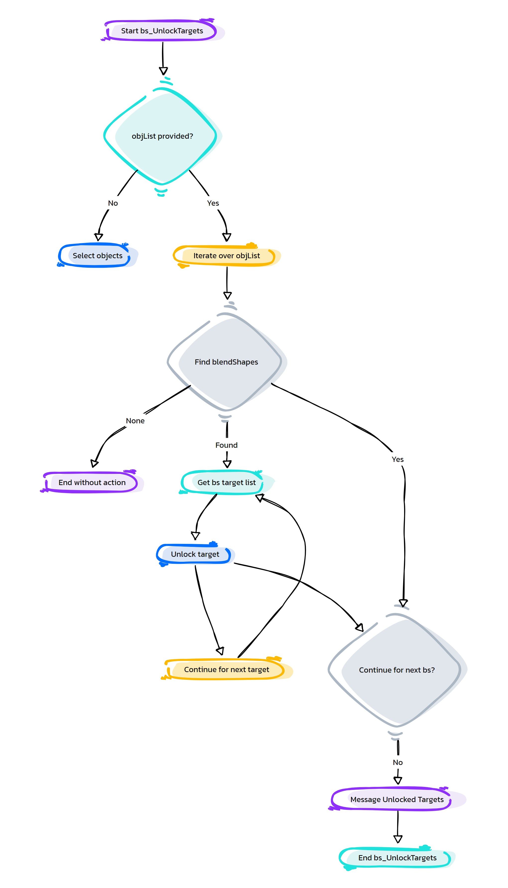
- HyperRig.check4NonUniqueNames(self, selList=None, checkShapes=0, **shArgs)#
[shArgs : sl=selList, cs=checkShapes]
Purpose:
:: Checks the selected list of objects for non-unique names, essential for ensuring the integrity of the scene.
Identifies naming conflicts that can cause issues in scripts and rigging.
Facilitates a cleaner and more organized scene structure.
Prevents potential errors and confusion due to duplicate names.
- Parameters:
selList – <list, optional> # The list of objects to check for non-unique names. If not provided, uses the selected objects.
checkShapes – <bool, optional> # Whether to include shape nodes in the check.
- Returns:
None # This function does not return a value but identifies non-unique names.
Code Examples:
>>> check4NonUniqueNames(selList=['obj1', 'obj2'], checkShapes=False)
# Checks the provided list of objects for non-unique names.
graph TB Start[("fa:fa-play Start")] --> SelectObjects["/fas:fa-mouse-pointer Select Objects"] SelectObjects --> CheckUniqueNames{"/fas:fa-question-circle Check Unique Names"} CheckUniqueNames --"If Non-Unique Names Found"--> MarkNonUnique["/fas:fa-exclamation-triangle Mark Non-Unique"] CheckUniqueNames --"If All Names are Unique"--> DisplayMessage["/fas:fa-check-circle Display Message: No Non-Unique Names"] MarkNonUnique --> CreateSet["/fas:fa-sitemap Create Set for Non-Unique"] CreateSet --> End[("fas:fa-stop End")] DisplayMessage --> End style Start fill:#00cc00,stroke:#000,stroke-width:3px style SelectObjects fill:#ffcc00,stroke:#000,stroke-width:2px style CheckUniqueNames fill:#ff9999,stroke:#000,stroke-width:2px style MarkNonUnique fill:#99ccff,stroke:#000,stroke-width:2px style CreateSet fill:#cc99ff,stroke:#000,stroke-width:2px style DisplayMessage fill:#99ff99,stroke:#000,stroke-width:2px style End fill:#ff6666,stroke:#000,stroke-width:3px- Flow Chart Description:
This flowchart illustrates the check4NonUniqueNames function:
The process begins by selecting objects to check for non-unique names.
- Checks each object in the selection for unique naming.
If non-unique names are found, the objects are marked as non-unique.
If all names are unique, a message is displayed indicating no non-unique names.
Creates a set for objects with non-unique names for easy identification and correction.
Completes the process and ends.
- HyperRig.compareHI(self, srcHI=None, destHI=None, srcPrefix=None, destPrefix=None, **shArgs)#
[shArgs : ]
Purpose:
:: Compares two hierarchies in Maya and identifies non-matching nodes.
This function compares the source and destination hierarchies to find differences.
It is useful for ensuring rigging consistency and identifying discrepancies.
- Parameters:
srcHI – <str> #The source hierarchy for comparison.
destHI – <str> #The destination hierarchy for comparison.
srcPrefix – <str, optional> #Prefix in the source hierarchy for comparison.
destPrefix – <str, optional> #Prefix in the destination hierarchy for comparison.
- Returns:
<set> #A set of nodes that did not match between the two hierarchies.
Code Examples:
>>> srcHI = 'source_hierarchy'
>>> destHI = 'destination_hierarchy'
>>> compareHI(srcHI, destHI)
graph TB Start[("fa:fa-play Start")] --> CheckParameters{{"/fas:fa-question Check Parameters"}} CheckParameters --"If srcHI and destHI are provided" --> ValidateHierarchies[("/fas:fa-check-circle Validate Hierarchies")] CheckParameters --"If srcHI and destHI are not provided" --> GetCurrentSelection[("/fas:fa-mouse-pointer Get Current Selection")] GetCurrentSelection --> ValidateHierarchies ValidateHierarchies --> CheckUniqueNames[("/fas:fa-tags Check Unique Names")] CheckUniqueNames --"If non-unique names exist" --> SelectNonUniqueNodes[("/fas:fa-exclamation-triangle Select Non-Unique Nodes")] CheckUniqueNames --"If all names are unique" --> AdjustPrefixes[("/fas:fa-adjust Adjust Prefixes")] SelectNonUniqueNodes --> End[("fas:fa-stop End")] AdjustPrefixes --> CompareHierarchies[("/fas:fa-balance-scale Compare Hierarchies")] CompareHierarchies --> SelectNonMatchingNodes[("/fas:fa-highlighter Select Non-Matching Nodes")] SelectNonMatchingNodes --> End style Start fill:#00cc00,stroke:#000,stroke-width:3px style CheckParameters fill:#f0ad4e,stroke:#000,stroke-width:2px style GetCurrentSelection fill:#5bc0de,stroke:#000,stroke-width:2px style ValidateHierarchies fill:#5bc0de,stroke:#000,stroke-width:2px style CheckUniqueNames fill:#f0ad4e,stroke:#000,stroke-width:2px style SelectNonUniqueNodes fill:#d9534f,stroke:#000,stroke-width:2px style AdjustPrefixes fill:#5bc0de,stroke:#000,stroke-width:2px style CompareHierarchies fill:#5bc0de,stroke:#000,stroke-width:2px style SelectNonMatchingNodes fill:#5cb85c,stroke:#000,stroke-width:2px style End fill:#ff6666,stroke:#000,stroke-width:3px- Flow Chart Description:
This flowchart outlines the compareHI function:
The process begins by checking if srcHI and destHI are provided.
If not provided, it retrieves the current selection for comparison.
The hierarchies are validated to ensure they exist.
Checks for unique names within the hierarchies. If non-unique names are found, it selects and highlights these nodes.
Adjusts prefixes in the hierarchies if specified.
Compares the hierarchies to identify non-matching nodes.
Selects and highlights the non-matching nodes in the Maya viewport.
- HyperRig.createEyeDeformSetup(self, srcPrfx=None, oppPrfx=None, lidCurv=None, eyesList=None, headMesh=None, upStreamJnt=None, mirrorSetup=True, oppSetup=False, **shArgs)#
[shArgs : sp=srcPrfx, op=oppPrfx, lc=lidCurv, el=eyesList, hm=headMesh, usj=upStreamJnt, ms=mirrorSetup, os=oppSetup]
Purpose:
:: Creates an eye deformation setup with lattice and wire deformers for detailed control over eye and eyelid movements.
Enhances the realism and flexibility of eye animations in character rigs.
Allows for precise control over eyelid deformation and eye mesh adjustments.
Supports both left and right side setups, with mirroring options for symmetrical characters.
- Parameters:
srcPrfx – <str> # Prefix for the source curve and controls.
oppPrfx – <str> # Prefix for the opposite side curve and controls.
lidCurv – <str> # The eyelid curve used for deformation.
eyesList – <list> # List of eye meshes to be deformed.
headMesh – <str> # The head or body mesh affected by the deformation.
upStreamJnt – <str> # The upstream joint to which control groups are constrained.
mirrorSetup – <bool> # Whether to mirror the setup to the opposite side.
oppSetup – <bool> # Whether to create the setup on the opposite side.
- Returns:
None # This function does not return a value but creates an eye deformation setup.
Code Examples:
>>> createEyeDeformSetup(srcPrfx='L', oppPrfx='R', lidCurv='L_EyeLid_Curv', eyesList=['L_Eye_BS', 'L_Eye_Iris_BS'], headMesh='Head_Mesh', upStreamJnt='Head_Jnt', mirrorSetup=True, oppSetup=False)
# Creates an eye deformation setup for the left side with mirroring to the right side.
Args:
srcPrfx = Left Prefix of curves, ..
oppPrfx = Right Prefix of curves, ..
lidCurv = round curve to deform eye lids [Modify -> Convert -> Polygon Edges To Curve (degree-3)]
eyesList = Eyes (blend Shapes) to be deformed by lattice ['L_Eye_BS', 'L_Eye_Iris_BS']
headMesh = bodyMesh / headMesh (blend Shape) to be deformed by lattice
upStreamJnt =head joint [Constraining ('parent', 'scale') control groups to headJnt ]
mirrorSetup =to mirror setup (to be used during first iteration)
oppSetup = to create setup on RH side (Used during second iteration if mirrorSetup is True)
graph TB Start[("fa:fa-play Start")] --> SelectObjects["/fas:fa-mouse-pointer Select Objects"] SelectObjects --> CheckSrcPrfx{"/fas:fa-question-circle Check Source Prefix"} CheckSrcPrfx --"If Source Prefix Given"--> CheckOppPrfx{"/fas:fa-question-circle Check Opposite Prefix"} CheckSrcPrfx --"If Source Prefix Not Given"--> ErrorNoSrcPrfx["/fas:fa-exclamation-triangle Error: No Source Prefix"] CheckOppPrfx --"If Opposite Prefix Given"--> CheckLidCurve{"/fas:fa-question-circle Check Lid Curve"} CheckOppPrfx --"If Opposite Prefix Not Given"--> ErrorNoOppPrfx["/fas:fa-exclamation-triangle Error: No Opposite Prefix"] CheckLidCurve --"If Lid Curve Given"--> CheckEyesList{"/fas:fa-question-circle Check Eyes List"} CheckLidCurve --"If Lid Curve Not Given"--> ErrorNoLidCurve["/fas:fa-exclamation-triangle Error: No Lid Curve"] CheckEyesList --"If Eyes List Given"--> CheckHeadMesh{"/fas:fa-question-circle Check Head Mesh"} CheckEyesList --"If Eyes List Not Given"--> ErrorNoEyesList["/fas:fa-exclamation-triangle Error: No Eyes List"] CheckHeadMesh --"If Head Mesh Given"--> CheckUpStreamJnt{"/fas:fa-question-circle Check Up Stream Joint"} CheckHeadMesh --"If Head Mesh Not Given"--> ErrorNoHeadMesh["/fas:fa-exclamation-triangle Error: No Head Mesh"] CheckUpStreamJnt --"If Up Stream Joint Given"--> CreateEyeDeformSetup["/fas:fa-magic Create Eye Deform Setup"] CheckUpStreamJnt --"If Up Stream Joint Not Given"--> ErrorNoUpStreamJnt["/fas:fa-exclamation-triangle Error: No Up Stream Joint"] CreateEyeDeformSetup --> CheckMirrorSetup{"/fas:fa-question-circle Check Mirror Setup"} CheckMirrorSetup --"If Mirror Setup Enabled"--> MirrorSetup["/fas:fa-exchange-alt Mirror Setup"] CheckMirrorSetup --"If Mirror Setup Not Enabled"--> End[("fas:fa-stop End")] MirrorSetup --> End ErrorNoSrcPrfx --> End ErrorNoOppPrfx --> End ErrorNoLidCurve --> End ErrorNoEyesList --> End ErrorNoHeadMesh --> End ErrorNoUpStreamJnt --> End style Start fill:#00cc00,stroke:#000,stroke-width:3px style SelectObjects fill:#ffcc00,stroke:#000,stroke-width:2px style CheckSrcPrfx fill:#ff9999,stroke:#000,stroke-width:2px style CheckOppPrfx fill:#99ccff,stroke:#000,stroke-width:2px style CheckLidCurve fill:#cc99ff,stroke:#000,stroke-width:2px style CheckEyesList fill:#99ff99,stroke:#000,stroke-width:2px style CheckHeadMesh fill:#ffcc99,stroke:#000,stroke-width:2px style CheckUpStreamJnt fill:#ccffcc,stroke:#000,stroke-width:2px style CreateEyeDeformSetup fill:#99ccff,stroke:#000,stroke-width:2px style CheckMirrorSetup fill:#cc99ff,stroke:#000,stroke-width:2px style MirrorSetup fill:#99ff99,stroke:#000,stroke-width:2px style ErrorNoSrcPrfx fill:#ff9999,stroke:#000,stroke-width:2px style ErrorNoOppPrfx fill:#ccffcc,stroke:#000,stroke-width:2px style ErrorNoLidCurve fill:#ffcc99,stroke:#000,stroke-width:2px style ErrorNoEyesList fill:#99ccff,stroke:#000,stroke-width:2px style ErrorNoHeadMesh fill:#cc99ff,stroke:#000,stroke-width:2px style ErrorNoUpStreamJnt fill:#99ff99,stroke:#000,stroke-width:2px style End fill:#ff6666,stroke:#000,stroke-width:3px- Flow Chart Description:
This flowchart illustrates the createEyeDeformSetup function:
Begins by selecting objects for the setup.
Checks if the source prefix is provided. If not, displays an error message.
Checks for the opposite prefix. If not provided, displays an error message.
Verifies the existence of a lid curve. If absent, displays an error message.
Confirms the list of eye meshes. If not given, displays an error message.
Ensures the head mesh is specified. If not, displays an error message.
Checks if an upstream joint is provided. If absent, displays an error message.
Creates the eye deformation setup.
Checks if the mirror setup option is enabled. If so, mirrors the setup to the opposite side.
Completes the process and ends.
- HyperRig.createVisSwitch(self, otherAttrs=False, **shArgs)#
[shArgs : oa=otherAttrs]
Purpose:
:: Creates a visibility switch control for various components such as meshes and controllers.
Essential for managing scene complexity by toggling the visibility of different elements.
Enhances the animator’s workflow by providing quick access to hide or show components.
Customizable to include additional attributes like global scale or mesh smoothness.
- Parameters:
otherAttrs – <bool> # Whether to include additional attributes like global scale or mesh detail.
- Returns:
None # This function does not return a value but creates a visibility switch on the specified control.
Code Examples:
>>> createVisSwitch(otherAttrs=True)
# Creates a visibility switch with additional attributes on the selected control.
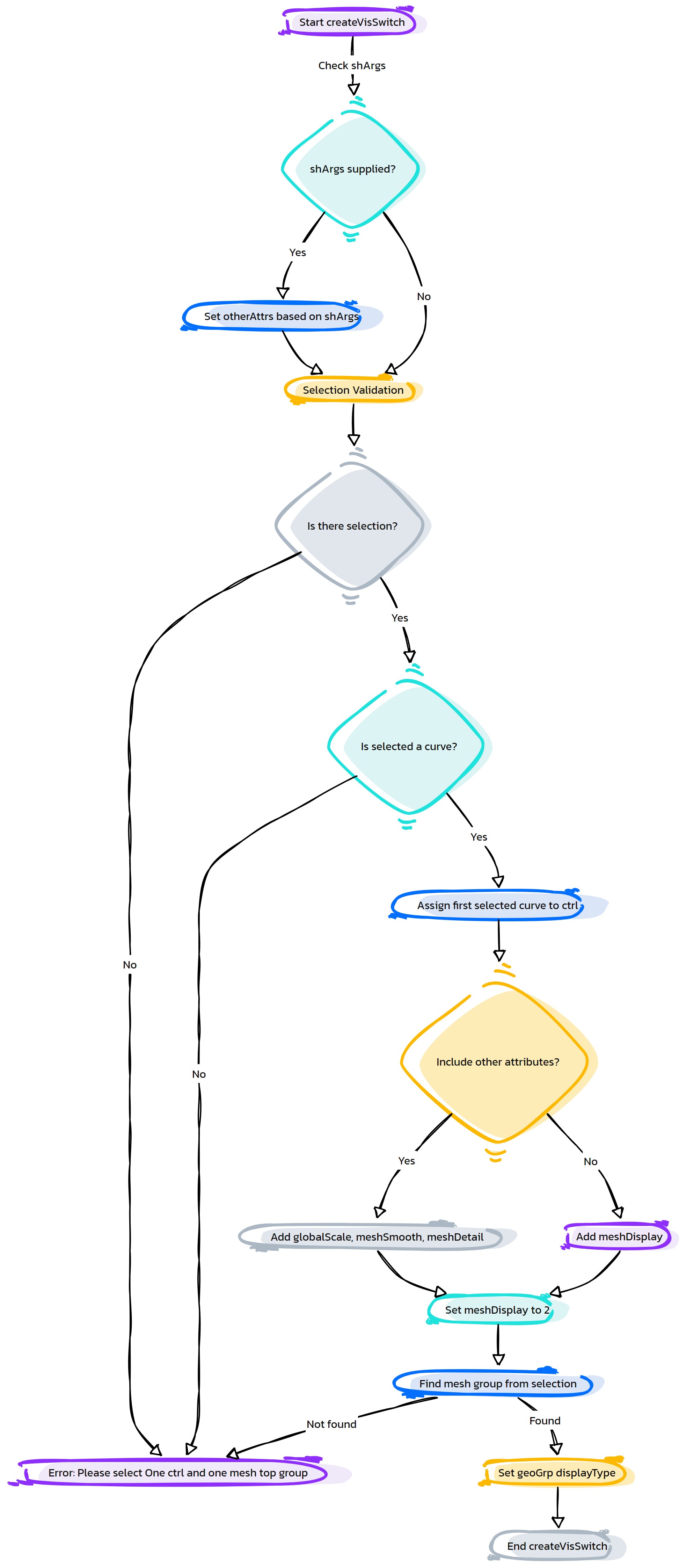
- HyperRig.dynamicOptionsMenu(self, **shArgs)#
[shArgs: ]
Purpose:
:: Creates or updates the dynamic options menu for hair systems in the as_HyperRig UI.
This function manages the dynamic listing of available hair systems for user selection within as_HyperRig.
- Returns:
None # This function does not return any value but updates the hair systems options menu in the as_HyperRig UI.
Code Examples:
>>> dynamicOptionsMenu()
# Updates the hair systems options menu in as_HyperRig.
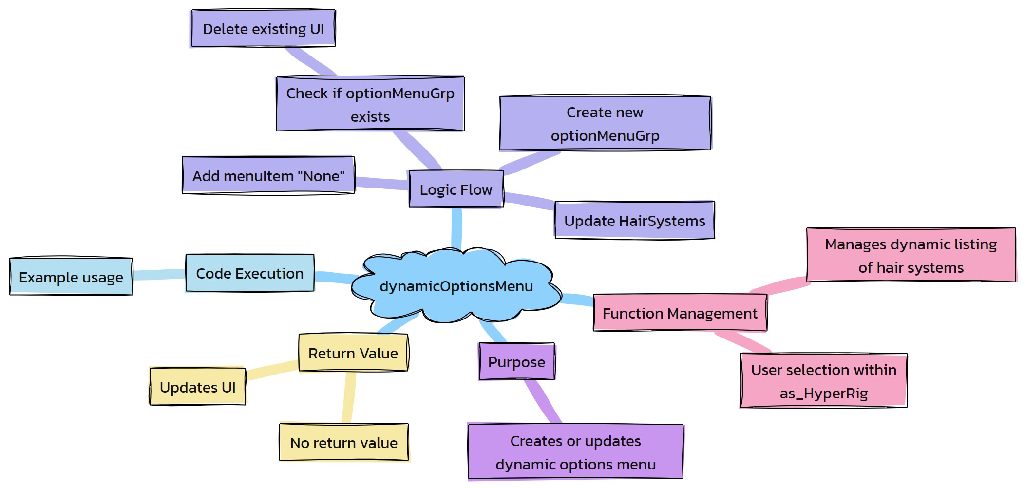
- HyperRig.fixVtxList_MoreThan5Infs(self, vtxList=None, limitInfs=5, **shArgs)#
[shArgs : vl=vtxList, li=limitInfs]
Purpose:
:: Reduces the number of joint influences on vertices to a specified limit for better skinning quality.
Essential for optimizing skinning and improving deformation quality.
Reduces the complexity of skin weight painting by limiting the number of influences.
Helps in maintaining a cleaner and more manageable rigging setup.
- Parameters:
vtxList – <list> # The list of vertices to be fixed. If not provided, uses the selected vertices or mesh.
limitInfs – <int> # The maximum number of influences allowed on each vertex.
- Returns:
None # This function does not return a value but modifies the influences on the specified vertices.
Code Examples:
>>> fixVtxList_MoreThan5Infs(vtxList=['mesh.vtx[0]', 'mesh.vtx[1]'], limitInfs=5)
# Limits the influences on the specified vertices to a maximum of 5.
graph TB Start[("fa:fa-play Start")] --> SelectVertices["/fas:fa-th Select Vertices"] SelectVertices --> CheckVtxList{"/fas:fa-question-circle Check Vtx List"} CheckVtxList --"If Vtx List Provided"--> ProcessVtxList["/fas:fa-cogs Process Vtx List"] CheckVtxList --"If No Vtx List Provided"--> SelectMesh["/fas:fa-mouse-pointer Select Mesh"] SelectMesh --> GetMeshVertices["/fas:fa-object-group Get Mesh Vertices"] GetMeshVertices --> ProcessVtxList ProcessVtxList --> RetrieveSkinCluster["/fas:fa-link Retrieve Skin Cluster"] RetrieveSkinCluster --> GetInfluences["/fas:fa-user-friends Get Influences"] GetInfluences --> SetMaxInfluences["/fas:fa-sliders-h Set Max Influences"] SetMaxInfluences --> UpdateSkinWeights["/fas:fa-weight Update Skin Weights"] UpdateSkinWeights --> End[("fas:fa-stop End")] style Start fill:#00cc00,stroke:#000,stroke-width:3px style SelectVertices fill:#ffcc00,stroke:#000,stroke-width:2px style CheckVtxList fill:#ff9999,stroke:#000,stroke-width:2px style ProcessVtxList fill:#99ccff,stroke:#000,stroke-width:2px style SelectMesh fill:#cc99ff,stroke:#000,stroke-width:2px style GetMeshVertices fill:#99ff99,stroke:#000,stroke-width:2px style RetrieveSkinCluster fill:#ffcc99,stroke:#000,stroke-width:2px style GetInfluences fill:#ccffcc,stroke:#000,stroke-width:2px style SetMaxInfluences fill:#99ccff,stroke:#000,stroke-width:2px style UpdateSkinWeights fill:#cc99ff,stroke:#000,stroke-width:2px style End fill:#ff6666,stroke:#000,stroke-width:3px- Flow Chart Description:
This flowchart illustrates the fixVtxList_MoreThan5Infs function:
Begins by selecting the vertices to be processed.
- Checks if a list of vertices is provided.
If a vertex list is provided, it processes the given list.
If no list is provided, it selects a mesh and retrieves all vertices.
Retrieves the skin cluster associated with the vertices.
Gathers all influencing joints for the vertices.
Limits the maximum number of influences per vertex to the specified limit.
Updates the skin weights according to the new influence limit.
Completes the process and ends.
- HyperRig.flipMesh_ForCorrectiveShape(self, **shArgs)#
[shArgs : sms=LMesh_Src, t=asVtx, rt=RMesh_Trgt]
Purpose:
:: Flips a mesh for creating symmetrical corrective shapes, often used in character rigging.
Facilitates the creation of symmetrical corrective shapes by mirroring one side of the mesh to the other.
Enhances the efficiency of the rigging process for symmetrical characters.
Reduces the time spent manually creating corrective shapes for both sides of a character.
- Parameters:
LMesh_Src – <str> # The source mesh to be flipped (typically the left side).
asVtx – <str> # A vertex or object on the target mesh where the flipped mesh will be aligned.
RMesh_Trgt – <str> # The target mesh to receive the flipped shape (typically the right side).
- Returns:
None # This function does not return a value but creates a flipped version of the source mesh on the target mesh.
Code Examples:
>>> flipMesh_ForCorrectiveShape(LMesh_Src='L_WingClose', asVtx='vertexOnR_WingClose', RMesh_Trgt='R_WingClose')
# Flips the left wing mesh to the right wing mesh for corrective shape creation.
graph TB Start[("fa:fa-play Start")] --> SelectMeshes["/fas:fa-mouse-pointer Select Meshes"] SelectMeshes --> ValidateSelection{"/fas:fa-question-circle Validate Selection"} ValidateSelection --"If Source and Target Meshes Valid"--> FlipMeshProcess["/fas:fa-random Flip Mesh Process"] ValidateSelection --"If Invalid Selection"--> ErrorInvalidSelection["/fas:fa-exclamation-triangle Error: Invalid Selection"] FlipMeshProcess --> AlignToVertex{"/fas:fa-arrows-alt Align To Vertex"} AlignToVertex --> CreateFlippedShape["/fas:fa-object-group Create Flipped Shape"] CreateFlippedShape --> End[("fas:fa-stop End")] ErrorInvalidSelection --> End style Start fill:#00cc00,stroke:#000,stroke-width:3px style SelectMeshes fill:#ffcc00,stroke:#000,stroke-width:2px style ValidateSelection fill:#ff9999,stroke:#000,stroke-width:2px style FlipMeshProcess fill:#99ccff,stroke:#000,stroke-width:2px style AlignToVertex fill:#cc99ff,stroke:#000,stroke-width:2px style CreateFlippedShape fill:#99ff99,stroke:#000,stroke-width:2px style ErrorInvalidSelection fill:#ff6666,stroke:#000,stroke-width:2px style End fill:#ff6666,stroke:#000,stroke-width:3px- Flow Chart Description:
This flowchart illustrates the flipMesh_ForCorrectiveShape function:
Starts with the selection of meshes involved in the flipping process.
- Validates the selection to ensure the source and target meshes are appropriate.
If the selection is valid, proceeds to flip the mesh.
If the selection is invalid, raises an error and ends the process.
Executes the mesh flipping process, aligning the flipped mesh to a specific vertex on the target mesh.
Creates the flipped shape on the target mesh.
Completes the process and ends.
- HyperRig.getConstraints(self, transform_node, constraint_type=None, **shArgs)#
[shArgs : tn=transform_node, ct=constraint_type]
Purpose:
:: Retrieves all constraint nodes associated with a specified transform node in Maya.
Useful for rigging and animation, allowing for efficient constraint management.
Supports filtering by specific constraint types, such as point, orient, or parent.
Facilitates the identification and manipulation of constraints in complex setups.
- Parameters:
transform_node – <str> # The transform node to search for constraints.
constraint_type – <str, optional> # Specific type of constraint to filter the search.
- Returns:
<list> # A list of constraint nodes associated with the transform node.
Code Examples:
>>> constraints = getConstraints(transform_node='characterCtrl', constraint_type='orient')
# Retrieves all orient constraints associated with 'characterCtrl'.
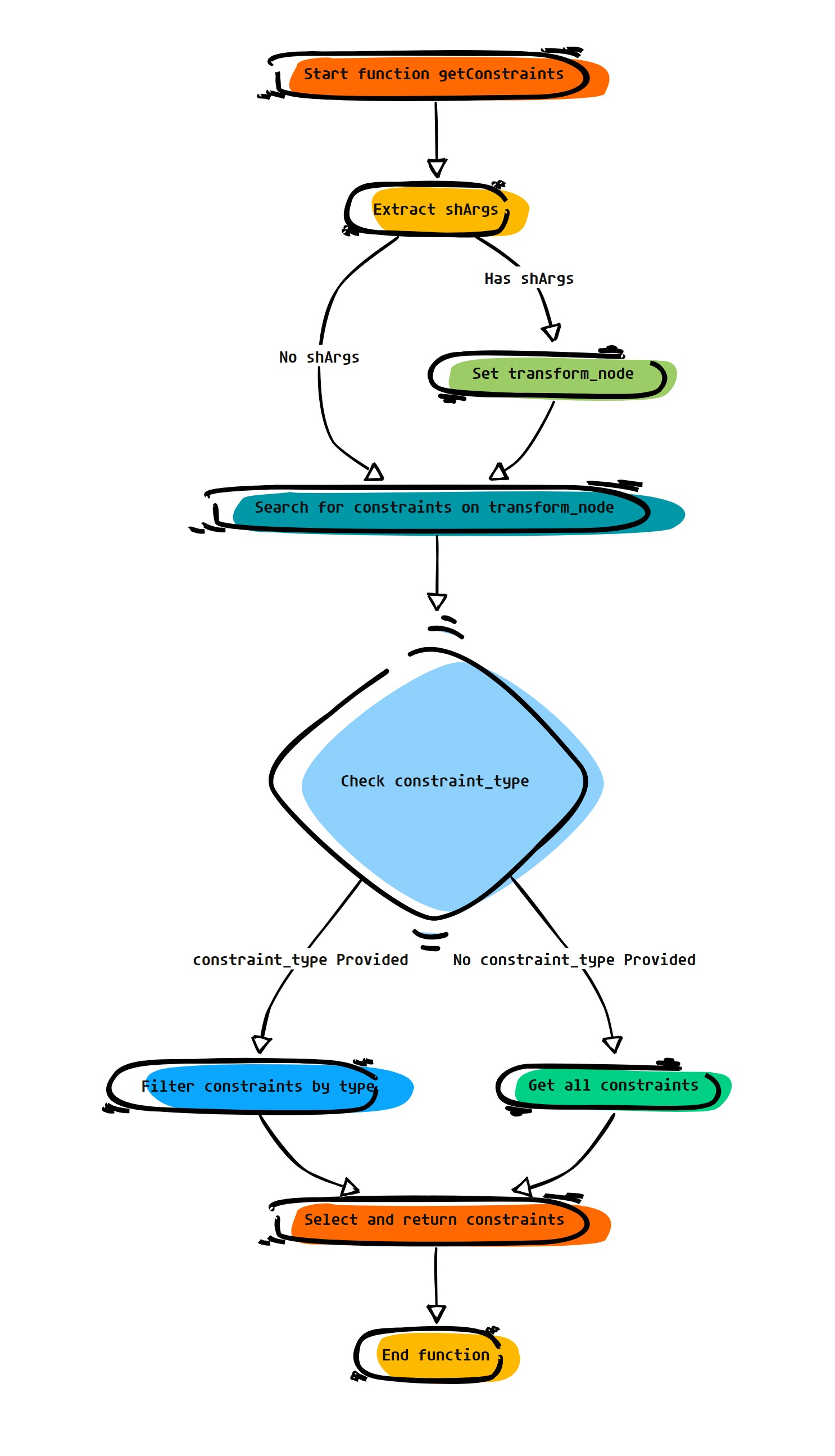 graph TB Start[("fa:fa-play Start")] --> SelectHierarchy["/fas:fa-sitemap Select Hierarchy"] SelectHierarchy --> CheckConstraintType{"/fas:fa-question-circle Check Constraint Type"} CheckConstraintType --"If Specific Constraint Type Given"--> FilterConstraints["/fas:fa-filter Filter Constraints"] CheckConstraintType --"If No Specific Type Given"--> GetAllConstraints["/fas:fa-list GetAll Constraints"] FilterConstraints --> ReturnConstraints["/fas:fa-check Return Constraints"] GetAllConstraints --> ReturnConstraints ReturnConstraints --> End[("fas:fa-stop End")] style Start fill:#00cc00,stroke:#000,stroke-width:3px style SelectHierarchy fill:#ffcc00,stroke:#000,stroke-width:2px style CheckConstraintType fill:#ff9999,stroke:#000,stroke-width:2px style FilterConstraints fill:#99ccff,stroke:#000,stroke-width:2px style GetAllConstraints fill:#cc99ff,stroke:#000,stroke-width:2px style ReturnConstraints fill:#99ff99,stroke:#000,stroke-width:2px style End fill:#ff6666,stroke:#000,stroke-width:3px
- Flow Chart Description:
This flowchart illustrates the getConstraints function:
The function starts by selecting the entire hierarchy of the specified transform node.
- It checks if a specific constraint type is given.
If a specific constraint type is given, it filters the constraints to match the specified type.
If no specific constraint type is provided, it retrieves all constraint nodes.
Returns the list of retrieved constraint nodes.
Completes the process and ends.
- HyperRig.getCorrective_CVSI(self, keepHistory=0, useMayaCmd=1, **shArgs)#
[shArgs : sm=skinMesh, tm=trgtMesh, kh=keepHistory, umc=useMayaCmd]
Purpose:
:: Generates a corrective blend shape (CBS) by inverting the shape difference between the original and the corrected mesh.
Essential for creating corrective shapes in character rigs, especially for high-quality skin deformations.
Facilitates the process of generating inverse shapes for blend shape corrections.
Supports both native Maya commands and the CV Shape Inverter tool.
- Parameters:
skinMesh – <str> # The original skinned mesh to compare.
trgtMesh – <str> # The target mesh with the corrective shape.
keepHistory – <bool> # Determines whether to keep the history on the inverted shape (True) or delete it (False).
useMayaCmd – <bool> # Specifies whether to use Maya’s native commands (True) or the CV Shape Inverter tool (False).
- Returns:
<str> # The name of the newly created corrective blend shape.
Code Examples:
>>> getCorrective_CVSI(skinMesh='baseMesh', trgtMesh='correctedMesh', keepHistory=False, useMayaCmd=True)
# Generates a corrective blend shape from the difference between 'baseMesh' and 'correctedMesh'.
graph TB Start[("fa:fa-play Start")] --> SelectMeshes["/fas:fa-sitemap Select Meshes"] SelectMeshes --> CheckSelectedMeshes{"/fas:fa-question-circle Check Selected Meshes"} CheckSelectedMeshes --"If Two Meshes Selected"--> InvertShape["/fas:fa-exchange-alt Invert Shape"] CheckSelectedMeshes --"If Not Two Meshes Selected"--> ErrorMeshSelection["/fas:fa-exclamation-triangle Error: Incorrect Mesh Selection"] InvertShape --"Using Maya Cmd"--> MayaInvertShape["/fas:fa-cogs Maya Invert Shape"] InvertShape --"Using CV Shape Inverter"--> CVShapeInverter["/fas:fa-cogs CV Shape Inverter"] MayaInvertShape --> RenameInvertedShape["/fas:fa-pencil-alt Rename Inverted Shape"] CVShapeInverter --> RenameInvertedShape RenameInvertedShape --> FinalizeCBS["/fas:fa-check-circle Finalize Corrective Blend Shape"] FinalizeCBS --> End[("fas:fa-stop End")] ErrorMeshSelection --> End style Start fill:#00cc00,stroke:#000,stroke-width:3px style SelectMeshes fill:#ffcc00,stroke:#000,stroke-width:2px style CheckSelectedMeshes fill:#ff9999,stroke:#000,stroke-width:2px style InvertShape fill:#99ccff,stroke:#000,stroke-width:2px style MayaInvertShape fill:#cc99ff,stroke:#000,stroke-width:2px style CVShapeInverter fill:#99ff99,stroke:#000,stroke-width:2px style RenameInvertedShape fill:#ffcc99,stroke:#000,stroke-width:2px style FinalizeCBS fill:#ccffcc,stroke:#000,stroke-width:2px style ErrorMeshSelection fill:#ff9999,stroke:#000,stroke-width:2px style End fill:#ff6666,stroke:#000,stroke-width:3px- Flow Chart Description:
This flowchart illustrates the getCorrective_CVSI function:
The process starts with selecting the original skinned mesh and the corrected target mesh.
- The function checks if two meshes are selected correctly.
If two meshes are selected, it proceeds to invert the shape.
If not, an error is raised for incorrect mesh selection.
Inverts the shape of the corrected mesh using either Maya commands or the CV Shape Inverter tool.
Renames the inverted shape to indicate it’s a corrective blend shape (CBS).
Finalizes the creation of the corrective blend shape and ends the process.
- HyperRig.getInfluencesFromVtx(self, **shArgs)#
[shArgs : ]
Purpose:
:: Retrieves the influencing joints of a selected vertex, typically for skinning purposes.
Useful in character rigging and skinning to analyze and adjust vertex influences.
Provides a quick method to select and view the joints influencing a particular vertex.
Enhances the process of skin weight painting by allowing easy access to influence data.
:param : # No arguments required.
- Returns:
None # This function does not return a value but selects the influencing joints of the chosen vertex.
Code Examples:
>>> getInfluencesFromVtx()
# Selects joints influencing the currently selected vertex.
graph TB Start[("fa:fa-play Start")] --> SelectVertex["/fas:fa-dot-circle Select Vertex"] SelectVertex --> GetSkinWeights{"/fas:fa-balance-scale Get Skin Weights"} GetSkinWeights --> RetrieveJoints["/fas:fa-sitemap Retrieve Influencing Joints"] RetrieveJoints --> SelectJoints["/fas:fa-mouse-pointer Select Influencing Joints"] SelectJoints --> End[("fas:fa-stop End")] style Start fill:#00cc00,stroke:#000,stroke-width:3px style SelectVertex fill:#ffcc00,stroke:#000,stroke-width:2px style GetSkinWeights fill:#ff9999,stroke:#000,stroke-width:2px style RetrieveJoints fill:#99ccff,stroke:#000,stroke-width:2px style SelectJoints fill:#cc99ff,stroke:#000,stroke-width:2px style End fill:#ff6666,stroke:#000,stroke-width:3px- Flow Chart Description:
This flowchart illustrates the getInfluencesFromVtx function:
The process begins by selecting a vertex on the mesh.
Retrieves the skin weights associated with the selected vertex.
Identifies the influencing joints based on the skin weight data.
Selects the influencing joints in the Maya scene.
Completes the process and ends.
- HyperRig.getModelFile_HR(self, **shArgs)#
[shArgs : sp=srcPath, df=destFile]
Purpose:
:: Opens a file dialog for selecting a high-resolution Maya model file.
Facilitates the selection of Maya files (.ma, .mb) directly from a user interface.
Streamlines the process of sourcing high-resolution model files for import or reference in Maya.
Automatically updates the specified text field with the selected file path.
- Parameters:
srcPath – <str> # The initial directory path to open the file dialog in.
destFile – <str> # The destination file path chosen by the user.
- Returns:
None # This function does not return a value but updates the UI text field with the selected file path.
Code Examples:
>>> getModelFile_HR()
# Opens a file dialog for selecting a Maya model file and updates the UI text field.
graph TB Start[("fa:fa-play Start")] --> OpenDialog["/fas:fa-folder-open Open File Dialog"] OpenDialog --> UpdateTextField["/fas:fa-edit Update Text Field"] UpdateTextField --> End[("fas:fa-stop End")] style Start fill:#00cc00,stroke:#000,stroke-width:3px style OpenDialog fill:#ffcc00,stroke:#000,stroke-width:2px style UpdateTextField fill:#99ccff,stroke:#000,stroke-width:2px style End fill:#ff6666,stroke:#000,stroke-width:3px- Flow Chart Description:
This flowchart illustrates the getModelFile_HR function:
The process starts by opening a file dialog, allowing the user to select a Maya model file (.ma or .mb).
Once a file is selected, the function updates a UI text field with the chosen file path.
The process ends after updating the text field.
- HyperRig.getPosJoints(self, **shArgs)#
[shArgs : ]
Purpose:
:: Generates position joints for selected objects in Maya.
Useful in rigging for creating joints that match the position of selected objects.
Streamlines the process of joint creation in alignment with existing scene elements.
Can be used for various purposes like rigging, dynamics, or proxy setups.
:param : # No arguments required.
- Returns:
None # This function does not return a value but creates joints at the positions of selected objects.
Code Examples:
>>> getPosJoints()
# Creates position joints for each selected object in Maya.
graph TB Start[("fa:fa-play Start")] --> SelectObjects["/fas:fa-mouse-pointer Select Objects"] SelectObjects --> GeneratePosJoints["/fas:fa-plus-square Generate Position Joints"] GeneratePosJoints --> End[("fas:fa-stop End")] style Start fill:#00cc00,stroke:#000,stroke-width:3px style SelectObjects fill:#ffcc00,stroke:#000,stroke-width:2px style GeneratePosJoints fill:#99ccff,stroke:#000,stroke-width:2px style End fill:#ff6666,stroke:#000,stroke-width:3px- Flow Chart Description:
This flowchart illustrates the getPosJoints function:
The process begins with the selection of objects in the Maya scene.
For each selected object, the function creates a joint positioned at the object’s location.
The process concludes after creating position joints for all selected objects.
- HyperRig.getPosLocators(self, makeChild=1, snapRot=0, hideLoc=1, oppAxis=None, **shArgs)#
[shArgs : ol=objList, mc=makeChild, sr=snapRot, hl=hideLoc, oa=oppAxis]
Purpose:
:: Generates position locators for selected objects in Maya.
Useful for tracking and saving the positions of objects in the scene.
Allows for creation of locators as children of the objects or as separate entities.
Can mirror locators across an axis for symmetrical setups.
- Parameters:
objList – <list> # List of objects to create position locators for.
makeChild – <int> # Whether to make the locator a child of the object (1) or not (0).
snapRot – <int> # Whether to snap the locator’s rotation to the object’s rotation (1) or not (0).
hideLoc – <int> # Whether to hide the locator (1) or keep it visible (0).
oppAxis – <str, optional> # Axis to mirror the locators, if required.
- Returns:
<list> # List of created position locators.
Code Examples:
>>> getPosLocators(makeChild=1, snapRot=1, hideLoc=0, oppAxis='x')
# Creates position locators for selected objects, snapping rotation, and mirroring across the x-axis.
graph TB Start[("fa:fa-play Start")] --> GetSelectedObjects["/fas:fa-mouse-pointer Get Selected Objects"] GetSelectedObjects --> GenerateLocators{"/fas:fa-map-pin Generate Locators"} GenerateLocators --"For Each Selected Object"--> CreatePositionLocator["/fas:fa-thumbtack Create Position Locator"] CreatePositionLocator --> CheckMakeChild{{"/fas:fa-question-circle Check Make Child"}} CheckMakeChild --"If MakeChild is 1"--> MakeChildOfObject["/fas:fa-link Make Child of Object"] CheckMakeChild --"If MakeChild is 0"--> AddToGroup["/fas:fa-object-group Add to Group"] MakeChildOfObject --> HideLocator[("/fas:fa-eye-slash Hide Locator")] AddToGroup --> HideLocator HideLocator --> CheckMirrorAxis{{"/fas:fa-question-circle Check Mirror Axis"}} CheckMirrorAxis --"If Mirror Axis is Specified"--> MirrorLocators["/fas:fa-arrows-alt-h Mirror Locators"] CheckMirrorAxis --"If No Mirror Axis"--> End[("fas:fa-stop End")] MirrorLocators --> End style Start fill:#00cc00,stroke:#000,stroke-width:3px style GetSelectedObjects fill:#ffcc00,stroke:#000,stroke-width:2px style GenerateLocators fill:#ff9999,stroke:#000,stroke-width:2px style CreatePositionLocator fill:#99ccff,stroke:#000,stroke-width:2px style CheckMakeChild fill:#cc99ff,stroke:#000,stroke-width:2px style MakeChildOfObject fill:#99ff99,stroke:#000,stroke-width:2px style AddToGroup fill:#ffcc99,stroke:#000,stroke-width:2px style HideLocator fill:#ccffcc,stroke:#000,stroke-width:2px style CheckMirrorAxis fill:#ff9999,stroke:#000,stroke-width:2px style MirrorLocators fill:#99ccff,stroke:#000,stroke-width:2px style End fill:#ff6666,stroke:#000,stroke-width:3px- Flow Chart Description:
This flowchart illustrates the getPosLocators function:
Begins by obtaining a list of selected objects in the scene.
For each selected object, a position locator is created and configured.
Checks if the locator should be made a child of the object.
If makeChild is set to 1, the locator is parented to the object.
If makeChild is 0, the locator is added to a group.
Determines if the locator should be hidden based on the hideLoc parameter.
Checks if there is a specified axis for mirroring the locators.
If an axis is provided, mirrors the locators across the specified axis.
Completes the process by selecting the created locators.
- HyperRig.getPoseReaderLoc(self, trgtDir='x', selectLoc=False, connect=False, getAngle=0, **shArgs)#
[shArgs : td=trgtDir, sl=selectLoc, cn=connect, ga=getAngle]
Purpose:
:: Creates and manages pose reader locators in Maya for rigging.
Essential for creating pose-based deformations or corrective shapes in character rigs.
Allows selection of existing pose locators or creation of new ones based on joint orientation.
Offers options to automatically connect pose readers and retrieve angle information.
- Parameters:
trgtDir – <str> # The target direction for the pose reader, e.g., ‘x’, ‘-x’.
selectLoc – <bool> # Determines whether to select an existing locator (True) or create a new one (False).
connect – <bool> # Whether to connect the pose reader locators automatically.
getAngle – <int> # Whether to retrieve the angle information from the pose reader.
- Returns:
None # This function does not return a value but creates or manipulates pose reader locators.
Code Examples:
>>> getPoseReaderLoc(trgtDir='x', selectLoc=False, connect=True, getAngle=1)
# Creates and connects pose reader locators in the 'x' direction and retrieves angle information.
graph TB Start[("fa:fa-play Start")] --> SelectJoints["/fas:fa-sitemap Select Joints"] SelectJoints --> CheckSelection{"/fas:fa-question-circle Check Selection"} CheckSelection --"If Joints Selected"--> CreateBaseLocators["/fas:fa-plus-square Create Base Locators"] CheckSelection --"If No Joints Selected"--> ErrorNoJoints["/fas:fa-exclamation-triangle Error: No Joints Selected"] CreateBaseLocators --> CreatePoseLocators["/fas:fa-plus-square Create Pose Locators"] CreatePoseLocators --> CreateTargetLocators["/fas:fa-plus-square Create Target Locators"] CreateTargetLocators --> ConnectPoseReader{"/fas:fa-link Connect Pose Reader"} ConnectPoseReader --"If Connect Option Selected"--> ApplyPoseReader["/fas:fa-cogs Apply Pose Reader"] ApplyPoseReader --> End[("fas:fa-stop End")] ConnectPoseReader --"If Connect Option Not Selected"--> End ErrorNoJoints --> End style Start fill:#00cc00,stroke:#000,stroke-width:3px style SelectJoints fill:#ffcc00,stroke:#000,stroke-width:2px style CheckSelection fill:#ff9999,stroke:#000,stroke-width:2px style CreateBaseLocators fill:#99ccff,stroke:#000,stroke-width:2px style CreatePoseLocators fill:#cc99ff,stroke:#000,stroke-width:2px style CreateTargetLocators fill:#99ff99,stroke:#000,stroke-width:2px style ConnectPoseReader fill:#ffcc99,stroke:#000,stroke-width:2px style ApplyPoseReader fill:#ccffcc,stroke:#000,stroke-width:2px style ErrorNoJoints fill:#ff9999,stroke:#000,stroke-width:2px style End fill:#ff6666,stroke:#000,stroke-width:3px- Flow Chart Description:
This flowchart illustrates the getPoseReaderLoc function:
The function begins with selecting joints in the Maya scene.
- It checks if joints are selected:
If joints are selected, it proceeds to create base locators.
If no joints are selected, an error is raised.
Creates pose locators at the joint positions.
Generates target locators based on the joint hierarchy.
If the connect option is selected, it connects pose reader locators.
Applies the pose reader setup and completes the process.
- HyperRig.getSkinCluster02(self, meshTransform, **shArgs)#
[shArgs: ]
Purpose:
:: Retrieves the skin cluster associated with a given mesh transform node in Autodesk Maya.
This function is used in rigging and skinning workflows to access and manipulate skin cluster nodes attached to a mesh.
- Parameters:
meshTransform – <str> # The name of the mesh transform node.
- Returns:
<list> # Returns a list containing the name of the skin cluster and the MFnSkinCluster object.
Code Examples:
>>> mesh_transform = "character_mesh"
>>> skin_cluster = getSkinCluster02(mesh_transform)
# Retrieves the skin cluster associated with the specified mesh transform node.
graph TB Start[("fa:fa-play Start")] --> GetShapeNode[("/fas:fa-cogs Get Shape Node")] GetShapeNode --"Retrieve shape node from mesh transform" --> FindSkinCluster[("/fas:fa-search Find SkinCluster")] FindSkinCluster --"Identify connected SkinCluster node" --> GetNumVertices[("/fas:fa-sort-numeric-up Get Number of Vertices")] GetNumVertices --"Calculate vertices count in shape" --> CreateSelList[("/fas:fa-list Create Selection List")] CreateSelList --"Generate selection list for shape and SkinCluster" --> GetDagPathSkinDep[("/fas:fa-sitemap Get DAG Path and Skin Dependence")] GetDagPathSkinDep --"Retrieve DAG path for shape and MObject for SkinCluster" --> CreateMFnSkinCluster[("/fas:fa-puzzle-piece Create MFnSkinCluster")] CreateMFnSkinCluster --"Instantiate MFnSkinCluster for SkinCluster node" --> End[("fas:fa-stop-circle End")] style Start fill:#00cc00,stroke:#000,stroke-width:3px style GetShapeNode fill:#ffcc00,stroke:#000,stroke-width:2px style FindSkinCluster fill:#5bc0de,stroke:#000,stroke-width:2px style GetNumVertices fill:#f0ad4e,stroke:#000,stroke-width:2px style CreateSelList fill:#5cb85c,stroke:#000,stroke-width:2px style GetDagPathSkinDep fill:#d9534f,stroke:#000,stroke-width:2px style CreateMFnSkinCluster fill:#337ab7,stroke:#000,stroke-width:2px style End fill:#ff6666,stroke:#000,stroke-width:3px- Flow Chart Description:
This flowchart illustrates the getSkinCluster02 function:
The process starts by retrieving the shape node from the given mesh transform.
It then identifies the connected SkinCluster node.
The number of vertices in the shape is calculated.
A selection list is created for both the shape and SkinCluster nodes.
The function retrieves the DAG path for the shape and the MObject for the SkinCluster.
An MFnSkinCluster object is instantiated for the SkinCluster node.
The function concludes by returning the name of the SkinCluster node and the MFnSkinCluster object.
- HyperRig.getSkinJnts(self, skinMesh, allInfs=False, **shArgs)#
[shArgs: ]
Purpose:
:: Retrieves the list of joints influencing a skinned mesh in Autodesk Maya.
This function is used in skinning workflows to obtain a list of joints that are influencing a specified skinned mesh.
- Parameters:
skinMesh – <str> # The name of the skinned mesh.
allInfs – <bool> # Determines whether to retrieve all influencing joints or only those with weights.
- Returns:
<list> # Returns a list of joints influencing the specified skinned mesh.
Code Examples:
>>> mesh_name = "character_mesh"
>>> all_influences = True
>>> skin_joints = getSkinJnts(mesh_name, all_influences)
# Retrieves the list of joints influencing the specified skinned mesh.
graph TB Start[("fa:fa-play Start")] --> CheckSkinMesh[("/fas:fa-question-circle Check Skin Mesh")] CheckSkinMesh --"If Skin Mesh Exists" --> RetrieveSkinCluster[("/fas:fa-search Retrieve Skin Cluster")] CheckSkinMesh --"If No Skin Mesh" --> End[("fas:fa-stop-circle End")] RetrieveSkinCluster --"If Skin Cluster Exists" --> CheckAllInfs[("/fas:fa-check-square Check All Influences")] RetrieveSkinCluster --"If No Skin Cluster" --> DisplayError[("/fas:fa-exclamation-triangle Display Error")] CheckAllInfs --"If All Influences" --> GetInfluencingJoints[("/fas:fa-bone Get All Influencing Joints")] CheckAllInfs --"If Not All Influences" --> GetWeightedJoints[("/fas:fa-balance-scale Get Weighted Influencing Joints")] GetInfluencingJoints --> ReturnJointList[("/fas:fa-list Return List of Joints")] GetWeightedJoints --> ReturnJointList DisplayError --> End style Start fill:#00cc00,stroke:#000,stroke-width:3px style CheckSkinMesh fill:#ffcc00,stroke:#000,stroke-width:2px style RetrieveSkinCluster fill:#5bc0de,stroke:#000,stroke-width:2px style CheckAllInfs fill:#ffcc00,stroke:#000,stroke-width:2px style GetInfluencingJoints fill:#5bc0de,stroke:#000,stroke-width:2px style GetWeightedJoints fill:#5bc0de,stroke:#000,stroke-width:2px style ReturnJointList fill:#5bc0de,stroke:#000,stroke-width:2px style DisplayError fill:#d9534f,stroke:#000,stroke-width:2px style End fill:#ff6666,stroke:#000,stroke-width:3px- Flow Chart Description:
This flowchart illustrates the getSkinJnts function:
The process starts by checking if the specified skin mesh exists.
If the skin mesh exists, it retrieves the associated skin cluster.
If the skin cluster exists, it checks whether to retrieve all influencing joints or only those with weights.
Retrieves either all influencing joints or only the weighted influencing joints based on the allInfs parameter.
Returns the list of influencing joints.
If the skin cluster is not found, an error is displayed and the process ends.
- HyperRig.getVtxList_MoreThan5Infs(self, vtxList=None, numInfs=5, **shArgs)#
[shArgs : vl=vtxList, ni=numInfs]
Purpose:
:: Identifies vertices in a mesh that are influenced by more than a specified number of joints.
Aids in optimizing skinning by highlighting vertices with excessive joint influences.
Useful for cleaning up and improving the quality of skin deformations.
Helps maintain a manageable and efficient skinning setup, especially in complex rigs.
- Parameters:
vtxList – <list> # The list of vertices to check. If not provided, the function will use the selected vertices or mesh.
numInfs – <int> # The number of influences to check against (default is 5).
- Returns:
None # This function does not return a value but selects vertices with more than the specified number of influences.
Code Examples:
>>> getVtxList_MoreThan5Infs(vtxList=['mesh.vtx[0]', 'mesh.vtx[1]'], numInfs=5)
# Selects vertices from the provided list that have more than 5 joint influences.
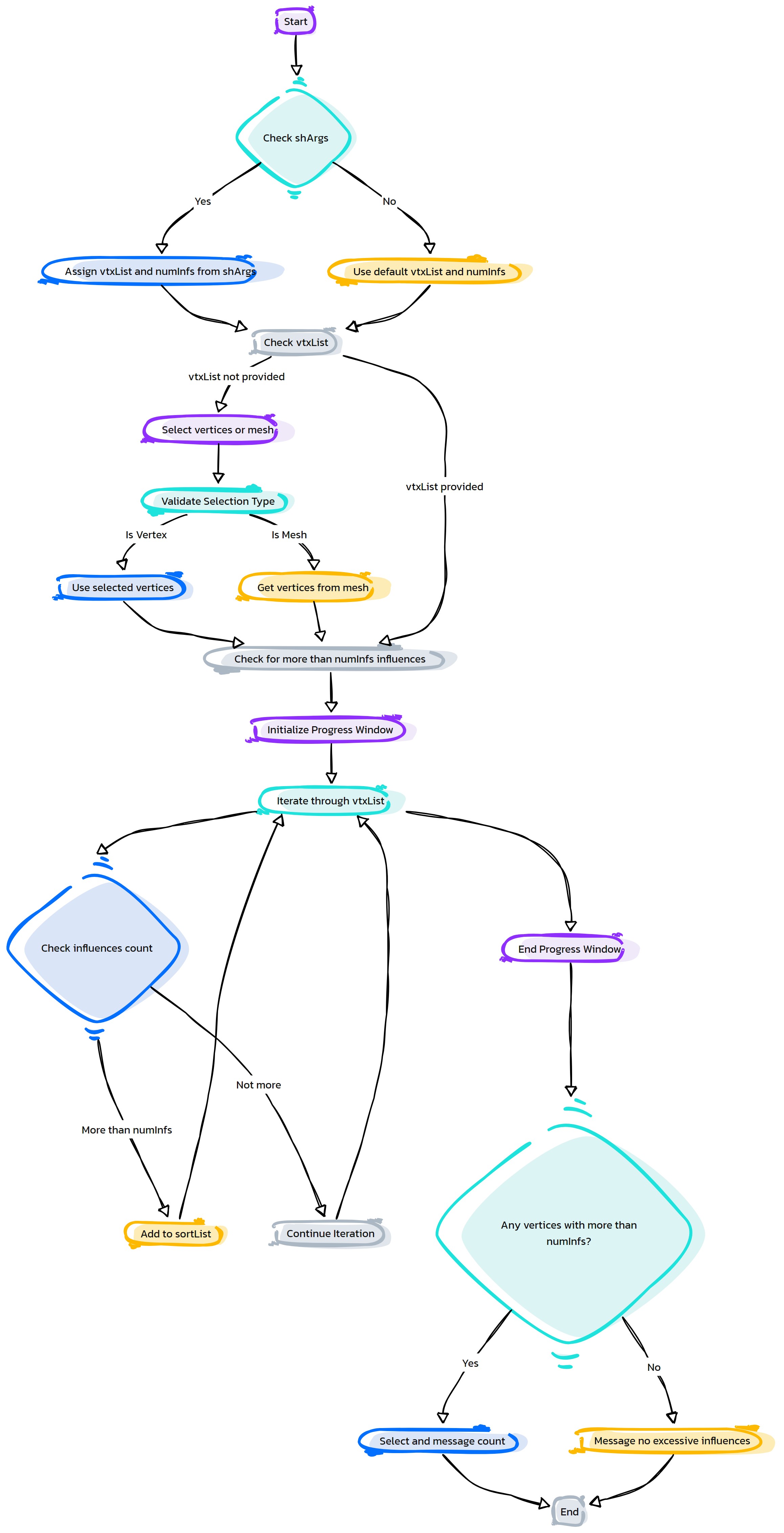
- HyperRig.importOrientJnts(self, useLocators=True, **shArgs)#
[shArgs: ]
Purpose:
:: Imports and orients joints based on locator positions in Autodesk Maya.
Used in rigging to orient joints accurately according to locator positions.
- Parameters:
useLocators – <bool> # Determines whether to use locators for joint orientation.
- Returns:
None # This function does not return any value but imports and orients joints.
Code Examples:
>>> use_locators = True
>>> importOrientJnts(useLocators=use_locators)
# Imports and orients joints based on locator positions.
graph TB Start[("fa:fa-play Start")] --> CheckUseLocators{"/fas:fa-question-circle Check Use Locators"} CheckUseLocators --"Using Locators"--> ImportPositionsAsLocators["/fas:fa-upload Import Positions as Locators"] CheckUseLocators --"Not Using Locators"--> ErrorNoLocators["/fas:fa-exclamation-triangle Error: No Locators"] ImportPositionsAsLocators --> SelectJointHierarchy{"/fas:fa-sitemap Select Joint Hierarchy"} SelectJointHierarchy --> ForEachJointInHierarchy{"/fas:fa-cogs For Each Joint in Hierarchy"} ForEachJointInHierarchy --> SnapPositionToLocator{"/fas:fa-map-pin Snap Position to Locator"} SnapPositionToLocator --> FreezeRotationValues{"/fas:fa-snowflake Freeze Rotation Values"} FreezeRotationValues --> OrientJointsToLocators{"/fas:fa-arrows-alt Orient Joints to Locators"} OrientJointsToLocators --> End[("fas:fa-stop-circle End")] ErrorNoLocators --> End style Start fill:#00cc00,stroke:#000,stroke-width:3px style CheckUseLocators fill:#f0ad4e,stroke:#000,stroke-width:2px style ImportPositionsAsLocators fill:#5bc0de,stroke:#000,stroke-width:2px style SelectJointHierarchy fill:#5cb85c,stroke:#000,stroke-width:2px style ForEachJointInHierarchy fill:#ffcc99,stroke:#000,stroke-width:2px style SnapPositionToLocator fill:#d9534f,stroke:#000,stroke-width:2px style FreezeRotationValues fill:#f0ad4e,stroke:#000,stroke-width:2px style OrientJointsToLocators fill:#5bc0de,stroke:#000,stroke-width:2px style End fill:#ff6666,stroke:#000,stroke-width:3px style ErrorNoLocators fill:#d9534f,stroke:#000,stroke-width:2px- Flow Chart Description:
This flowchart illustrates the importOrientJnts function:
The process begins by checking if locators are used for joint orientation.
If locators are used, positions are imported as locators.
If locators are not used, an error is displayed.
The joint hierarchy is selected for processing.
- For each joint in the hierarchy:
The joint’s position is snapped to its corresponding locator.
Rotation values are frozen to ensure proper orientation.
Joints are oriented based on the positions of their corresponding locators.
The process ends successfully after orienting all joints.
- HyperRig.keySelected(self, rangeList=[0, 90], **shArgs)#
[shArgs : rl=rangeList]
Purpose:
:: Sets keyframes on selected controllers within a specified range, useful in animation and rigging.
Automates the process of keying controllers, saving time and effort.
Allows for quick setup of animation tests and rig functionality checks.
Customizable range list facilitates flexibility in animation workflows.
- Parameters:
rangeList – <list> # The range of values for keying, default is [0, 90].
- Returns:
None # This function does not return a value but sets keyframes on selected controllers.
Code Examples:
>>> keySelected(rangeList=[0, 90])
# Sets keyframes on the selected controllers from 0 to 90.
graph TB Start[("fa:fa-play Start")] --> SelectControllers["/fas:fa-mouse-pointer Select Controllers"] SelectControllers --> RetrieveUserChannels{"/fas:fa-list Retrieve User Channels"} RetrieveUserChannels --"If User Channels Exist"--> KeySpecificChannels["/fas:fa-key Key Specific Channels"] RetrieveUserChannels --"If No User Channels"--> KeyAllChannels["/fas:fa-key Key All Channels"] KeySpecificChannels --> SetPlaybackOptions["/fas:fa-cog Set Playback Options"] KeyAllChannels --> SetPlaybackOptions SetPlaybackOptions --> SetKeyframes["/fas:fa-calendar-plus Set Keyframes"] SetKeyframes --> End[("fas:fa-stop End")] style Start fill:#00cc00,stroke:#000,stroke-width:3px style SelectControllers fill:#ffcc00,stroke:#000,stroke-width:2px style RetrieveUserChannels fill:#ff9999,stroke:#000,stroke-width:2px style KeySpecificChannels fill:#99ccff,stroke:#000,stroke-width:2px style KeyAllChannels fill:#cc99ff,stroke:#000,stroke-width:2px style SetPlaybackOptions fill:#99ff99,stroke:#000,stroke-width:2px style SetKeyframes fill:#ffcc99,stroke:#000,stroke-width:2px style End fill:#ff6666,stroke:#000,stroke-width:3px- Flow Chart Description:
This flowchart illustrates the keySelected function:
The process starts by selecting the controllers to keyframe.
- Retrieves user-defined channels from the Channel Box.
If specific channels are selected, keys are set for those channels.
If no specific channels are selected, keys are set for all available channels.
Sets playback options for the animation range.
Sets keyframes for the selected controllers within the specified range.
Completes the process and ends.
- HyperRig.message(self, messageTxt, **shArgs)#
[shArgs: ]
Purpose:
:: Displays a message to the user through a dialog window in Autodesk Maya.
Useful for providing feedback, warnings, or notifications to the user during scripting or tool usage.
- Parameters:
messageTxt – <str> # The message text to be displayed in the dialog window.
- Returns:
None # This function does not return any value but displays a message dialog.
Code Examples:
>>> message_text = "Operation completed successfully."
>>> message(messageTxt=message_text)
# Displays the specified message in a dialog window.
graph TB Start[("fa:fa-play Start")] --> CheckMessage{"fa:fa-comment Check Message"} CheckMessage --"If message is provided" --> ShowDialog["/fas:fa-window-restore Show Dialog"] ShowDialog --> End[("fas:fa-stop End")] style Start fill:#00cc00,stroke:#000,stroke-width:3px style CheckMessage fill:#ffcc00,stroke:#000,stroke-width:2px style ShowDialog fill:#ff9999,stroke:#000,stroke-width:2px style End fill:#ff6666,stroke:#000,stroke-width:3px- Flow Chart Description:
This flowchart illustrates the message function:
The process begins by checking if a message text is provided.
If the message text is available, it displays the message in a dialog window to the user.
The function then concludes without returning any value.
- HyperRig.moCap_RebuildSourceAnim(self, useLocators=False, **shArgs)#
[shArgs: ]
Purpose:
:: Rebuilds source animation data for a motion capture rig in Autodesk Maya.
Utilized in motion capture workflows to refine or adjust original animation data.
- Parameters:
useLocators – <bool> # Determines whether to use locators for rebuilding the animation.
- Returns:
None # This function does not return any value but rebuilds source animation for a mocap rig.
Code Examples:
>>> use_locators = False
>>> moCap_RebuildSourceAnim(useLocators=use_locators)
# Rebuilds source animation data for a motion capture rig.
graph TB Start[("fa:fa-play Start")] --> SelectTopNode{"/fas:fa-object-group Select Top Node"} SelectTopNode --> GetJointList{"/fas:fa-cubes Get Joint List"} GetJointList --> StartJointDuplication{"/fas:fa-spinner Start Joint Duplication"} StartJointDuplication --> ForEachJoint{"/fas:fa-cogs For Each Joint"} ForEachJoint --> DuplicateJoint{"/fas:fa-clone Duplicate Joint"} DuplicateJoint --> FreezeRotation{"/fas:fa-snowflake Freeze Rotation"} FreezeRotation --> ParentToOriginal{"/fas:fa-sitemap Parent To Original Joint"} ParentToOriginal --> ConstrainToOriginal{"/fas:fa-link Constrain to Original Joint"} ConstrainToOriginal --> AddToRebuildList{"/fas:fa-plus-square Add to Rebuild List"} AddToRebuildList --> EndJointDuplication{"/fas:fa-check-circle End Joint Duplication"} EndJointDuplication --> SelectRebuildJoints{"/fas:fa-hand-pointer Select Rebuild Joints"} SelectRebuildJoints --> SetPlaybackRange{"/fas:fa-hourglass-half Set Playback Range"} SetPlaybackRange --> BakeResults{"/fas:fa-cookie Bake Results"} BakeResults --> End[("fas:fa-stop-circle End")] style Start fill:#00cc00,stroke:#000,stroke-width:3px style SelectTopNode fill:#f0ad4e,stroke:#000,stroke-width:2px style GetJointList fill:#5bc0de,stroke:#000,stroke-width:2px style StartJointDuplication fill:#5cb85c,stroke:#000,stroke-width:2px style ForEachJoint fill:#ffcc99,stroke:#000,stroke-width:2px style DuplicateJoint fill:#d9534f,stroke:#000,stroke-width:2px style FreezeRotation fill:#f0ad4e,stroke:#000,stroke-width:2px style ParentToOriginal fill:#5bc0de,stroke:#000,stroke-width:2px style ConstrainToOriginal fill:#5cb85c,stroke:#000,stroke-width:2px style AddToRebuildList fill:#ffcc99,stroke:#000,stroke-width:2px style EndJointDuplication fill:#d9534f,stroke:#000,stroke-width:2px style SelectRebuildJoints fill:#f0ad4e,stroke:#000,stroke-width:2px style SetPlaybackRange fill:#5bc0de,stroke:#000,stroke-width:2px style BakeResults fill:#5cb85c,stroke:#000,stroke-width:2px style End fill:#ff6666,stroke:#000,stroke-width:3px- Flow Chart Description:
This flowchart illustrates the moCap_RebuildSourceAnim function:
The process begins with selecting the top node in the hierarchy.
Retrieves a list of joints from the selected top node.
Starts duplication of each joint in the list.
For each joint, duplicates the joint and freezes its rotation.
Parents the duplicated joint to the original joint’s parent.
Constrains the duplicated joint to the original joint.
Adds the duplicated joint to a list for rebuilding.
Completes the joint duplication process.
Selects all joints in the rebuild list.
Sets the playback range for baking results.
Bakes the results for the rebuild joints within the defined playback range.
Ends the function after successfully baking the results.
- HyperRig.moCap_UpdateJnts(self, **shArgs)#
[shArgs: ]
Purpose:
:: Updates joint positions based on a source prefix in Autodesk Maya, typically used in motion capture.
Essential for aligning and updating joint positions in mocap rigs to match source data or reference.
- Parameters:
srcPrefix – <str> # The source prefix used to identify the original joints for alignment.
- Returns:
None # This function does not return any value but updates joint positions based on the source prefix.
Code Examples:
>>> source_prefix = "Src_"
>>> moCap_UpdateJnts(srcPrefix=source_prefix)
# Updates joint positions based on the specified source prefix.
graph TB Start[("fa:fa-play Start")] --> GetSourcePrefix{"/fas:fa-tag Get Source Prefix"} GetSourcePrefix --> SelectJoints{"/fas:fa-hand-pointer Select Joints"} SelectJoints --> ForEachJoint{"/fas:fa-cogs For Each Joint"} ForEachJoint --> CheckTargetJoint{"/fas:fa-search Check Target Joint Exists"} CheckTargetJoint --"If Target Joint Exists"--> SnapPosition{"/fas:fa-arrows-alt Snap Position"} SnapPosition --> ConstrainParent{"/fas:fa-link Constrain to Parent"} CheckTargetJoint --"If Target Joint Does Not Exist"--> AddToMissingList{"/fas:fa-exclamation-triangle Add to Missing List"} AddToMissingList --> DisplayWarning{"/fas:fa-exclamation-triangle Display Warning"} ConstrainParent --> UpdateComplete{"/fas:fa-check-circle Update Complete"} DisplayWarning --> UpdateComplete UpdateComplete --> End[("fas:fa-stop-circle End")] style Start fill:#00cc00,stroke:#000,stroke-width:3px style GetSourcePrefix fill:#f0ad4e,stroke:#000,stroke-width:2px style SelectJoints fill:#5bc0de,stroke:#000,stroke-width:2px style ForEachJoint fill:#ffcc99,stroke:#000,stroke-width:2px style CheckTargetJoint fill:#d9534f,stroke:#000,stroke-width:2px style SnapPosition fill:#f0ad4e,stroke:#000,stroke-width:2px style ConstrainParent fill:#5bc0de,stroke:#000,stroke-width:2px style AddToMissingList fill:#ffcc99,stroke:#000,stroke-width:2px style DisplayWarning fill:#d9534f,stroke:#000,stroke-width:2px style UpdateComplete fill:#5cb85c,stroke:#000,stroke-width:2px style End fill:#ff6666,stroke:#000,stroke-width:3px- Flow Chart Description:
This flowchart illustrates the moCap_UpdateJnts function:
Retrieves the source prefix from the Maya UI.
Selects joints for the update process.
Iterates through each selected joint.
Checks if the target joint exists based on the source prefix.
If the target joint exists, snaps the position of the mocap joint to the target joint.
Constrains the mocap joint to the parent of the target joint.
If the target joint does not exist, adds the mocap joint to a missing list.
Displays a warning if any joints are missing.
Completes the update process after all joints have been processed.
Ends the function.
- HyperRig.moCap_VFX2GameRig(self, trgtPrefix='Rebuild_', **shArgs)#
[shArgs: ]
Purpose:
:: Converts a motion capture rig for VFX to a game-ready rig in Autodesk Maya.
Ideal for adapting motion capture data from high-resolution VFX rigs to more optimized game rigs.
- Parameters:
trgtPrefix – <str> # Prefix used for naming the rebuilt joints and nodes in the game rig.
- Returns:
None # This function does not return any value but converts a VFX rig to a game-ready rig.
Code Examples:
>>> target_prefix = "Rebuild_"
>>> moCap_VFX2GameRig(trgtPrefix=target_prefix)
# Converts a VFX motion capture rig to a game-ready rig.
graph TB Start[("fa:fa-play Start")] --> SelectTopGroup{"/fas:fa-object-group Select Top Group"} SelectTopGroup --> GetMeshList{"/fas:fa-cubes Get Mesh List"} GetMeshList --> StartSkinJointsProcessing{"/fas:fa-spinner Start Skin Joints Processing"} StartSkinJointsProcessing --> ForEachMeshInList{"/fas:fa-cogs For Each Mesh in List"} ForEachMeshInList --> CheckSkinJoints{"/fas:fa-search Check Skin Joints"} CheckSkinJoints --"If Skin Joints Exist"--> AddToSkinJointsSet{"/fas:fa-plus-square Add to Skin Joints Set"} AddToSkinJointsSet --> EndSkinJointsProcessing{"/fas:fa-check-circle End Skin Joints Processing"} EndSkinJointsProcessing --> SelectSkinJointsSet{"/fas:fa-hand-pointer Select Skin Joints Set"} SelectSkinJointsSet --> StartRebuildingJoints{"/fas:fa-sync-alt Start Rebuilding Joints"} StartRebuildingJoints --> ForEachJointInSet{"/fas:fa-cogs For Each Joint in Set"} ForEachJointInSet --> DuplicateAndPositionJoint{"/fas:fa-clone Duplicate and Position Joint"} DuplicateAndPositionJoint --> OpenAttributes{"/fas:fa-unlock Open Attributes"} OpenAttributes --> FreezeRotation{"/fas:fa-snowflake Freeze Rotation"} FreezeRotation --> ConstrainToOriginal{"/fas:fa-link Constrain to Original Joint"} ConstrainToOriginal --> EndRebuildingJoints{"/fas:fa-check-circle End Rebuilding Joints"} EndRebuildingJoints --> StartTransferringSkin{"/fas:fa-exchange-alt Start Transferring Skin"} StartTransferringSkin --> ForEachMeshInListAgain{"/fas:fa-cogs For Each Mesh in List"} ForEachMeshInListAgain --> CheckIfSkinned{"/fas:fa-question-circle Check If Skinned"} CheckIfSkinned --"If Mesh Is Skinned"--> TransferSkinWeights{"/fas:fa-balance-scale Transfer Skin Weights"} TransferSkinWeights --> ReparentNewJoints{"/fas:fa-sitemap Reparent New Joints"} ReparentNewJoints --> EndTransferringSkin{"/fas:fa-check-circle End Transferring Skin"} CheckIfSkinned --"If Mesh Is Not Skinned"--> EndTransferringSkin EndTransferringSkin --> End[("fas:fa-stop-circle End")] style Start fill:#00cc00,stroke:#000,stroke-width:3px style SelectTopGroup fill:#f0ad4e,stroke:#000,stroke-width:2px style GetMeshList fill:#5bc0de,stroke:#000,stroke-width:2px style StartSkinJointsProcessing fill:#5cb85c,stroke:#000,stroke-width:2px style ForEachMeshInList fill:#ffcc99,stroke:#000,stroke-width:2px style CheckSkinJoints fill:#d9534f,stroke:#000,stroke-width:2px style AddToSkinJointsSet fill:#f0ad4e,stroke:#000,stroke-width:2px style EndSkinJointsProcessing fill:#5bc0de,stroke:#000,stroke-width:2px style SelectSkinJointsSet fill:#5cb85c,stroke:#000,stroke-width:2px style StartRebuildingJoints fill:#ffcc99,stroke:#000,stroke-width:2px style ForEachJointInSet fill:#d9534f,stroke:#000,stroke-width:2px style DuplicateAndPositionJoint fill:#f0ad4e,stroke:#000,stroke-width:2px style OpenAttributes fill:#5bc0de,stroke:#000,stroke-width:2px style FreezeRotation fill:#5cb85c,stroke:#000,stroke-width:2px style ConstrainToOriginal fill:#ffcc99,stroke:#000,stroke-width:2px style EndRebuildingJoints fill:#d9534f,stroke:#000,stroke-width:2px style StartTransferringSkin fill:#f0ad4e,stroke:#000,stroke-width:2px style ForEachMeshInListAgain fill:#5bc0de,stroke:#000,stroke-width:2px style CheckIfSkinned fill:#5cb85c,stroke:#000,stroke-width:2px style TransferSkinWeights fill:#ffcc99,stroke:#000,stroke-width:2px style ReparentNewJoints fill:#d9534f,stroke:#000,stroke-width:2px style EndTransferringSkin fill:#f0ad4e,stroke:#000,stroke-width:2px style End fill:#ff6666,stroke:#000,stroke-width:3px- Flow Chart Description:
This flowchart illustrates the moCap_VFX2GameRig function:
Starts by selecting the top group in the hierarchy.
Retrieves a list of meshes in the group.
Processes each mesh to get skin joints and adds them to a skin joints set.
Selects the skin joints set and starts rebuilding joints for the game rig.
For each joint in the set, duplicates and positions the joint according to the original.
Opens attributes and freezes rotation for the new joints.
Constrains each new joint to its original counterpart.
Begins transferring skin weights from the original mesh to the new joints.
For each mesh, checks if it is skinned and transfers skin weights accordingly.
Reparents new joints to maintain hierarchy.
Concludes the skin transferring process and ends the function.
- HyperRig.moCap_defineSkeleton_HIK(self, **shArgs)#
[shArgs: ]
Purpose:
:: Defines a motion capture skeleton using HumanIK in Autodesk Maya.
Ideal for setting up motion capture data on a character rig.
- Returns:
None # This function does not return any value but sets up a HumanIK skeleton for motion capture.
Code Examples:
>>> moCap_defineSkeleton_HIK()
# Defines a motion capture skeleton using HumanIK.
graph TB Start[("fa:fa-play Start")] --> CheckSkeletonExistence{"/fas:fa-question-circle Check Skeleton Existence"} CheckSkeletonExistence --"Skeleton Exists"--> DefineSkeleton["/fas:fa-wrench Define Skeleton with HumanIK"] CheckSkeletonExistence --"Skeleton Does Not Exist"--> ErrorSkeletonNotFound["/fas:fa-exclamation-triangle Error: Skeleton Not Found"] DefineSkeleton --> SelectHierarchy{"/fas:fa-sitemap Select Hierarchy of Joints"} SelectHierarchy --"Hierarchy Selected"--> SetPlaybackOptions["/fas:fa-cogs Set Playback Options"] SetPlaybackOptions --> ResetRotationValues["/fas:fa-undo-alt Reset Rotation Values"] ResetRotationValues --> DefineHumanIKSkeleton{"/fas:fa-user-md Define HumanIK Skeleton"} DefineHumanIKSkeleton --> LockDefinition[("/fas:fa-lock Lock Definition")] LockDefinition --> End[("fas:fa-stop-circle End")] ErrorSkeletonNotFound --> End style Start fill:#00cc00,stroke:#000,stroke-width:3px style CheckSkeletonExistence fill:#f0ad4e,stroke:#000,stroke-width:2px style DefineSkeleton fill:#5bc0de,stroke:#000,stroke-width:2px style SelectHierarchy fill:#5cb85c,stroke:#000,stroke-width:2px style SetPlaybackOptions fill:#ffcc99,stroke:#000,stroke-width:2px style ResetRotationValues fill:#d9534f,stroke:#000,stroke-width:2px style DefineHumanIKSkeleton fill:#f0ad4e,stroke:#000,stroke-width:2px style LockDefinition fill:#5bc0de,stroke:#000,stroke-width:2px style End fill:#ff6666,stroke:#000,stroke-width:3px style ErrorSkeletonNotFound fill:#d9534f,stroke:#000,stroke-width:2px- Flow Chart Description:
This flowchart illustrates the moCap_defineSkeleton_HIK function:
The process begins by checking if a skeleton exists in the scene.
If no skeleton is found, an error message is displayed.
If a skeleton exists, the function defines the skeleton using HumanIK.
The hierarchy of joints is selected based on the top joint or group name.
Playback options are set to accommodate motion capture data.
Rotation values for all joints in the hierarchy are reset to zero.
The HumanIK skeleton is defined based on the selected hierarchy.
The HumanIK definition is locked, and the Character1 node is selected.
The process concludes successfully.
- HyperRig.moCap_fixElbowJnt(self, stJnt=None, skinMeshes=None, **shArgs)#
[shArgs: ]
Purpose:
:: Fixes elbow joint orientation in a motion capture rig in Autodesk Maya.
Used to correct common issues with elbow joint orientation in mocap rigs, ensuring accurate deformation.
- Parameters:
stJnt – <str> # The starting joint (usually shoulder) for the elbow correction.
skinMeshes – <list> # List of skinned meshes influenced by the elbow joint.
- Returns:
None # This function does not return any value but fixes the elbow joint orientation.
Code Examples:
>>> start_joint = "Shoulder_Jnt"
>>> skinned_meshes = ["Arm_Mesh"]
>>> moCap_fixElbowJnt(stJnt=start_joint, skinMeshes=skinned_meshes)
# Fixes the elbow joint orientation for the specified start joint and skinned meshes.
graph TB Start[("fa:fa-play Start")] --> CheckStartJoint{"/fas:fa-question-circle Check Start Joint"} CheckStartJoint --"If Start Joint Provided"--> UseProvidedStartJoint["/fas:fa-arrow-right Use Provided Start Joint"] CheckStartJoint --"If No Start Joint Provided"--> SelectStartJoint{"/fas:fa-hand-pointer Select Start Joint"} SelectStartJoint --"Select At Least One Joint"--> DefineStartJoint["/fas:fa-map-marker Define Start Joint"] UseProvidedStartJoint --> CheckSkinMeshes{"/fas:fa-question-circle Check Skin Meshes"} DefineStartJoint --> CheckSkinMeshes CheckSkinMeshes --"If Skin Meshes Provided"--> UseProvidedSkinMeshes["/fas:fa-arrow-right Use Provided Skin Meshes"] CheckSkinMeshes --"If No Skin Meshes Provided"--> SelectSkinMeshes{"/fas:fa-hand-pointer Select Skin Meshes"} SelectSkinMeshes --"Select At Least One Skinned Mesh"--> DefineSkinMeshes["/fas:fa-map-marker Define Skin Meshes"] UseProvidedSkinMeshes --> IdentifyElbowJoint{"/fas:fa-search Identify Elbow Joint"} DefineSkinMeshes --> IdentifyElbowJoint IdentifyElbowJoint --> CalculateDistances{"/fas:fa-ruler-combined Calculate Distances"} CalculateDistances --> DetermineReferenceLocation{"/fas:fa-map-marker-alt Determine Reference Location"} DetermineReferenceLocation --> OrientElbowJoint{"/fas:fa-sync-alt Orient Elbow Joint"} OrientElbowJoint --> DuplicateElbowJoint{"/fas:fa-clone Duplicate Elbow Joint"} DuplicateElbowJoint --> TransferSkinWeights{"/fas:fa-exchange-alt Transfer Skin Weights"} TransferSkinWeights --> ReattachChildJoints{"/fas:fa-link Reattach Child Joints"} ReattachChildJoints --> RenameAndDeleteOriginalElbow{"/fas:fa-trash-alt Rename And Delete Original Elbow"} RenameAndDeleteOriginalElbow --> End[("fas:fa-stop-circle End")] style Start fill:#00cc00,stroke:#000,stroke-width:3px style CheckStartJoint fill:#f0ad4e,stroke:#000,stroke-width:2px style UseProvidedStartJoint fill:#5bc0de,stroke:#000,stroke-width:2px style SelectStartJoint fill:#ffcc99,stroke:#000,stroke-width:2px style DefineStartJoint fill:#d9534f,stroke:#000,stroke-width:2px style CheckSkinMeshes fill:#f0ad4e,stroke:#000,stroke-width:2px style UseProvidedSkinMeshes fill:#5bc0de,stroke:#000,stroke-width:2px style SelectSkinMeshes fill:#ffcc99,stroke:#000,stroke-width:2px style DefineSkinMeshes fill:#d9534f,stroke:#000,stroke-width:2px style IdentifyElbowJoint fill:#5bc0de,stroke:#000,stroke-width:2px style CalculateDistances fill:#f0ad4e,stroke:#000,stroke-width:2px style DetermineReferenceLocation fill:#5bc0de,stroke:#000,stroke-width:2px style OrientElbowJoint fill:#ffcc99,stroke:#000,stroke-width:2px style DuplicateElbowJoint fill:#d9534f,stroke:#000,stroke-width:2px style TransferSkinWeights fill:#f0ad4e,stroke:#000,stroke-width:2px style ReattachChildJoints fill:#5bc0de,stroke:#000,stroke-width:2px style RenameAndDeleteOriginalElbow fill:#ffcc99,stroke:#000,stroke-width:2px style End fill:#ff6666,stroke:#000,stroke-width:3px- Flow Chart Description:
This flowchart illustrates the moCap_fixElbowJnt function:
Checks if a start joint is provided. If not, prompts to select a start joint.
Checks if skin meshes are provided. If not, prompts to select skin meshes.
Identifies the elbow and wrist joints based on the start joint.
Calculates distances between the start, elbow, and wrist joints.
Determines the reference location for elbow orientation.
Orients the elbow joint based on the reference location and joint axis.
Duplicates the elbow joint for maintaining the original orientation.
Transfers skin weights from the original elbow joint to the duplicate.
Reattaches child joints to the duplicated elbow joint.
Renames and deletes the original elbow joint, finalizing the correction.
Completes the elbow joint orientation correction process.
- HyperRig.moCap_manageEndJnts(self, action='add', removeInf=False, **shArgs)#
[shArgs: ]
Purpose:
:: Manages end joints in a motion capture rig in Autodesk Maya, such as adding, removing, or retrieving them.
Useful for optimizing mocap rigs by managing end joints, which often don’t contribute to deformation.
- Parameters:
action – <str> # Specifies the action to perform on end joints: ‘add’, ‘remove’, or ‘get’.
removeInf – <bool> # Determines whether to remove influences when removing end joints.
- Returns:
None or <list> # Returns a list of end joints if action is ‘get’, otherwise performs the specified action.
Code Examples:
>>> action = "add"
>>> moCap_manageEndJnts(action=action, removeInf=False)
# Manages end joints based on the specified action.
graph TB Start[("fa:fa-play Start")] --> CheckAction{"/fas:fa-question-circle Check Action"} CheckAction --"If Action is 'add'"--> AddEndJoints["/fas:fa-plus-circle Add End Joints"] CheckAction --"If Action is 'remove'"--> RemoveEndJoints{"/fas:fa-minus-circle Remove End Joints"} CheckAction --"If Action is 'get'"--> GetEndJoints{"/fas:fa-search Get End Joints"} AddEndJoints --> CheckSkinMesh["/fas:fa-search Check Skin Mesh"] CheckSkinMesh --"If Skin Mesh Provided"--> UseProvidedSkinMesh["/fas:fa-check-circle Use Provided Skin Mesh"] CheckSkinMesh --"If No Skin Mesh Provided"--> PromptForSkinMesh["/fas:fa-exclamation-triangle Prompt For Skin Mesh"] UseProvidedSkinMesh --> IdentifyEndJoints{"/fas:fa-search Identify End Joints"} PromptForSkinMesh --> IdentifyEndJoints IdentifyEndJoints --> AddNonSkinEndJoints{"/fas:fa-plus-circle Add Non-Skin End Joints"} AddNonSkinEndJoints --> End[("fas:fa-stop-circle End")] RemoveEndJoints --> CheckSkinMeshRemove["/fas:fa-search Check Skin Mesh"] CheckSkinMeshRemove --"If Skin Mesh Provided"--> UseProvidedSkinMeshRemove["/fas:fa-check-circle Use Provided Skin Mesh"] CheckSkinMeshRemove --"If No Skin Mesh Provided"--> PromptForSkinMeshRemove["/fas:fa-exclamation-triangle Prompt For Skin Mesh"] UseProvidedSkinMeshRemove --> IdentifyEndJointsRemove{"/fas:fa-search Identify End Joints"} PromptForSkinMeshRemove --> IdentifyEndJointsRemove IdentifyEndJointsRemove --> RemoveEndJointsAction{"/fas:fa-minus-circle Remove End Joints Action"} RemoveEndJointsAction --"If Remove Influence"--> RemoveInfluence["/fas:fa-trash-alt Remove Influence"] RemoveInfluence --> End RemoveEndJointsAction --"If Not Remove Influence"--> End GetEndJoints --> CheckSkinMeshGet["/fas:fa-search Check Skin Mesh"] CheckSkinMeshGet --"If Skin Mesh Provided"--> UseProvidedSkinMeshGet["/fas:fa-check-circle Use Provided Skin Mesh"] CheckSkinMeshGet --"If No Skin Mesh Provided"--> PromptForSkinMeshGet["/fas:fa-exclamation-triangle Prompt For Skin Mesh"] UseProvidedSkinMeshGet --> IdentifyEndJointsGet{"/fas:fa-search Identify End Joints"} PromptForSkinMeshGet --> IdentifyEndJointsGet IdentifyEndJointsGet --> RetrieveNonSkinEndJoints{"/fas:fa-arrow-circle-down Retrieve Non-Skin End Joints"} RetrieveNonSkinEndJoints --> End style Start fill:#00cc00,stroke:#000,stroke-width:3px style CheckAction fill:#f0ad4e,stroke:#000,stroke-width:2px style AddEndJoints fill:#5bc0de,stroke:#000,stroke-width:2px style RemoveEndJoints fill:#d9534f,stroke:#000,stroke-width:2px style GetEndJoints fill:#5cb85c,stroke:#000,stroke-width:2px style CheckSkinMesh fill:#f0ad4e,stroke:#000,stroke-width:2px style UseProvidedSkinMesh fill:#5bc0de,stroke:#000,stroke-width:2px style PromptForSkinMesh fill:#d9534f,stroke:#000,stroke-width:2px style IdentifyEndJoints fill:#5cb85c,stroke:#000,stroke-width:2px style AddNonSkinEndJoints fill:#5bc0de,stroke:#000,stroke-width:2px style CheckSkinMeshRemove fill:#f0ad4e,stroke:#000,stroke-width:2px style UseProvidedSkinMeshRemove fill:#5bc0de,stroke:#000,stroke-width:2px style PromptForSkinMeshRemove fill:#d9534f,stroke:#000,stroke-width:2px style IdentifyEndJointsRemove fill:#5cb85c,stroke:#000,stroke-width:2px style RemoveEndJointsAction fill:#d9534f,stroke:#000,stroke-width:2px style RemoveInfluence fill:#f0ad4e,stroke:#000,stroke-width:2px style CheckSkinMeshGet fill:#f0ad4e,stroke:#000,stroke-width:2px style UseProvidedSkinMeshGet fill:#5bc0de,stroke:#000,stroke-width:2px style PromptForSkinMeshGet fill:#d9534f,stroke:#000,stroke-width:2px style IdentifyEndJointsGet fill:#5cb85c,stroke:#000,stroke-width:2px style RetrieveNonSkinEndJoints fill:#5bc0de,stroke:#000,stroke-width:2px style End fill:#ff6666,stroke:#000,stroke-width:3px- Flow Chart Description:
This flowchart illustrates the moCap_manageEndJnts function:
Checks the specified action (‘add’, ‘remove’, or ‘get’) for managing end joints.
- If action is ‘add’:
Checks if a skin mesh is provided or prompts for it.
Identifies end joints and adds non-skin end joints.
- If action is ‘remove’:
Checks if a skin mesh is provided or prompts for it.
Identifies end joints and performs removal action, with option to remove influences.
- If action is ‘get’:
Checks if a skin mesh is provided or prompts for it.
Identifies end joints and retrieves non-skin end joints.
Completes the management process for end joints based on the specified action.
- HyperRig.props_CreateRig(self, **shArgs)#
[shArgs: ]
Purpose:
:: Creates a basic rigging setup for prop assets in Maya.
This function is used in rigging workflows to quickly set up a rig for static or non-deformable prop assets.
- Returns:
None # This function does not return any value but creates a basic rigging setup for selected prop assets.
Code Examples:
>>> props_CreateRig()
# Creates a rigging setup for the currently selected prop assets.
graph TB Start[("fa:fa-play Start")] --> SelectAssets{{"/fas:fa-mouse-pointer Select Assets"}} SelectAssets --"Selected Prop Assets"--> CreateHierarchy[("/fas:fa-sitemap Create Hierarchy")] CreateHierarchy --> CreateJoint[("/fas:fa-code-branch Create Joint")] CreateJoint --> ParentJoint[("/fas:fa-object-group Parent Joint to Group")] ParentJoint --> LoopAssets{{"/fas:fa-repeat Loop Through Assets"}} LoopAssets --"Asset is Mesh"--> SkinCluster[("/fas:fa-project-diagram Apply Skin Cluster")] LoopAssets --"Asset is Not Mesh"--> CheckMeshInChildren[("/fas:fa-search-plus Check for Mesh in Children")] CheckMeshInChildren --"Mesh Found in Children"--> SkinClusterInChildren[("/fas:fa-project-diagram Apply Skin Cluster to Children")] CheckMeshInChildren --"No Mesh in Children"--> NextAsset[("/fas:fa-arrow-right Next Asset")] SkinCluster --> NextAsset SkinClusterInChildren --> NextAsset NextAsset --"All Assets Processed"--> CreateVisibilitySwitch[("/fas:fa-eye Create Visibility Switch")] CreateVisibilitySwitch --> End[("fas:fa-stop-circle End")] style Start fill:#00cc00,stroke:#000,stroke-width:3px style SelectAssets fill:#ffcc00,stroke:#000,stroke-width:2px style CreateHierarchy fill:#ff9999,stroke:#000,stroke-width:2px style CreateJoint fill:#99ccff,stroke:#000,stroke-width:2px style ParentJoint fill:#5cb85c,stroke:#000,stroke-width:2px style LoopAssets fill:#f0ad4e,stroke:#000,stroke-width:2px style SkinCluster fill:#d9534f,stroke:#000,stroke-width:2px style CheckMeshInChildren fill:#5bc0de,stroke:#000,stroke-width:2px style SkinClusterInChildren fill:#d9534f,stroke:#000,stroke-width:2px style NextAsset fill:#f0ad4e,stroke:#000,stroke-width:2px style CreateVisibilitySwitch fill:#5cb85c,stroke:#000,stroke-width:2px style End fill:#ff6666,stroke:#000,stroke-width:3px- Flow Chart Description:
This flowchart illustrates the props_CreateRig function:
The process begins with selecting the prop assets in Maya.
A hierarchy is created to structure the rig components.
A joint, named ‘Prop_Jnt’, is created and parented to the ‘Joints_Grp’.
Each selected asset is processed. If it’s a mesh, a skin cluster is applied. If not, checks are made for mesh children and skin clusters applied accordingly.
A visibility switch is created for all processed assets and the ‘Global_Control’.
- HyperRig.refreshView(self, num, **shArgs)#
[shArgs: n=num]
Purpose:
:: Refreshes the Maya viewport a specified number of times.
Useful for updating the viewport to reflect changes in the scene, especially after running scripts or performing operations that alter the scene’s appearance.
- Parameters:
num – <int> # Number of times the Maya viewport will be refreshed.
- Returns:
None # This function does not return any value but refreshes the Maya viewport.
Code Examples:
>>> refresh_count = 5
>>> refreshView(refresh_count)
# Refreshes the Maya viewport 5 times.
graph TB Start[("fa:fa-play Start")] --> CheckArgs{{"/fas:fa-question Check Args"}} CheckArgs --"If shArgs provided" --> UpdateNum["/fas:fa-sync Update Num"] CheckArgs --"If shArgs not provided" --> RefreshLoop{"/fas:fa-sync-alt Refresh Loop"} UpdateNum --> RefreshLoop RefreshLoop --"For each refresh iteration" --> DoRefresh["/fas:fa-redo Do Refresh"] DoRefresh --"Loop until num is reached" --> RefreshLoop RefreshLoop --"When num is reached or not provided" --> End[("fas:fa-stop End")] style Start fill:#00cc00,stroke:#000,stroke-width:3px style CheckArgs fill:#ffcc00,stroke:#000,stroke-width:2px style UpdateNum fill:#99ccff,stroke:#000,stroke-width:2px style RefreshLoop fill:#ff9999,stroke:#000,stroke-width:2px style DoRefresh fill:#99ff99,stroke:#000,stroke-width:2px style End fill:#ff6666,stroke:#000,stroke-width:3px- Flow Chart Description:
This flowchart illustrates the refreshView function:
The process starts by checking if shArgs are provided and updating the num parameter as necessary.
A loop is initiated to refresh the Maya viewport the specified number of times.
The function concludes after completing the specified number of refresh iterations or if no number is provided.
- HyperRig.removeExpressions(self, keyWords=[], **shArgs)#
[shArgs : ]
Purpose:
:: Removes specific expression nodes from a Maya scene.
This function targets and deletes expression nodes that match the given keywords.
Useful for cleaning up scenes from potentially harmful or unwanted expressions.
Argument | Description :param keyWords: <list> #List of keywords to identify the expressions to be removed.
- Returns:
None #No return value, it removes specified expression nodes from the scene.
Code Examples:
>>> keyWords = ['rotate', 'translate']
>>> removeExpressions(keyWords)
graph TB Start[("fa:fa-play Start")] --> CheckKeywords{{"/fas:fa-search Check Keywords"}} CheckKeywords --"If keywords provided" --> GetExpressionNodes[("/fas:fa-code Get Expression Nodes by Keywords")] CheckKeywords --"If no keywords provided" --> GetAllExpressionNodes[("/fas:fa-code Get All Expression Nodes")] GetExpressionNodes --> DeleteNodes[("/fas:fa-trash Delete Nodes")] GetAllExpressionNodes --> DeleteNodes DeleteNodes --> DisplayInfo[("/fas:fa-info-circle Display Information")] DisplayInfo --> End[("fas:fa-stop End")] style Start fill:#00cc00,stroke:#000,stroke-width:3px style CheckKeywords fill:#f0ad4e,stroke:#000,stroke-width:2px style GetExpressionNodes fill:#5bc0de,stroke:#000,stroke-width:2px style GetAllExpressionNodes fill:#5bc0de,stroke:#000,stroke-width:2px style DeleteNodes fill:#d9534f,stroke:#000,stroke-width:2px style DisplayInfo fill:#5cb85c,stroke:#000,stroke-width:2px style End fill:#ff6666,stroke:#000,stroke-width:3px- Flow Chart Description:
This flowchart outlines the removeExpressions function:
The process starts by checking if any keyWords are provided.
If keyWords are provided, it retrieves expression nodes that match these keywords.
If no keyWords are provided, it fetches all expression nodes in the scene.
These expression nodes are then deleted from the scene.
Finally, information about the removed expression nodes is displayed.
- HyperRig.removeVirusNodes(self, removeAll=False, **shArgs)#
[shArgs : ]
Purpose:
:: Removes potentially harmful or unwanted script nodes from a Maya scene.
This function is designed to remove script nodes that may contain harmful scripts or unwanted elements.
It has an option to remove all script nodes or only those containing specific keywords.
- Parameters:
removeAll – <bool> #Flag to remove all script nodes if set to True.
- Returns:
None #No return value, it removes specified script nodes from the scene.
Code Examples:
>>> removeAll = True
>>> removeVirusNodes(removeAll)
graph TB Start[("fa:fa-play Start")] --> CheckRemoveAll{{"/fas:fa-question-circle Check Remove All Flag"}} CheckRemoveAll --"If removeAll is True" --> GetScriptNodesAll[("/fas:fa-code Get All Script Nodes")] CheckRemoveAll --"If removeAll is False" --> GetScriptNodesKey[("/fas:fa-key Get Script Nodes by Keywords")] GetScriptNodesAll --> DeleteNodes[("/fas:fa-trash Delete Nodes")] GetScriptNodesKey --> DeleteNodes DeleteNodes --> DisplayInfo[("/fas:fa-info-circle Display Information")] DisplayInfo --> End[("fas:fa-stop End")] style Start fill:#00cc00,stroke:#000,stroke-width:3px style CheckRemoveAll fill:#f0ad4e,stroke:#000,stroke-width:2px style GetScriptNodesAll fill:#5bc0de,stroke:#000,stroke-width:2px style GetScriptNodesKey fill:#5bc0de,stroke:#000,stroke-width:2px style DeleteNodes fill:#d9534f,stroke:#000,stroke-width:2px style DisplayInfo fill:#5cb85c,stroke:#000,stroke-width:2px style End fill:#ff6666,stroke:#000,stroke-width:3px- Flow Chart Description:
This flowchart depicts the removeVirusNodes function:
The process begins with checking the removeAll flag.
If removeAll is True, it retrieves all script nodes in the scene.
If removeAll is False, it fetches script nodes based on specific keywords like ‘gene’ and ‘vaccine’.
These script nodes are then deleted from the scene.
Finally, information about the removed script nodes is displayed.
- HyperRig.remove_ToesTemplate(self, **shArgs)#
[shArgs : ]
Purpose:
:: Removes toe templates from a foot rig in Autodesk Maya.
This function deletes toe templates based on the specified foot name prefix.
It is used to clean up or modify existing toe rig setups.
- Parameters:
toesPrefix – <str> #Prefix for the foot name from which toe templates are removed.
- Returns:
None #No return value, it removes toe templates from the specified foot rig.
Code Examples:
>>> toesPrefix = 'Foot'
>>> remove_ToesTemplate()
graph TB Start[("fa:fa-play Start")] --> CheckPrefix{{"/fas:fa-question Check Foot Prefix"}} CheckPrefix --"If toesPrefix is provided" --> GetToeControls["/fas:fa-cogs Get Toe Controls"] CheckPrefix --"If toesPrefix is not provided" --> End[("fas:fa-stop End")] GetToeControls --> CheckCurvesExistence{{"/fas:fa-search Check Curves Existence"}} CheckCurvesExistence --"If toe curves exist" --> DeleteToeCurves[("/fas:fa-trash-alt Delete Toe Curves")] CheckCurvesExistence --"If toe curves do not exist" --> End DeleteToeCurves --> DeleteToeControls[("/fas:fa-trash-alt Delete Toe Controls")] DeleteToeControls --> DeleteToeBones[("/fas:fa-trash-alt Delete Toe Bones")] DeleteToeBones --> End style Start fill:#00cc00,stroke:#000,stroke-width:3px style CheckPrefix fill:#ffcc00,stroke:#000,stroke-width:2px style GetToeControls fill:#5bc0de,stroke:#000,stroke-width:2px style CheckCurvesExistence fill:#ffcc00,stroke:#000,stroke-width:2px style DeleteToeCurves fill:#d9534f,stroke:#000,stroke-width:2px style DeleteToeControls fill:#d9534f,stroke:#000,stroke-width:2px style DeleteToeBones fill:#d9534f,stroke:#000,stroke-width:2px style End fill:#ff6666,stroke:#000,stroke-width:3px- Flow Chart Description:
This flowchart illustrates the remove_ToesTemplate function:
The process starts by checking if a toesPrefix is provided.
Retrieves control nodes related to toes based on the prefix.
Checks if toe curves exist for the specified prefix.
If curves exist, it deletes the toe curves, controls, and bones associated with the toes.
The process ends once all the toe-related nodes are removed.
- HyperRig.renameShapesHR(self, selList=None, renameOrigNodes=False, **shArgs)#
[shArgs : sl=selList, ron=renameOrigNodes]
Purpose:
:: Renames shape nodes to match their respective transform nodes, simplifying scene hierarchy and readability.
Essential for maintaining a clear and organized scene, especially in complex rigs.
Helps in easily identifying corresponding shape nodes for transforms.
Can optionally rename original nodes, ensuring consistency throughout the hierarchy.
- Parameters:
selList – <list, optional> # The list of objects whose shape nodes are to be renamed. If not provided, uses the selected objects.
renameOrigNodes – <bool> # Whether to also rename the original nodes.
- Returns:
None # This function does not return a value but renames shape nodes.
Code Examples:
>>> renameShapesHR(selList=['obj1', 'obj2'], renameOrigNodes=True)
# Renames shape nodes and original nodes of the specified objects.
graph TB Start[("fa:fa-play Start")] --> SelectObjects["/fas:fa-mouse-pointer Select Objects"] SelectObjects --> RenameShapes{"/fas:fa-text-height Rename Shapes"} RenameShapes --"If Renaming Original Nodes"--> RenameOrigNodes["/fas:fa-sync-alt Rename Original Nodes"] RenameShapes --"If Not Renaming Original Nodes"--> RenameShapeNodes["/fas:fa-i-cursor Rename Shape Nodes"] RenameOrigNodes --> End[("fas:fa-stop End")] RenameShapeNodes --> End style Start fill:#00cc00,stroke:#000,stroke-width:3px style SelectObjects fill:#ffcc00,stroke:#000,stroke-width:2px style RenameShapes fill:#ff9999,stroke:#000,stroke-width:2px style RenameOrigNodes fill:#99ccff,stroke:#000,stroke-width:2px style RenameShapeNodes fill:#cc99ff,stroke:#000,stroke-width:2px style End fill:#ff6666,stroke:#000,stroke-width:3px- Flow Chart Description:
This flowchart illustrates the renameShapesHR function:
The process starts by selecting objects for renaming shape nodes.
- Checks if the option to rename original nodes is enabled.
If enabled, renames both original and shape nodes to match the transform nodes.
If not enabled, only renames shape nodes to match their corresponding transform nodes.
Completes the renaming process and ends.
- HyperRig.selectCVs(self, **shArgs)#
[shArgs: ]
Purpose:
:: Selects the control vertices (CVs) of the currently selected NURBS curves or surfaces in Maya.
This function is commonly used in rigging and animation workflows for fine-tuning curve or surface shapes.
- Returns:
None # This function does not return any value but selects CVs of the selected NURBS curves or surfaces.
Code Examples:
>>> selectCVs()
# Selects the CVs of currently selected NURBS curves or surfaces.
graph TB Start[("fa:fa-play Start")] --> GetSelected{"fas:fa-mouse-pointer Get Selected NURBS"} GetSelected --"For each selected NURBS" --> GetCVs["fas:fa-bezier-curve Get CVs"] GetCVs --"Retrieve CVs of each NURBS" --> StoreCVs["/fas:fa-save Store CVs"] StoreCVs --"Store all CVs in list" --> SelectCVs["/fas:fa-hand-pointer Select CVs"] SelectCVs --> End[("fas:fa-stop End")] style Start fill:#00cc00,stroke:#000,stroke-width:3px style GetSelected fill:#ffcc00,stroke:#000,stroke-width:2px style GetCVs fill:#99ccff,stroke:#000,stroke-width:2px style StoreCVs fill:#ff9999,stroke:#000,stroke-width:2px style SelectCVs fill:#99ff99,stroke:#000,stroke-width:2px style End fill:#ff6666,stroke:#000,stroke-width:3px- Flow Chart Description:
This flowchart illustrates the selectCVs function:
The process begins by obtaining all currently selected NURBS curves or surfaces.
For each selected NURBS, control vertices (CVs) are retrieved.
The CVs of all selected NURBS are stored in a list.
Finally, all the CVs in the list are selected, enabling further manipulations or adjustments.
- HyperRig.shiftCtrlShapes(self, shiftType='r', valList=[0, 90, 0], **shArgs)#
[shArgs: st=shiftType, vl=valList]
Purpose:
:: Shifts the control shapes of the selected controls in Maya based on specified parameters.
Ideal for adjusting control shapes in rigging, without affecting their functionality.
- Parameters:
shiftType – <str> # Type of shift operation, e.g., ‘r’ for rotation.
valList – <list> # Values for the shift operation, e.g., [0, 90, 0] for rotation.
- Returns:
None # This function does not return any value but shifts control shapes.
Code Examples:
>>> shift_type = 'r'
>>> values = [0, 90, 0]
>>> shiftCtrlShapes(shift_type, values)
# Rotates the control shapes of selected controls by 90 degrees around the Y-axis.
graph TB Start[("fa:fa-play Start")] --> CheckShArgs{{"/fas:fa-question Check shArgs"}} CheckShArgs --"shArgs provided"--> UpdateArgs[("/fas:fa-sync-alt Update Arguments")] CheckShArgs --"shArgs not provided"--> GetSelection{{"/fas:fa-mouse-pointer Get Selection"}} UpdateArgs --> ShiftCtrls[("/fas:fa-exchange-alt Shift Controls")] GetSelection --> ShiftCtrls ShiftCtrls --> End[("fas:fa-stop-circle End")] style Start fill:#00cc00,stroke:#000,stroke-width:3px style CheckShArgs fill:#ffcc00,stroke:#000,stroke-width:2px style UpdateArgs fill:#ff9999,stroke:#000,stroke-width:2px style GetSelection fill:#99ccff,stroke:#000,stroke-width:2px style ShiftCtrls fill:#5cb85c,stroke:#000,stroke-width:2px style End fill:#ff6666,stroke:#000,stroke-width:3px- Flow Chart Description:
This flowchart illustrates the shiftCtrlShapes function:
The process starts by checking if shArgs are provided and updates arguments if necessary.
If shArgs are not provided, the function retrieves the current selection of controls.
It then shifts the control shapes based on the specified shift type (e.g., rotation) and values (e.g., [0, 90, 0]).
- HyperRig.transfer_SDKs(self, src=None, dest=None, **shArgs)#
[shArgs: s=src, d=dest]
Purpose:
:: Transfers Set Driven Key (SDK) animations from a source control to a destination control in Maya.
This function is useful in rigging workflows when needing to replicate SDK animations across multiple controls.
- Parameters:
src – <str/PyNode> # The source control with existing SDK animations.
dest – <str/PyNode> # The destination control where SDK animations will be transferred.
- Returns:
None # This function does not return any value but transfers SDK animations.
Code Examples:
>>> source_ctrl = "sourceControl"
>>> destination_ctrl = "destinationControl"
>>> transfer_SDKs(source_ctrl, destination_ctrl)
# Transfers SDKs from 'sourceControl' to 'destinationControl'.
graph TB Start[("fa:fa-play Start")] --> CheckShArgs{{"/fas:fa-question Check shArgs"}} CheckShArgs --"shArgs provided"--> UpdateArgs[("/fas:fa-sync-alt Update Arguments")] CheckShArgs --"shArgs not provided"--> SelectNodes{{"/fas:fa-mouse-pointer Select Nodes"}} UpdateArgs --> TransferSDKs[("/fas:fa-exchange-alt Transfer SDKs")] SelectNodes --> TransferSDKs TransferSDKs --> End[("fas:fa-stop-circle End")] style Start fill:#00cc00,stroke:#000,stroke-width:3px style CheckShArgs fill:#ffcc00,stroke:#000,stroke-width:2px style UpdateArgs fill:#ff9999,stroke:#000,stroke-width:2px style SelectNodes fill:#99ccff,stroke:#000,stroke-width:2px style TransferSDKs fill:#5cb85c,stroke:#000,stroke-width:2px style End fill:#ff6666,stroke:#000,stroke-width:3px- Flow Chart Description:
This flowchart illustrates the transfer_SDKs function:
The process begins by checking if shArgs are provided and updates arguments if necessary.
If shArgs are not provided, the function requires the user to select the source and destination nodes.
SDK animations are then transferred from the source control to the destination control.
- HyperRig.tyrePressureCtrl(self, divCount=10, selList=None, bsGrp='BlendShapes_Grp', **shArgs)#
[shArgs: dc=divCount, sl=selList, bg=bsGrp]
Purpose:
:: Creates a tyre pressure control system in Maya using lattice deformers and blend shapes.
Useful in rigging vehicles or objects with tyres that need to simulate pressure or deformation effects.
- Parameters:
divCount – <int> # Division count for the lattice deformer.
selList – <list> # List of objects to apply the tyre pressure control system.
bsGrp – <str> # Name of the blend shape group.
- Returns:
None # This function does not return any value but sets up a tyre pressure control system.
Code Examples:
>>> division_count = 10
>>> selected_objects = ['tyre1', 'tyre2']
>>> blend_shape_group = 'BlendShapes_Group'
>>> tyrePressureCtrl(division_count, selected_objects, blend_shape_group)
# Sets up a tyre pressure control system for 'tyre1' and 'tyre2'.
graph TB Start[("fa:fa-play Start")] --> CheckShArgs{{"/fas:fa-question Check shArgs"}} CheckShArgs --"shArgs provided"--> UpdateArgs[("/fas:fa-sync-alt Update Arguments")] CheckShArgs --"shArgs not provided"--> SelectNodes{{"/fas:fa-mouse-pointer Select Nodes"}} UpdateArgs --> SetupTyrePressureCtrl[("/fas:fa-car-side Setup Tyre Pressure Control")] SelectNodes --> SetupTyrePressureCtrl SetupTyrePressureCtrl --> End[("fas:fa-stop-circle End")] style Start fill:#00cc00,stroke:#000,stroke-width:3px style CheckShArgs fill:#ffcc00,stroke:#000,stroke-width:2px style UpdateArgs fill:#ff9999,stroke:#000,stroke-width:2px style SelectNodes fill:#99ccff,stroke:#000,stroke-width:2px style SetupTyrePressureCtrl fill:#5cb85c,stroke:#000,stroke-width:2px style End fill:#ff6666,stroke:#000,stroke-width:3px- Flow Chart Description:
This flowchart illustrates the tyrePressureCtrl function:
Begins by checking if shArgs are provided and updates the arguments accordingly.
If shArgs are not provided, the user is required to select the animation control and the mesh for the tyre pressure system.
The process then sets up a tyre pressure control system using lattice deformers and blend shapes.
- HyperRig.update_ClusterInfo_FL(self, **shArgs)#
[shArgs: ]
Purpose:
:: Toggles the visibility of the Cluster Information frame layout in the as_HyperRig UI.
This function is used to dynamically adjust the UI based on user interaction, specifically for displaying or hiding cluster information.
- Returns:
None # This function does not return any value but updates the UI layout of as_HyperRig.
Code Examples:
>>> update_ClusterInfo_FL()
# Toggles the visibility of the Cluster Information section in the as_HyperRig UI.
graph TB Start[("fa:fa-play Start")] --> QueryFLState{{"fas:fa-question Query FrameLayout State"}} QueryFLState --"If FrameLayout is collapsed" --> ExpandFL["/fas:fa-expand-arrows-alt Expand FrameLayout"] ExpandFL --> UpdateWindowSize1["/fas:fa-window-maximize Update Window Size"] QueryFLState --"If FrameLayout is expanded" --> CollapseFL["/fas:fa-compress-arrows-alt Collapse FrameLayout"] CollapseFL --> UpdateWindowSize2["/fas:fa-window-minimize Update Window Size"] UpdateWindowSize1 --> End[("fas:fa-stop End")] UpdateWindowSize2 --> End style Start fill:#00cc00,stroke:#000,stroke-width:3px style QueryFLState fill:#ffcc00,stroke:#000,stroke-width:2px style ExpandFL fill:#99ff99,stroke:#000,stroke-width:2px style CollapseFL fill:#99ccff,stroke:#000,stroke-width:2px style UpdateWindowSize1 fill:#ff9999,stroke:#000,stroke-width:2px style UpdateWindowSize2 fill:#ff9999,stroke:#000,stroke-width:2px style End fill:#ff6666,stroke:#000,stroke-width:3px- Flow Chart Description:
This flowchart illustrates the update_ClusterInfo_FL function:
The function begins by querying the current state of the Cluster Information frame layout in the as_HyperRig UI.
If the frame layout is collapsed, it is expanded and the window size is updated accordingly.
If the frame layout is already expanded, it is collapsed, and the window size is adjusted to reflect the change.
- HyperRig.update_CreateClust_FL(self, **shArgs)#
[shArgs: ]
Purpose:
:: Toggles the visibility and adjusts the size of the Create Cluster frame layout in the as_HyperRig UI.
This function is used to dynamically adjust the UI based on user interaction, specifically for the Create Cluster section.
- Returns:
None # This function does not return any value but updates the UI layout of as_HyperRig.
Code Examples:
>>> update_CreateClust_FL()
# Toggles the visibility and size of the Create Cluster section in the as_HyperRig UI.
graph TB Start[("fa:fa-play Start")] --> QueryFLState{{"fas:fa-question Query FrameLayout State"}} QueryFLState --"If FrameLayout is collapsed" --> ExpandFL["/fas:fa-expand-arrows-alt Expand FrameLayout"] ExpandFL --> UpdateWindowSize1["/fas:fa-window-maximize Update Window Size"] QueryFLState --"If FrameLayout is expanded" --> CollapseFL["/fas:fa-compress-arrows-alt Collapse FrameLayout"] CollapseFL --> UpdateWindowSize2["/fas:fa-window-minimize Update Window Size"] UpdateWindowSize1 --> End[("fas:fa-stop End")] UpdateWindowSize2 --> End style Start fill:#00cc00,stroke:#000,stroke-width:3px style QueryFLState fill:#ffcc00,stroke:#000,stroke-width:2px style ExpandFL fill:#99ff99,stroke:#000,stroke-width:2px style CollapseFL fill:#99ccff,stroke:#000,stroke-width:2px style UpdateWindowSize1 fill:#ff9999,stroke:#000,stroke-width:2px style UpdateWindowSize2 fill:#ff9999,stroke:#000,stroke-width:2px style End fill:#ff6666,stroke:#000,stroke-width:3px- Flow Chart Description:
This flowchart illustrates the update_CreateClust_FL function:
The function starts by checking the state of the Create Cluster frame layout in the as_HyperRig UI.
If the frame layout is collapsed, it is expanded and the window size is adjusted downwards.
Conversely, if the frame layout is expanded, it is collapsed, resulting in an upward adjustment of the window size.
- HyperRig.update_EditClust_FL(self, **shArgs)#
[shArgs: ]
Purpose:
:: Toggles the visibility and adjusts the size of the Edit Cluster frame layout in the as_HyperRig UI.
This function is used to dynamically adjust the UI based on user interaction, specifically for the Edit Cluster section.
- Returns:
None # This function does not return any value but updates the UI layout of as_HyperRig.
Code Examples:
>>> update_EditClust_FL()
# Toggles the visibility and size of the Edit Cluster section in the as_HyperRig UI.
graph TB Start[("fa:fa-play Start")] --> QueryFLState{{"fas:fa-question Query FrameLayout State"}} QueryFLState --"If FrameLayout is collapsed" --> ExpandFL["/fas:fa-expand-arrows-alt Expand FrameLayout"] ExpandFL --> UpdateWindowSize1["/fas:fa-window-maximize Update Window Size"] QueryFLState --"If FrameLayout is expanded" --> CollapseFL["/fas:fa-compress-arrows-alt Collapse FrameLayout"] CollapseFL --> UpdateWindowSize2["/fas:fa-window-minimize Update Window Size"] UpdateWindowSize1 --> End[("fas:fa-stop End")] UpdateWindowSize2 --> End style Start fill:#00cc00,stroke:#000,stroke-width:3px style QueryFLState fill:#ffcc00,stroke:#000,stroke-width:2px style ExpandFL fill:#99ff99,stroke:#000,stroke-width:2px style CollapseFL fill:#99ccff,stroke:#000,stroke-width:2px style UpdateWindowSize1 fill:#ff9999,stroke:#000,stroke-width:2px style UpdateWindowSize2 fill:#ff9999,stroke:#000,stroke-width:2px style End fill:#ff6666,stroke:#000,stroke-width:3px- Flow Chart Description:
This flowchart illustrates the update_EditClust_FL function:
The function begins by querying the state of the Edit Cluster frame layout in the as_HyperRig UI.
If the frame layout is collapsed, it is expanded, and the window size is adjusted accordingly.
If the frame layout is expanded, it is collapsed, leading to a corresponding adjustment in the window size.
- HyperRig.update_HairSystems(self, optionMenu, **shArgs)#
[shArgs: om=optionMenu]
Purpose:
:: Updates the hair systems list in the specified options menu within the as_HyperRig UI.
Used to refresh the list of hair systems available for selection, ensuring the UI reflects the current scene state.
- Parameters:
optionMenu – <str> # Name of the option menu to update with hair system names.
- Returns:
None # This function does not return any value but updates the specified option menu with current hair systems.
Code Examples:
>>> option_menu_name = "hairSystemsMenu"
>>> update_HairSystems(option_menu_name)
# Updates the specified hair systems menu with the latest hair systems in the scene.
graph TB Start[("fa:fa-play Start")] --> CheckOptionMenu{{"/fas:fa-bars Check Option Menu"}} CheckOptionMenu --"Option Menu Exists"--> ListHairSystems[("/fas:fa-list List Hair Systems")] CheckOptionMenu --"No Option Menu"--> End[("fas:fa-stop-circle End")] ListHairSystems --> GetMenuItems[("/fas:fa-tasks Get Menu Items")] GetMenuItems --> CheckHairSystems{{"/fas:fa-check-square Check Hair Systems"}} CheckHairSystems --"Hair Systems Available"--> LoopThroughHairSystems{{"/fas:fa-sync Loop Through Hair Systems"}} LoopThroughHairSystems --> AddMenuItem[("/fas:fa-plus-square Add Menu Item")] AddMenuItem --> End CheckHairSystems --"No Hair Systems"--> End style Start fill:#00cc00,stroke:#000,stroke-width:3px style CheckOptionMenu fill:#ffcc00,stroke:#000,stroke-width:2px style ListHairSystems fill:#5cb85c,stroke:#000,stroke-width:2px style GetMenuItems fill:#f0ad4e,stroke:#000,stroke-width:2px style CheckHairSystems fill:#d9534f,stroke:#000,stroke-width:2px style LoopThroughHairSystems fill:#5bc0de,stroke:#000,stroke-width:2px style AddMenuItem fill:#99ccff,stroke:#000,stroke-width:2px style End fill:#ff6666,stroke:#000,stroke-width:3px- Flow Chart Description:
This flowchart illustrates the update_HairSystems function:
The function begins by checking if the specified option menu exists in the UI.
If the option menu is found, it lists all hair systems available in the Maya scene.
The menu items in the option menu are then retrieved.
The function checks if there are any hair systems available.
For each hair system not already in the menu, a new menu item is added.
The process ends after updating the option menu with all current hair systems.
- HyperRig.update_RigInfo_FL(self, **shArgs)#
[shArgs: ]
Purpose:
:: Toggles the visibility of the Rig Information frame layout in the as_HyperRig UI.
This function is used to dynamically adjust the UI based on user interaction, specifically for displaying or hiding rig information.
- Returns:
None # This function does not return any value but updates the UI layout of as_HyperRig.
Code Examples:
>>> update_RigInfo_FL()
# Toggles the visibility of the Rig Information section in the as_HyperRig UI.
graph TD Start[("fa:fa-play Start")] --> GetFrameLayoutState{"/fas:fa-question-circle Get FrameLayout State"} GetFrameLayoutState --"Check if FrameLayout is Closed"--> OpenFrameLayout["/fas:fa-toggle-on Open FrameLayout"] GetFrameLayoutState --"Check if FrameLayout is Open"--> CloseFrameLayout["/fas:fa-toggle-off Close FrameLayout"] OpenFrameLayout --> UpdateUILayout["/fas:fa-pencil-alt Update UI Layout"] CloseFrameLayout --> UpdateUILayout UpdateUILayout --"Update UI Layout"--> End["/fas:fa-stop End"] style Start fill:#00cc00,stroke:#000,stroke-width:3px style GetFrameLayoutState fill:#ffcc00,stroke:#000,stroke-width:2px style OpenFrameLayout fill:#ccffcc,stroke:#000,stroke-width:2px style CloseFrameLayout fill:#ff9999,stroke:#000,stroke-width:2px style UpdateUILayout fill:#99ccff,stroke:#000,stroke-width:2px style End fill:#ff6666,stroke:#000,stroke-width:3px- Flow Chart Description:
This flowchart illustrates the update_RigInfo_FL function:
Checks the current state of the Rig Information frame layout.
If the frame layout is closed, it opens it and updates the UI layout accordingly.
If the frame layout is open, it closes it and updates the UI layout accordingly.
Ends the process.
- HyperRig.update_WorkboxPaint_FL(self, **shArgs)#
[shArgs: ]
Purpose:
:: Toggles the visibility and adjusts the size of the Workbox Paint frame layout in the as_HyperRig UI.
This function is utilized to dynamically adjust the UI based on user interaction, specifically for the Workbox Paint section.
- Returns:
None # This function does not return any value but updates the UI layout of as_HyperRig.
Code Examples:
>>> update_WorkboxPaint_FL()
# Toggles the visibility and size of the Workbox Paint section in the as_HyperRig UI.
graph TD Start[("fa:fa-play Start")] --> GetFrameLayoutState{"/fas:fa-question-circle Get FrameLayout State"} GetFrameLayoutState --"Check if FrameLayout is Closed"--> OpenFrameLayout["/fas:fa-toggle-on Open FrameLayout"] GetFrameLayoutState --"Check if FrameLayout is Open"--> CloseFrameLayout["/fas:fa-toggle-off Close FrameLayout"] OpenFrameLayout --> UpdateUILayout["/fas:fa-pencil-alt Update UI Layout"] CloseFrameLayout --> UpdateUILayout UpdateUILayout --"Update UI Layout"--> End["/fas:fa-stop End"] style Start fill:#00cc00,stroke:#000,stroke-width:3px style GetFrameLayoutState fill:#ffcc00,stroke:#000,stroke-width:2px style OpenFrameLayout fill:#ccffcc,stroke:#000,stroke-width:2px style CloseFrameLayout fill:#ff9999,stroke:#000,stroke-width:2px style UpdateUILayout fill:#99ccff,stroke:#000,stroke-width:2px style End fill:#ff6666,stroke:#000,stroke-width:3px- Flow Chart Description:
This flowchart outlines the update_WorkboxPaint_FL function:
Checks the current state of the Workbox Paint frame layout.
If the frame layout is closed, it opens it and adjusts the UI layout accordingly.
If the frame layout is open, it closes it and adjusts the UI layout accordingly.
Ends the process.
- HyperRig.update_meshInfo_FL(self, **shArgs)#
[shArgs: ]
Purpose:
:: Toggles the visibility of the Mesh Information frame layout in the as_HyperRig UI.
This function is used to dynamically adjust the UI based on user interaction, specifically for displaying or hiding mesh information.
- Returns:
None # This function does not return any value but updates the UI layout of as_HyperRig.
Code Examples:
>>> update_meshInfo_FL()
# Toggles the visibility of the Mesh Information section in the as_HyperRig UI.
graph TB Start[("fa:fa-play Start")] --> QueryFLState{{"fas:fa-question Query FrameLayout State"}} QueryFLState --"If FrameLayout is collapsed" --> ExpandFL["/fas:fa-expand-arrows-alt Expand FrameLayout"] ExpandFL --> UpdateWindowSize1["/fas:fa-window-maximize Update Window Size"] QueryFLState --"If FrameLayout is expanded" --> CollapseFL["/fas:fa-compress-arrows-alt Collapse FrameLayout"] CollapseFL --> UpdateWindowSize2["/fas:fa-window-minimize Update Window Size"] UpdateWindowSize1 --> End[("fas:fa-stop End")] UpdateWindowSize2 --> End style Start fill:#00cc00,stroke:#000,stroke-width:3px style QueryFLState fill:#ffcc00,stroke:#000,stroke-width:2px style ExpandFL fill:#99ff99,stroke:#000,stroke-width:2px style CollapseFL fill:#99ccff,stroke:#000,stroke-width:2px style UpdateWindowSize1 fill:#ff9999,stroke:#000,stroke-width:2px style UpdateWindowSize2 fill:#ff9999,stroke:#000,stroke-width:2px style End fill:#ff6666,stroke:#000,stroke-width:3px- Flow Chart Description:
This flowchart illustrates the update_meshInfo_FL function:
The function starts by checking the current state of the Mesh Information frame layout in the as_HyperRig UI.
If the frame layout is collapsed, the function expands it and adjusts the window size to accommodate the change.
Conversely, if the frame layout is expanded, it collapses the layout and modifies the window size accordingly.