
eSpec#
eSpec Features
:Advanced Specific Functions Module:
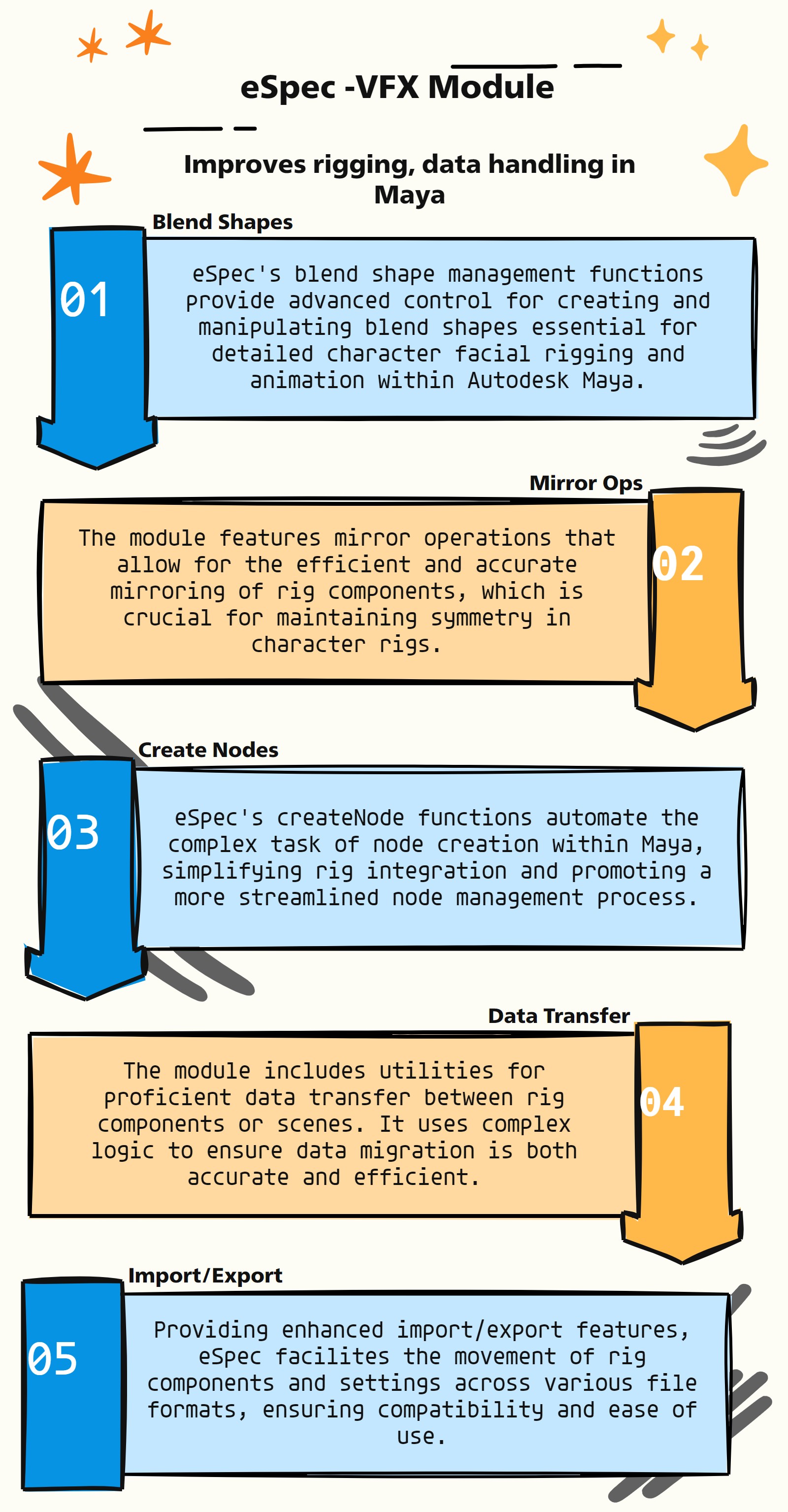
The eSpec module, adeptly crafted for VFX, specifically targets Autodesk Maya, delivering specific functions for rigging and enhancing the general Maya pipeline. Its capabilities focus on handling complex tasks like blend shapes, mirroring, node creation, data transfer, and import/export operations. Here’s an overview of its key features:
Blend Shape Management (bs_ Functions): eSpec provides advanced functionalities for managing blend shapes (bs_), crucial for facial rigging and detailed character animations, involving intricate logic to handle various blend shape scenarios.
Mirror Operations: The module includes sophisticated algorithms for mirroring rig components, a vital feature in creating symmetrical rigs efficiently and accurately.
CreateNode Functions (createNode_): It offers specialized functions for creating nodes within Maya, employing complex logic to streamline node management and integration within rigs.
Data Transfer Utilities: eSpec is equipped with tools for transferring data between different rig components or Maya scenes, handling complex logic to ensure accurate and efficient data migration.
Import/Export Features: The module simplifies the process of importing and exporting rig components or settings, accommodating complex algorithms to manage various file formats and compatibility issues.
Custom Algorithm Implementation: eSpec is designed with custom algorithms to handle specific rigging and pipeline tasks, enhancing the capability to deal with complex logic and scenarios unique to Maya.
Workflow Optimization: By automating and simplifying complex tasks within the Maya pipeline, eSpec significantly optimizes workflow, allowing for more efficient project execution and creative exploration.
Enhanced Rigging Tools: The module provides an array of enhanced rigging tools, each designed to tackle specific challenges in the rigging process, thus enabling more sophisticated and detailed rig setups.
- eSpec.__confirmAction(self, action)#
- Parameters:
action – To confirm the given action
- Returns:
True / False
- eSpec.__init__(self)#
To Support main auto rig scripts via eSpec
as_eSpecMain_v1.5
About
Author: (Subbaiah) Subbu Addanki
Character Supervisor (Rigging) & Programmer
Visit
http://www.pythonscripting.com
http://subbuadd.blogspot.com
Contact
Mail Id: subbu.add@gmail.com
Mobile No: +91-9741454400 / +91-9949005359
Copyright (c) as_eSpecMain
** (Subbaiah) Subbu Addanki. All Rights Reserved. **
- eSpec._isInTime(self, startDate=[2017, 1, 1], endDate=[2018, 1, 1], onlineTime=1, showDaysLeft=1, bufferTime=0)#
- eSpec._mayaVer(self)#
Purpose:
:: Retrieves the current version of Maya.
Retrieves the first four characters of the Maya version string.
Returns 2014 if the version string does not start with ‘20’.
- Parameters:
None – No parameters.
- Returns:
<int> #The year of the Maya version, e.g., 2018, 2022, etc.
- eSpec.addInfluences_skinClust(self, infList=None, skinMesh=None, useGeoInf=True, useProgress=1, skinWeight=0, **shArgs)#
[shArgs : il=infList, sm=skinMesh, ugi=useGeoInf, up=useProgress, sw=skinWeight]
Purpose:
:: Adds specified influences to a skin cluster on a given mesh.
This function is designed to enhance skin clusters by adding new influences.
It allows the addition of influences with options for geometry influence, progress tracking, and weight management.
Argument | Description ———|———— :param infList: <list, optional> #List of influences to be added. If None, selected objects are used.
infList =infList to be added to skinMesh
- Parameters:
skinMesh – <str, optional> #The mesh to which the influences are added. Last selected object is used if None. skinMesh = infList[-1], if skinMesh not given
useGeoInf – <bool, optional> #If True, uses geometry for influence. Defaults to True. useGeoInf = True | False (for ‘useGeometry’ arg)
useProgress – <int, optional> #Determines whether to display progress. Defaults to 1.
skinWeight – <float, optional> #Weight to assign to the new influences. Defaults to 0.
- Returns:
<None> #No return value, modifies the skin cluster directly.
Code Examples:
>>> addInfluences_skinClust(infList=['joint1', 'joint2'], skinMesh='mesh', useGeoInf=True, useProgress=1, skinWeight=0.5)
Args (from selection):
======================
If both Args are not given:
        infList =asN._selected()[0:-1]
        skinMesh =asN._selected()[-1]
- eSpec.applyCBS_cvShapeInv(self, skinMesh, correctivShp, driveAttr, exDriveAttr=None, cbsName=None, cbsIndex=None, goInitPos=True, *sdkLists, **shArgs)#
[shArgs : sm=skinMesh, cs=corShape, da=driveAttr, ed=exDriveAttr, cn=cbsName, ci=cbsIndex, gp=goInitPos]
Purpose:
:: Utilizes the cvShapeInverter plugin in Autodesk Maya to apply a corrective blendShape (CBS) to a skinned mesh. This is crucial for creating high-quality deformations, especially in character rigging for animation and visual effects.
Key for generating corrective shapes that counteract unwanted deformations during animation, resulting in more natural and realistic movement of skinned meshes.
- Parameters:
skinMesh – <str> #Name of the skin mesh to which the corrective blendShape will be applied.
corShape – <str> #Name of the corrective shape to be used.
driveAttr – <str> #Driver attribute for the set driven key (SDK) setup.
exDriveAttr – <str, optional> #External driver attribute for more complex SDK setups.
cbsName – <str, optional> #Name of the corrective blendShape node.
cbsIndex – <int, optional> #Index for the corrective blendShape target.
goInitPos – <bool> #Determines whether to return to initial pose after applying the CBS.
- Returns:
<str> #Name of the newly created corrective blendShape node or the existing one if cbsName is provided.
Code Examples:
>>> applyCBS_cvShapeInv('character_body', 'correctiveShape_bicepFlex', 'arm_ctrl.bicepFlex', exDriveAttr='arm_ctrl.fkIkSwitch', cbsName='bicepFlex_cbs', cbsIndex=0, goInitPos=True)
‘’’ This method needs plug-in : cvShapeInverter #_ adds a given corrective shape to skin mesh. #_ the jnts must be in pose to acheive the corrective shape.
example:
eSpec.applyCBS_cvShapeInv('skinMesh','corShape', 'psdName', driveAttr, *sdkLists)
*sdkList = [0, 5], [5, 1], [10, 0], [ and so on ], etc
Example Args:
skinMesh = 'body1'
correctivShp = 'body2'
exDriver ="left_wrist_fing_ctrl.fist"
driveAttr ="left_wrist_fing_ctrl.fist"
‘’’
graph TB Start[("fa:fa-play Start")] --> CheckSkinMeshIsSkinned{"/fas:fa-check-circle Check if Skin Mesh is Skinned"} CheckSkinMeshIsSkinned --> GenerateCorrectiveShapeName["/fas:fa-i-cursor Generate Corrective Shape Name"] GenerateCorrectiveShapeName --> ValidateDriveAttr["/fas:fa-search-plus Validate Drive Attribute"] ValidateDriveAttr --> CheckCBSExists{"/fas:fa-question-circle Check if CBS Exists"} CheckCBSExists --"If CBS Exists"--> SetCBSEnvelopeOff["/fas:fa-power-off Set CBS Envelope Off"] CheckCBSExists --"If CBS Does Not Exist"--> GetSetInitialPose["/fas:fa-play-circle Get/Set Initial Pose"] SetCBSEnvelopeOff --> GetSetInitialPose GetSetInitialPose --> CheckPluginLoaded{"/fas:fa-plug Check if Plugin Loaded"} CheckPluginLoaded --"If Plugin Not Loaded"--> LoadPlugin["/fas:fa-download Load cvShapeInverter Plugin"] LoadPlugin --> ApplyInverseShape["/fas:fa-magic Apply Inverse Shape"] CheckPluginLoaded --"If Plugin Loaded"--> ApplyInverseShape ApplyInverseShape --> RenameInverseShape["/fas:fa-tag Rename Inverse Shape"] RenameInverseShape --> ProcessBlendShapeTarget{"/fas:fa-object-group Process Blend Shape Target"} ProcessBlendShapeTarget --"If CBS Exists"--> AddTargetToCBS["/fas:fa-plus-square Add Target to CBS"] ProcessBlendShapeTarget --"If CBS Does Not Exist"--> CreateBlendShape["/fas:fa-plus-circle Create Blend Shape"] AddTargetToCBS --> CreateSDK["/fas:fa-key Create SDK"] CreateBlendShape --> CreateSDK CreateSDK --> SetInitialPose["/fas:fa-undo-alt Set Initial Pose"] SetInitialPose --> HideInverseShape["/fas:fa-eye-slash Hide Inverse Shape"] HideInverseShape --> ParentToCBSGroup["/fas:fa-sitemap Parent to CBS Group"] ParentToCBSGroup --> End[("fas:fa-stop End")] style Start fill:#00cc00,stroke:#000,stroke-width:3px style CheckSkinMeshIsSkinned fill:#ffcc00,stroke:#000,stroke-width:2px style GenerateCorrectiveShapeName fill:#ff9999,stroke:#000,stroke-width:2px style ValidateDriveAttr fill:#99ccff,stroke:#000,stroke-width:2px style CheckCBSExists fill:#cc99ff,stroke:#000,stroke-width:2px style SetCBSEnvelopeOff fill:#99ff99,stroke:#000,stroke-width:2px style GetSetInitialPose fill:#ffcc99,stroke:#000,stroke-width:2px style CheckPluginLoaded fill:#ccffcc,stroke:#000,stroke-width:2px style LoadPlugin fill:#ff9999,stroke:#000,stroke-width:2px style ApplyInverseShape fill:#99ccff,stroke:#000,stroke-width:2px style RenameInverseShape fill:#cc99ff,stroke:#000,stroke-width:2px style ProcessBlendShapeTarget fill:#99ff99,stroke:#000,stroke-width:2px style AddTargetToCBS fill:#ffcc99,stroke:#000,stroke-width:2px style CreateBlendShape fill:#ccffcc,stroke:#000,stroke-width:2px style CreateSDK fill:#ff9999,stroke:#000,stroke-width:2px style SetInitialPose fill:#99ccff,stroke:#000,stroke-width:2px style HideInverseShape fill:#cc99ff,stroke:#000,stroke-width:2px style ParentToCBSGroup fill:#99ff99,stroke:#000,stroke-width:2px style End fill:#ff6666,stroke:#000,stroke-width:3px- Flow Chart Description:
This flowchart illustrates the applyCBS_cvShapeInv function:
The method starts by checking if the skin mesh is already skinned.
It then generates a name for the corrective shape to be used.
The function validates the drive attribute to ensure it’s proper for the process.
It checks if a corrective blendShape (CBS) node already exists. If it does, the envelope of the CBS is set to off.
The method then gets or sets the initial pose based on the provided arguments.
It checks if the cvShapeInverter plugin is loaded. If not, it proceeds to load the plugin.
The method applies the inverse shape to the skin mesh using the cvShapeInverter tool.
After applying the inverse shape, it renames the inverse shape node.
The method processes the blend shape target, adding the target to an existing CBS node or creating a new blend shape node if necessary.
Set Driven Key (SDK) setups are created based on the provided sdkLists.
The initial pose of the mesh is then set again, reverting it to its original state.
The inverse shape node is hidden, and finally, it’s parented to a CBS group for organization.
The process ends after applying the corrective blendShape to the skin mesh.
- eSpec.applyCBS_getPoseReader(self, base=None, target=None, poseObj=None, coneAngle=90, getAngle=0, **shArgs)#
[shArgs : b=base, t=target, po=poseObj, ca=coneAngle, ga=getAngle]
Purpose:
:: Configures a pose reader for a control setup in Autodesk Maya. This function is typically used in rigging to create advanced control mechanisms.
A pose reader is used to determine the angle and position of a control object relative to a target, aiding in creating more dynamic and responsive rigging setups.
- Parameters:
base – <str> #The base object from which the pose is read.
target – <str> #The target object that the pose reader is analyzing.
poseObj – <str> #The object used to represent the pose.
coneAngle – <int> #The angle of the cone used in the pose reader setup.
getAngle – <bool> #Determines whether the function returns the angle between objects.
- Returns:
<str> #Returns the name of the pose reader node if getAngle is False, or the angle between base and target if getAngle is True.
Code Examples:
>>> applyCBS_getPoseReader('locator1', 'locator2', 'poseObj', 90, False)
graph TB Start[("fa:fa-play Start")] --> CheckSelections{"/fas:fa-check-circle Check Selections"} CheckSelections --> LoadMatrixPlugin{"/fas:fa-plug Load Matrix Plugin"} LoadMatrixPlugin --> CreatePoseLocAttrs["/fas:fa-plus-square Create Pose Loc Attributes"] CreatePoseLocAttrs --> CreateBaseMatrixNode["/fas:fa-code-branch Create Base Matrix Node"] CreateBaseMatrixNode --> CreatePoseMatrixNode["/fas:fa-code-branch Create Pose Matrix Node"] CreatePoseMatrixNode --> CreateTargetMatrixNode["/fas:fa-code-branch Create Target Matrix Node"] CreateTargetMatrixNode --> CreatePMAForTarget["/fas:fa-plus-square Create PMA For Target"] CreatePMAForTarget --> CreatePMAForPose["/fas:fa-plus-square Create PMA For Pose"] CreatePMAForPose --> CreateAngleBetweenNode["/fas:fa-angle-double-up Create Angle Between Node"] CreateAngleBetweenNode --> CreateOutputPMA["/fas:fa-plus-square Create Output PMA"] CreateOutputPMA --> CheckGetAngle{"/fas:fa-question Check Get Angle"} CheckGetAngle --"If False"--> CreateMDNode["/fas:fa-times Create MD Node"] CreateMDNode --> CreateConditionNode["/fas:fa-code-branch Create Condition Node"] CreateConditionNode --> CreateFinalOutputPMA["/fas:fa-plus-square Create Final Output PMA"] CreateFinalOutputPMA --> End[("fas:fa-stop End")] CheckGetAngle --"If True"--> ReturnAngleBetweenNode["/fas:fa-arrow-right Return Angle Between Node"] ReturnAngleBetweenNode --> End style Start fill:#00cc00,stroke:#000,stroke-width:3px style CheckSelections fill:#ffcc00,stroke:#000,stroke-width:2px style LoadMatrixPlugin fill:#ff9999,stroke:#000,stroke-width:2px style CreatePoseLocAttrs fill:#99ccff,stroke:#000,stroke-width:2px style CreateBaseMatrixNode fill:#cc99ff,stroke:#000,stroke-width:2px style CreatePoseMatrixNode fill:#99ff99,stroke:#000,stroke-width:2px style CreateTargetMatrixNode fill:#ffcc99,stroke:#000,stroke-width:2px style CreatePMAForTarget fill:#ccffcc,stroke:#000,stroke-width:2px style CreatePMAForPose fill:#ff9999,stroke:#000,stroke-width:2px style CreateAngleBetweenNode fill:#99ccff,stroke:#000,stroke-width:2px style CreateOutputPMA fill:#cc99ff,stroke:#000,stroke-width:2px style CheckGetAngle fill:#99ff99,stroke:#000,stroke-width:2px style CreateMDNode fill:#ffcc99,stroke:#000,stroke-width:2px style CreateConditionNode fill:#ccffcc,stroke:#000,stroke-width:2px style CreateFinalOutputPMA fill:#ff9999,stroke:#000,stroke-width:2px style ReturnAngleBetweenNode fill:#99ccff,stroke:#000,stroke-width:2px style End fill:#ff6666,stroke:#000,stroke-width:3px- Flow Chart Description:
This flowchart illustrates the applyCBS_getPoseReader function:
The process starts by checking if the base, target, and pose object selections are provided. If not, it uses selected objects from the scene.
It ensures that the Matrix Plugin is loaded for the necessary matrix operations.
The method then creates attributes on the pose locator and pose object for storing pose information.
It creates a matrix node for the base object to gather its world matrix data.
Similarly, matrix nodes for the pose and target objects are created to gather their world matrix data.
Point Matrix Add (PMA) nodes are created for the target and pose, calculating the difference between their positions and the base.
An Angle Between node is created to determine the angle between the target and pose vectors.
An Output PMA node is then created to output the calculated angle.
The method checks if the angle value is required. If not, it proceeds to create a Multiply Divide (MD) node and a Condition node for further processing.
A final Output PMA node is created to provide the pose value based on the condition.
If the angle value is required, the method returns the angle between the base and target objects.
The process ends after either returning the pose value or the angle value.
- eSpec.applyCBS_poseDeformer(self, skinMesh, correctivShp, poseSpaceJnt, psdName, exDriver=None, driveAttr=None, *sdkLists, **shArgs)#
[shArgs : sm=skinMesh, csh=correctivShp, psj=poseSpaceJnt, pn=psdName, ed=exDriver, da=driveAttr, sl=sdkLists]
Purpose:
:: Sets up a pose deformer for a given skin mesh in Autodesk Maya. This function is commonly used in rigging to create corrective shapes that are activated based on joint positions.
This process is essential for achieving realistic deformations in character rigs, particularly in areas like facial expressions or muscle flexing.
- Parameters:
skinMesh – <str> #The name of the skinned geometry to which the pose deformer is applied.
correctivShp – <str> #The name of the corrective shape that will be driven by the pose deformer.
poseSpaceJnt – <str> #The joint that influences the pose deformer.
psdName – <str> #The name of the pose deformer node.
exDriver – <str> #An external driver attribute (optional) that can drive the pose deformer.
driveAttr – <str> #The attribute on the poseSpaceJnt that drives the pose deformer.
sdkLists – <list> #A list of set driven key (SDK) values to define the behavior of the pose deformer.
- Returns:
None #This function does not return a value but configures the pose deformer on the specified mesh.
Code Examples:
>>> applyCBS_poseDeformer('character_geo', 'biceps_corShape_geo', 'elbow_jnt', 'L_Hands_PSD', None, None, [[0, 5], [5, 1], [10, 0]])
‘’’ This method needs plug-in : poseDeformer #_ adds a given corrective shape to skin mesh. #_ the jnts must be in pose to acheive the corrective shape.
example:
eSpec.apply_poseDeform('character_geo','biceps_corShape_geo', 'elbow_jnt', psdName, exDriver, driveAttr, *sdkLists)
*sdkList = [0, 5], [5, 1], [10, 0], [ and so on ], etc
Example Args:
skinMesh = 'ubaidaArmor_R_glove_hiRes_geo'
correctivShp = 'Rt_fist_glove_5'
poseSpaceJnt = 'L_Elbow_jnt' | ['L_Elbow_Jnt', 'parent_jnt']
psdName = 'L_Hands_PSD'
exDriver ="left_wrist_fing_ctrl.fist"
driveAttr =None, 'tx' or "left_wrist_fing_ctrl.fist"
‘’’
graph TB Start[("fa:fa-play Start")] --> CheckPlugin{{"/fas:fa-question-circle Check Plugin"}} CheckPlugin --"Plugin poseDeformer & poseReader loaded"--> ValidateInputs["/fas:fa-check-square Validate Inputs"] CheckPlugin --"Plugin poseDeformer & poseReader not loaded"--> RaiseError1[("fas:fa-exclamation-triangle Raise Error")] ValidateInputs --> CheckSkinMesh{{"/fas:fa-search Check if Skin Mesh"}} CheckSkinMesh --"Is Skin Mesh"--> CheckPoseSpaceJnt{{"/fas:fa-search Check Pose Space Joint"}} CheckSkinMesh --"Not Skin Mesh"--> RaiseError2[("fas:fa-exclamation-triangle Raise Error")] CheckPoseSpaceJnt --> CheckExDriver{{"/fas:fa-search Check ExDriver"}} CheckExDriver --"ExDriver Exists & Valid"--> CheckDriveAttr{{"/fas:fa-search Check Drive Attribute"}} CheckExDriver --"ExDriver Invalid or Not Exists"--> RaiseError3[("fas:fa-exclamation-triangle Raise Error")] CheckDriveAttr --> SetInitialPose["/fas:fa-play-circle Set Initial Pose"] SetInitialPose --> LoadUI["/fas:fa-desktop Load UI"] LoadUI --> DefineSkinMesh["/fas:fa-object-ungroup Define Skin Mesh"] DefineSkinMesh --> CheckPoseDeformer{{"/fas:fa-question-circle Check Pose Deformer"}} CheckPoseDeformer --"Pose Deformer Exists"--> PrepareSculpting["/fas:fa-paint-brush Prepare Sculpting"] CheckPoseDeformer --"New Pose Deformer Required"--> CreatePoseDeformer["/fas:fa-plus-circle Create Pose Deformer"] PrepareSculpting --> EnterPoseSpaceJntUI["/fas:fa-keyboard Enter Pose Space Joint in UI"] EnterPoseSpaceJntUI --> EnterParentJntUI["/fas:fa-keyboard Enter Parent Joint in UI"] EnterParentJntUI --> EnterPoseNameUI["/fas:fa-keyboard Enter Pose Name in UI"] EnterPoseNameUI --> CreatePoseDeformer2["/fas:fa-plus-circle Create Pose Deformer"] CreatePoseDeformer2 --> CreateSDKs{{"/fas:fa-cogs Create SDKs"}} CreateSDKs --"ExDriver Exists"--> SetDrivenKeys["/fas:fa-key Set Driven Keys"] CreateSDKs --"ExDriver Not Exists"--> SetInitialPoseAgain["/fas:fa-undo-alt Set Initial Pose Again"] SetDrivenKeys --> SetInitialPoseAgain SetInitialPoseAgain --> End[("fas:fa-stop End")] style Start fill:#00cc00,stroke:#000,stroke-width:3px style CheckPlugin fill:#ffcc00,stroke:#000,stroke-width:2px style ValidateInputs fill:#ff9999,stroke:#000,stroke-width:2px style CheckSkinMesh fill:#99ccff,stroke:#000,stroke-width:2px style CheckPoseSpaceJnt fill:#cc99ff,stroke:#000,stroke-width:2px style CheckExDriver fill:#99ff99,stroke:#000,stroke-width:2px style CheckDriveAttr fill:#ffcc00,stroke:#000,stroke-width:2px style SetInitialPose fill:#ff9999,stroke:#000,stroke-width:2px style LoadUI fill:#99ccff,stroke:#000,stroke-width:2px style DefineSkinMesh fill:#cc99ff,stroke:#000,stroke-width:2px style CheckPoseDeformer fill:#99ff99,stroke:#000,stroke-width:2px style PrepareSculpting fill:#ffcc00,stroke:#000,stroke-width:2px style EnterPoseSpaceJntUI fill:#ff9999,stroke:#000,stroke-width:2px style EnterParentJntUI fill:#99ccff,stroke:#000,stroke-width:2px style EnterPoseNameUI fill:#cc99ff,stroke:#000,stroke-width:2px style CreatePoseDeformer2 fill:#99ff99,stroke:#000,stroke-width:2px style CreateSDKs fill:#ffcc00,stroke:#000,stroke-width:2px style SetDrivenKeys fill:#ff9999,stroke:#000,stroke-width:2px style SetInitialPoseAgain fill:#99ccff,stroke:#000,stroke-width:2px style End fill:#ff6666,stroke:#000,stroke-width:3px style RaiseError1 fill:#ff6666,stroke:#000,stroke-width:3px style RaiseError2 fill:#ff6666,stroke:#000,stroke-width:3px style RaiseError3 fill:#ff6666,stroke:#000,stroke-width:3px- Flow Chart Description:
This flowchart illustrates the applyCBS_poseDeformer function:
The process starts by checking if the required plugins are loaded. If not, it raises an error.
Next, it validates the inputs: skinMesh, correctivShp, poseSpaceJnt, psdName, exDriver, driveAttr, and sdkLists.
The function checks if the skinMesh is a skinned mesh and if the poseSpaceJnt is a skinned joint.
If an external driver is provided, it checks for its existence and validity.
The initial pose is set based on the exDriver or the joint driver.
The UI for poseDeformer is then loaded, and the skinMesh is defined.
The function checks if a new poseDeformer is needed or if an existing one can be used.
It prepares for sculpting the corrective shape by entering poseSpaceJnt, parentJnt, and the pose name in the UI.
Finally, the poseDeformer is created, and Set Driven Keys are set up if an external driver is provided.
- eSpec.applyColors(self, applyType='series', **shArgs)#
[shArgs : at=applyType]
Purpose:
:: Assigns colors to mesh objects in Autodesk Maya based on a predefined color scheme. The function can apply colors in a series or randomly, enhancing the visualization of different mesh components during the rigging or modeling process.
Useful for quickly differentiating various parts of a model or rig, especially in complex scenes or during early development stages.
- Parameters:
applyType – <str> #Determines the pattern of color application. Options are ‘series’ for sequential color assignment, or ‘random’ for random color distribution among the mesh objects.
- Returns:
None #Applies colors to the selected or specified mesh objects but does not return any value.
Code Examples:
>>> applyColors(applyType='series')
Args: applyType = ‘series’ | ‘random’
Usage:
Works on selected mesh or all meshes in the scene
If no geometry is selected, Selects all geometry in the scene.
If selection is not geometry, It escapes and moves to next.
graph TB Start[("fa:fa-play Start")] --> CheckShArgs{{"/fas:fa-question Check for shArgs"}} CheckShArgs --"If shArgs is provided" --> UpdateApplyType["/fas:fa-sync-alt Update applyType"] UpdateApplyType --> CheckSelected["/fas:fa-check-square Check if something is selected"] CheckShArgs --"If shArgs is not provided" --> CheckSelected CheckSelected --"If nothing is selected" --> SelectMeshes["/fas:fa-object-group Select all meshes"] SelectMeshes --> GetGeoList1["/fas:fa-list Get geoList from selected meshes"] CheckSelected --"If something is selected" --> GetGeoList2["/fas:fa-list Get geoList from selection"] GetGeoList1 --> InitializeColorDict["/fas:fa-palette Initialize colDict and colNames"] GetGeoList2 --> InitializeColorDict InitializeColorDict --> ForEachGeo["/fas:fa-repeat For each geo in geoList"] ForEachGeo --"For each geometry" --> CheckMesh["/fas:fa-check Check if geo is mesh"] CheckMesh --"If geo is not a mesh" --> WarningGeo["/fas:fa-exclamation-triangle Display warning"] WarningGeo --> ContinueLoop[("/fas:fa-arrow-right Continue loop")] CheckMesh --"If geo is a mesh" --> ApplyShaderDecision{"/fas:fa-code-branch Apply Shader Decision"} ApplyShaderDecision --"Special conditions met" --> ApplySpecialShader["/fas:fa-magic Apply special shader"] ApplyShaderDecision --"Standard conditions" --> ApplyStandardShader["/fas:fa-paint-brush Apply standard shader"] ApplySpecialShader --> IncrementColorIndex["/fas:fa-plus Increment colIndx"] ApplyStandardShader --> IncrementColorIndex IncrementColorIndex --"Continue to next geo" --> ForEachGeo ForEachGeo --"End of geoList" --> End[("fas:fa-stop End")] style Start fill:#00cc00,stroke:#000,stroke-width:3px style CheckShArgs fill:#ffcc00,stroke:#000,stroke-width:2px style UpdateApplyType fill:#ff9999,stroke:#000,stroke-width:2px style CheckSelected fill:#99ccff,stroke:#000,stroke-width:2px style SelectMeshes fill:#cc99ff,stroke:#000,stroke-width:2px style GetGeoList1 fill:#99ff99,stroke:#000,stroke-width:2px style GetGeoList2 fill:#99ff99,stroke:#000,stroke-width:2px style InitializeColorDict fill:#ff9999,stroke:#000,stroke-width:2px style ForEachGeo fill:#ffcc00,stroke:#000,stroke-width:2px style CheckMesh fill:#99ccff,stroke:#000,stroke-width:2px style WarningGeo fill:#ff6666,stroke:#000,stroke-width:2px style ContinueLoop fill:#99ff99,stroke:#000,stroke-width:2px style ApplyShaderDecision fill:#cc99ff,stroke:#000,stroke-width:2px style ApplySpecialShader fill:#ff9999,stroke:#000,stroke-width:2px style ApplyStandardShader fill:#99ccff,stroke:#000,stroke-width:2px style IncrementColorIndex fill:#cc99ff,stroke:#000,stroke-width:2px style End fill:#ff6666,stroke:#000,stroke-width:3px- Flow Chart Description:
This flowchart illustrates the applyColors function:
The process starts by checking if shArgs are provided and updates applyType if necessary.
It checks if any geometry is selected. If not, it selects all mesh types in the scene.
The selected geometries are stored in geoList.
A dictionary of color names and values (colDict) and a sorted list of color names (colNames) are initialized.
For each geometry in geoList, the function checks if it is a mesh.
If the geometry is not a mesh, a warning is displayed, and the loop continues.
If it is a mesh, the function decides whether to apply a standard or special shader based on specific conditions.
The color index is incremented after applying the shader to each geometry.
- eSpec.applyDeform_Squash(self, trgtObj, rotList=None, snapToTrgt=True, squashName=None, **kwargs)#
[shArgs : tl=trgtList, rl=rotList, st=snapToTrgt, sn=squashName]
Purpose:
:: Applies a squash deformer to the specified target object or objects, with optional rotation and snapping controls.
This function creates a squash deformer for a given target object or a list of objects.
The deformer’s rotation can be set, and it can optionally be snapped to a target position.
- Parameters:
trgtObj – <str/list> #Target object or list of objects to apply the squash deformer to.
rotList – <list, optional> #List specifying the rotation of the deformer in degrees. Default is [0, 0, 0].
snapToTrgt – <bool> #Whether to snap the deformer to a target position. Default is True.
squashName – <str, optional> #Name for the created squash deformer. If not specified, a default name is generated.
- Returns:
<list> #Returns a list of tuples, each containing a handle and node for the created squash deformer.
Code Examples:
>>> applyDeform_Squash('pCube1', rotList=[45, 0, 0], snapToTrgt=True, squashName='mySquash')
'''
Args:
snapToTrgt                      = obj | list[0, 0, 0]
rotList                         = list[0, 0, 0]
Available kwargs        = {'lowBound' :0, 'highBound' :2}
Available Attrs         = {'lowBound' :0, 'highBound' :2, 'startSmoothness' :0, 'endSmoothness' :0, 'factor' :0, 'maxExpandPos' :0.5}
default kwargs          = {'lowBound' :0, 'highBound' :2, 'autoParent':True}
Returns:
if len(trgtObjList) == 1:
        return squashList[0]    #_ [asNode(squashHand), PyNode(squashNode)]
else:
        return squashList               #_ [[squashHand1, squashNode1], [squashHand2, squashNode2], ..]
‘’’
graph TB Start[("fa:fa-play Start")] --> CheckShArgs{{"/fas:fa-question Check for shArgs"}} CheckShArgs --"If shArgs is provided" --> UpdateTrgtObj["/fas:fa-sync-alt Update trgtObj"] UpdateTrgtObj --> UpdateRotList["/fas:fa-sync-alt Update rotList"] UpdateRotList --> UpdateSnapToTrgt["/fas:fa-sync-alt Update snapToTrgt"] UpdateSnapToTrgt --> UpdateSquashName["/fas:fa-sync-alt Update squashName"] UpdateSquashName --> SetDefaultKwargs["/fas:fa-cogs Set Default kwargs"] CheckShArgs --"If shArgs is not provided" --> SetDefaultKwargs SetDefaultKwargs --> InitializeTrgtList["/fas:fa-list-alt Initialize trgtList"] InitializeTrgtList --> ForEachTrgtObj["/fas:fa-repeat For each trgtObj in trgtList"] ForEachTrgtObj --"For each target object" --> SelectTrgtObj["/fas:fa-mouse-pointer Select trgtObj"] SelectTrgtObj --> CreateSquashDeformer["/fas:fa-compress-arrows-alt Create squash deformer"] CreateSquashDeformer --> RenameSquash["/fas:fa-i-cursor Rename squash deformer"] RenameSquash --> CheckRotList["/fas:fa-check-circle Check if rotList is provided"] CheckRotList --"If rotList is provided" --> SetRotation["/fas:fa-sync-alt Set Rotation"] SetRotation --> CheckSnapToTrgt["/fas:fa-check-circle Check if snapToTrgt is True"] CheckRotList --"If rotList is not provided" --> CheckSnapToTrgt CheckSnapToTrgt --"If snapToTrgt is True" --> SnapPosition["/fas:fa-map-pin Snap Position"] SnapPosition --> AppendSquashList["/fas:fa-list-ol Append to squashList"] CheckSnapToTrgt --"If snapToTrgt is False" --> AppendSquashList AppendSquashList --> IncrementCounter["/fas:fa-plus Increment counter"] IncrementCounter --"Continue to next target object" --> ForEachTrgtObj ForEachTrgtObj --"End of trgtList" --> ReturnDecision{"/fas:fa-code-branch Return Decision"} ReturnDecision --"If single target object" --> ReturnSingle["/fas:fa-arrow-right Return single squash deformer"] ReturnDecision --"If multiple target objects" --> ReturnMultiple["/fas:fa-arrow-right Return multiple squash deformers"] ReturnSingle --> End[("fas:fa-stop End")] ReturnMultiple --> End style Start fill:#00cc00,stroke:#000,stroke-width:3px style CheckShArgs fill:#ffcc00,stroke:#000,stroke-width:2px style UpdateTrgtObj fill:#ff9999,stroke:#000,stroke-width:2px style UpdateRotList fill:#ff9999,stroke:#000,stroke-width:2px style UpdateSnapToTrgt fill:#ff9999,stroke:#000,stroke-width:2px style UpdateSquashName fill:#ff9999,stroke:#000,stroke-width:2px style SetDefaultKwargs fill:#99ccff,stroke:#000,stroke-width:2px style InitializeTrgtList fill:#cc99ff,stroke:#000,stroke-width:2px style ForEachTrgtObj fill:#ffcc00,stroke:#000,stroke-width:2px style SelectTrgtObj fill:#99ff99,stroke:#000,stroke-width:2px style CreateSquashDeformer fill:#99ccff,stroke:#000,stroke-width:2px style RenameSquash fill:#cc99ff,stroke:#000,stroke-width:2px style CheckRotList fill:#ff6666,stroke:#000,stroke-width:2px style SetRotation fill:#99ff99,stroke:#000,stroke-width:2px style CheckSnapToTrgt fill:#cc99ff,stroke:#000,stroke-width:2px style SnapPosition fill:#ff9999,stroke:#000,stroke-width:2px style AppendSquashList fill:#99ccff,stroke:#000,stroke-width:2px style IncrementCounter fill:#cc99ff,stroke:#000,stroke-width:2px style ReturnDecision fill:#ff6666,stroke:#000,stroke-width:2px style ReturnSingle fill:#99ff99,stroke:#000,stroke-width:2px style ReturnMultiple fill:#99ccff,stroke:#000,stroke-width:2px style End fill:#ff6666,stroke:#000,stroke-width:3px- Flow Chart Description:
This flowchart illustrates the applyDeform_Squash function:
The function begins by checking if shArgs are provided, and updates trgtObj, rotList, snapToTrgt, and squashName accordingly.
If no kwargs are provided, default values are set.
It initializes trgtList based on the trgtObj type.
For each target object in trgtList, the function selects the target, creates a squash deformer, and renames it based on conditions.
The rotation is set if rotList is provided.
The position of the squash deformer is snapped if snapToTrgt is True.
The function appends each created squash deformer to squashList.
Finally, it returns a single squash deformer or a list of deformers based on the number of target objects.
- eSpec.applyDeformers(self, trgtList=None, deformTypes=['bend'], initRot=[0, 0, 0], snapToTrgt=0, suffixName=None, animCtrl=None, **shArgs)#
[shArgs: ]
Purpose:
:: Applies specified deformers to a target list of objects with additional options for initialization and snapping.
This function is versatile in applying various deformation effects such as bending, flaring, etc.
Provides granular control over the deformation process with parameters for initial rotation, snapping, and grouping.
- Parameters:
trgtList – <list, optional> #List of target objects to apply deformers. Defaults to currently selected objects.
deformTypes – <list> #Types of deformers to apply (e.g., [‘bend’, ‘twist’]).
initRot – <list> #Initial rotation to be applied in the format [x, y, z].
snapToTrgt – <int> #Determines if the deformer should snap to a target position. 0 for no snap, 1 for snapping.
suffixName – <str, optional> #Suffix to append to the deformer names.
animCtrl – <str, optional> #Animation control to connect with the deformer.
shArgs – <dict, optional> #Short arguments for convenience and script compatibility.
- Returns:
<list> #A list of applied deformers and their corresponding nodes.
Code Examples:
>>> applyDeformers(objList, deformTypes=['bend', 'twist'], initRot=[0, 0, 0], snapToTrgt=1)
Args:
snapToTrgt                      = obj | list[0, 0, 0]
initRot                         = list[0, 0, 0]
Available Attrs         = {'lowBound' :0, 'highBound' :2, 'startSmoothness' :0, 'endSmoothness' :0, 'factor' :0, 'maxExpandPos' :0.5}
default shArgs          = {'lowBound' :0, 'highBound' :2, 'autoParent':True}
deformTypes = 'bend' | 'flare' | 'sine' | 'squash' | 'twist' | 'wave'
Returns:
if len(trgtListList) == 1:
        return squashList[0]    #_ [asNode(squashHand), PyNode(squashNode)]
else:
        return squashList               #_ [[squashHand1, squashNode1], [squashHand2, squashNode2], ..]
graph TB Start[("fa:fa-play Start")] --> CheckShArgs{{"/fas:fa-question Check for shArgs"}} CheckShArgs --"If shArgs is provided" --> UpdateTrgtObj["/fas:fa-sync-alt Update trgtObj"] UpdateTrgtObj --> UpdateRotList["/fas:fa-sync-alt Update rotList"] UpdateRotList --> UpdateSnapToTrgt["/fas:fa-sync-alt Update snapToTrgt"] UpdateSnapToTrgt --> UpdateSquashName["/fas:fa-sync-alt Update squashName"] UpdateSquashName --> SetDefaultKwargs["/fas:fa-cogs Set Default kwargs"] CheckShArgs --"If shArgs is not provided" --> SetDefaultKwargs SetDefaultKwargs --> InitializeTrgtList["/fas:fa-list-alt Initialize trgtList"] InitializeTrgtList --> ForEachTrgtObj["/fas:fa-repeat For each trgtObj in trgtList"] ForEachTrgtObj --"For each target object" --> SelectTrgtObj["/fas:fa-mouse-pointer Select trgtObj"] SelectTrgtObj --> CreateSquashDeformer["/fas:fa-compress-arrows-alt Create squash deformer"] CreateSquashDeformer --> RenameSquash["/fas:fa-i-cursor Rename squash deformer"] RenameSquash --> CheckRotList["/fas:fa-check-circle Check if rotList is provided"] CheckRotList --"If rotList is provided" --> SetRotation["/fas:fa-sync-alt Set Rotation"] SetRotation --> CheckSnapToTrgt["/fas:fa-check-circle Check if snapToTrgt is True"] CheckRotList --"If rotList is not provided" --> CheckSnapToTrgt CheckSnapToTrgt --"If snapToTrgt is True" --> SnapPosition["/fas:fa-map-pin Snap Position"] SnapPosition --> AppendSquashList["/fas:fa-list-ol Append to squashList"] CheckSnapToTrgt --"If snapToTrgt is False" --> AppendSquashList AppendSquashList --> IncrementCounter["/fas:fa-plus Increment counter"] IncrementCounter --"Continue to next target object" --> ForEachTrgtObj ForEachTrgtObj --"End of trgtList" --> ReturnDecision{"/fas:fa-code-branch Return Decision"} ReturnDecision --"If single target object" --> ReturnSingle["/fas:fa-arrow-right Return single squash deformer"] ReturnDecision --"If multiple target objects" --> ReturnMultiple["/fas:fa-arrow-right Return multiple squash deformers"] ReturnSingle --> End[("fas:fa-stop End")] ReturnMultiple --> End style Start fill:#00cc00,stroke:#000,stroke-width:3px style CheckShArgs fill:#ffcc00,stroke:#000,stroke-width:2px style UpdateTrgtObj fill:#ff9999,stroke:#000,stroke-width:2px style UpdateRotList fill:#ff9999,stroke:#000,stroke-width:2px style UpdateSnapToTrgt fill:#ff9999,stroke:#000,stroke-width:2px style UpdateSquashName fill:#ff9999,stroke:#000,stroke-width:2px style SetDefaultKwargs fill:#99ccff,stroke:#000,stroke-width:2px style InitializeTrgtList fill:#cc99ff,stroke:#000,stroke-width:2px style ForEachTrgtObj fill:#ffcc00,stroke:#000,stroke-width:2px style SelectTrgtObj fill:#99ff99,stroke:#000,stroke-width:2px style CreateSquashDeformer fill:#99ccff,stroke:#000,stroke-width:2px style RenameSquash fill:#cc99ff,stroke:#000,stroke-width:2px style CheckRotList fill:#ff6666,stroke:#000,stroke-width:2px style SetRotation fill:#99ff99,stroke:#000,stroke-width:2px style CheckSnapToTrgt fill:#cc99ff,stroke:#000,stroke-width:2px style SnapPosition fill:#ff9999,stroke:#000,stroke-width:2px style AppendSquashList fill:#99ccff,stroke:#000,stroke-width:2px style IncrementCounter fill:#cc99ff,stroke:#000,stroke-width:2px style ReturnDecision fill:#ff6666,stroke:#000,stroke-width:2px style ReturnSingle fill:#99ff99,stroke:#000,stroke-width:2px style ReturnMultiple fill:#99ccff,stroke:#000,stroke-width:2px style End fill:#ff6666,stroke:#000,stroke-width:3px- Flow Chart Description:
This flowchart illustrates the applyDeform_Squash function:
The function begins by checking if shArgs are provided, and updates trgtObj, rotList, snapToTrgt, and squashName accordingly.
If no kwargs are provided, default values are set.
It initializes trgtList based on the trgtObj type.
For each target object in trgtList, the function selects the target, creates a squash deformer, and renames it based on conditions.
The rotation is set if rotList is provided.
The position of the squash deformer is snapped if snapToTrgt is True.
The function appends each created squash deformer to squashList.
Finally, it returns a single squash deformer or a list of deformers based on the number of target objects.
- eSpec.applyShader(self, meshList, shaderNode='aiStandard', colorVal=[1, 0, 0], shaderName=None, **shArgs)#
[shArgs : ml=meshList, sn=shaderNode, cv=colorVal, sn=shaderName]
Purpose:
:: Applies a specified shader with a given color value to a list of meshes in Autodesk Maya. This function is particularly useful for quickly applying uniform or dummy colors to multiple mesh objects, typically used in the early stages of rigging before detailed texturing.
Facilitates rapid visualization of rigging and modeling work, providing a uniform color scheme for easier identification and assessment of mesh objects.
- Parameters:
meshList – <list> #List of mesh objects to which the shader will be applied.
shaderNode – <str> #Type of shader node to create and apply (e.g., ‘aiStandard’).
colorVal – <list> #RGB color value to be applied to the shader (e.g., [1, 0, 0] for red).
shaderName – <str, optional> #Optional custom name for the created shader node.
- Returns:
<str> #Name of the newly created or existing shader node applied to the meshes.
Code Examples:
>>> applyShader(['cube1', 'sphere1'], 'aiStandard', [0.5, 0.5, 1], 'blueShader')
graph TB Start[("fa:fa-play Start")] --> CheckShArgs{{"/fas:fa-question Check for shArgs"}} CheckShArgs --"If shArgs are provided" --> UpdateMeshList["/fas:fa-sync-alt Update meshList"] UpdateMeshList --> UpdateShaderNode["/fas:fa-sync-alt Update shaderNode"] UpdateShaderNode --> UpdateColorVal["/fas:fa-palette Update colorVal"] UpdateColorVal --> UpdateShaderName["/fas:fa-i-cursor Update shaderName"] CheckShArgs --"If shArgs are not provided" --> InitializeMeshList["/fas:fa-list-alt Initialize meshList"] UpdateShaderName --> InitializeMeshList InitializeMeshList --> SetDefaultShaderName["/fas:fa-tag Set Default Shader Name"] SetDefaultShaderName --> CheckShaderExists{{"/fas:fa-search Check if Shader Exists"}} CheckShaderExists --"If shader does not exist" --> CreateShader["/fas:fa-plus-circle Create Shader"] CreateShader --> SetColor["/fas:fa-tint Set Shader Color"] CheckShaderExists --"If shader exists" --> SelectMeshList["/fas:fa-mouse-pointer Select Mesh List"] SetColor --> SelectMeshList SelectMeshList --> AssignShader["/fas:fa-brush Assign Shader"] AssignShader --> ReturnShaderName["/fas:fa-arrow-right Return Shader Name"] ReturnShaderName --> End[("fas:fa-stop End")] style Start fill:#00cc00,stroke:#000,stroke-width:3px style CheckShArgs fill:#ffcc00,stroke:#000,stroke-width:2px style UpdateMeshList fill:#ff9999,stroke:#000,stroke-width:2px style UpdateShaderNode fill:#ff9999,stroke:#000,stroke-width:2px style UpdateColorVal fill:#ff9999,stroke:#000,stroke-width:2px style UpdateShaderName fill:#ff9999,stroke:#000,stroke-width:2px style InitializeMeshList fill:#99ccff,stroke:#000,stroke-width:2px style SetDefaultShaderName fill:#cc99ff,stroke:#000,stroke-width:2px style CheckShaderExists fill:#ff6666,stroke:#000,stroke-width:2px style CreateShader fill:#99ff99,stroke:#000,stroke-width:2px style SetColor fill:#99ccff,stroke:#000,stroke-width:2px style SelectMeshList fill:#cc99ff,stroke:#000,stroke-width:2px style AssignShader fill:#ff9999,stroke:#000,stroke-width:2px style ReturnShaderName fill:#99ccff,stroke:#000,stroke-width:2px style End fill:#ff6666,stroke:#000,stroke-width:3px- Flow Chart Description:
This flowchart illustrates the applyShader function:
The function begins by checking and updating parameters like meshList, shaderNode, colorVal, and shaderName from shArgs if provided.
If meshList is not a list, it is converted to a list.
A default shader name is set if shaderName is not provided.
The function checks if the shader already exists in the scene.
If the shader does not exist, it is created and its color is set based on colorVal.
The shader is then assigned to all meshes in meshList.
Finally, the name of the shader is returned.
- eSpec.apply_B4Publish(self, **shArgs)#
Purpose:
:: Prepares the scene for publishing by applying a series of predefined settings and cleanup operations.
Ideal for finalizing scenes before delivery, ensuring consistency and adherence to production standards.
Automates tasks like visibility settings, rig adjustments, and cleanup of unnecessary elements.
Argument | Description ———|———— :no additional parameters: #This function operates without specific input arguments.
- Returns:
<None> #No return value. Modifies the scene based on predefined publishing criteria.
Code Examples:
>>> apply_B4Publish()
Features:#
1. all settings related to ‘Placer’2. Closing unwanted windows (some times it doesn’t work or closes complete Maya. Need to find better solution). So save your file before running this script.3. Putting the scene contents to bounding box..4. Putting hands rig in to IK mode & making all hand controllers to Zero both in IK & FK modes5. deletes ‘bindPose’6. deletes ‘nameSpace:’ (new update from Shimjith)7. deletes unwanted expressions like ‘cycleOff’ (new update)graph TB Start[("fa:fa-play Start")] --> LoopRemoveNS{{"/fas:fa-sync-alt Loop Remove Namespace"}} LoopRemoveNS --"For 3 iterations"--> CallRemoveNS["/fas:fa-times Remove Namespaces"] CallRemoveNS --> EndLoopRemoveNS[("fas:fa-repeat End Loop Remove Namespace")] EndLoopRemoveNS --"End of loop"--> SetVisibilitySettings["/fas:fa-eye-slash Set Visibility Settings"] SetVisibilitySettings --> SetIKModeSettings["/fas:fa-hand-rock Set IK Mode Settings"] SetIKModeSettings --> DeleteUnwantedItems["/fas:fa-trash-alt Delete Unwanted Items"] DeleteUnwantedItems --> CallSwitchOffJiggle["/fas:fa-toggle-off Switch Off Jiggle"] CallSwitchOffJiggle --> End[("fas:fa-stop End")] style Start fill:#00cc00,stroke:#000,stroke-width:3px style LoopRemoveNS fill:#ffcc00,stroke:#000,stroke-width:2px style CallRemoveNS fill:#ff9999,stroke:#000,stroke-width:2px style EndLoopRemoveNS fill:#99ccff,stroke:#000,stroke-width:2px style SetVisibilitySettings fill:#cc99ff,stroke:#000,stroke-width:2px style SetIKModeSettings fill:#99ff99,stroke:#000,stroke-width:2px style DeleteUnwantedItems fill:#ffcc99,stroke:#000,stroke-width:2px style CallSwitchOffJiggle fill:#ccffcc,stroke:#000,stroke-width:2px style End fill:#ff6666,stroke:#000,stroke-width:3px- Flow Chart Description:
This flowchart illustrates the apply_B4Publish function:
The process begins with a loop to remove namespaces from the scene. This loop runs three times to ensure all namespaces are thoroughly removed.
Following the namespace removal, the method sets various visibility settings for different aspects of the scene, such as Placer, facial controls, cloth visibility, and control visibility.
It then adjusts the rig settings, setting the scene’s rigs (like hands, legs, spine) to IK mode and aligning various controllers to their default positions.
The function also handles the deletion of unwanted items from the scene, specifically targeting items like ‘bindPose*’ and ‘*ShowBP’.
Lastly, the method switches off any jiggle attributes found on objects within the scene.
This sequence of operations effectively prepares the scene for publishing by applying a series of predefined cleanup and adjustment tasks, ensuring the scene meets production standards.
- eSpec.apply_StretchNSquash(self, ikName, axisDir='x', globalCtrl='Placement02_Ctrl', volumePreserve=False, **shArgs)#
[shArgs : ikn=ikName, ad=axisDir, gc=globalCtrl, vp=volumePreserve]
Purpose:
:: Implements a stretch and squash setup on an IK chain in Autodesk Maya, offering flexibility in rigging for character animation. This setup allows for length preservation and volume consistency during stretching and squashing of the IK chain, enhancing the realism of deformations.
Essential for dynamic rigging in character animation, where maintaining volume during stretching and squash is crucial for achieving natural-looking movements.
- Parameters:
ikName – <str> #Name of the IK handle to apply the stretch and squash setup.
axisDir – <str> #Axis direction (‘x’, ‘y’, or ‘z’) along which the stretch and squash will be applied.
globalCtrl – <str> #Global control object that influences the stretch factor.
volumePreserve – <bool> #Determines whether volume preservation is enabled during stretching and squashing.
- Returns:
None
Code Examples:
>>> apply_StretchNSquash('arm_IK', 'y', 'global_Ctrl', volumePreserve=True)
graph TB Start[("fa:fa-play Start")] --> DetermineSolverType{"/fas:fa-cogs Determine Solver Type"} DetermineSolverType --> IfSplineSolver{"/fas:fa-question If Spline Solver?"} IfSplineSolver --"If Yes"--> CreateMDNandArcLenNodes["/fas:fa-plus Create MDN and Arc Len Nodes"] IfSplineSolver --"If No"--> CreateDistNodes["/fas:fa-ruler-horizontal Create Distance Nodes"] CreateMDNandArcLenNodes --> SetStretchDivision["/fas:fa-divide Set Stretch Division for Spline Solver"] CreateDistNodes --> SetMultiplyOperation["/fas:fa-times Set Multiply Operation for Other Solvers"] SetStretchDivision --> CheckVolumePreserve{"/fas:fa-expand-arrows-alt Check Volume Preserve"} SetMultiplyOperation --> CheckVolumePreserve CheckVolumePreserve --"If Volume Preserve is False"--> ConnectStretch["/fas:fa-link Connect Stretch to Joints"] CheckVolumePreserve --"If Volume Preserve is True"--> CreateVPNodes["/fas:fa-flask Create Volume Preservation Nodes"] ConnectStretch --> End[("fas:fa-stop End")] CreateVPNodes --> ApplyVPPreservation["/fas:fa-expand-arrows-alt Apply Volume Preservation"] ApplyVPPreservation --> End style Start fill:#00cc00,stroke:#000,stroke-width:3px style DetermineSolverType fill:#ffcc00,stroke:#000,stroke-width:2px style IfSplineSolver fill:#ff9999,stroke:#000,stroke-width:2px style CreateMDNandArcLenNodes fill:#99ccff,stroke:#000,stroke-width:2px style CreateDistNodes fill:#cc99ff,stroke:#000,stroke-width:2px style SetStretchDivision fill:#99ff99,stroke:#000,stroke-width:2px style SetMultiplyOperation fill:#ffcc99,stroke:#000,stroke-width:2px style CheckVolumePreserve fill:#ccffcc,stroke:#000,stroke-width:2px style ConnectStretch fill:#ff9999,stroke:#000,stroke-width:2px style CreateVPNodes fill:#99ccff,stroke:#000,stroke-width:2px style ApplyVPPreservation fill:#cc99ff,stroke:#000,stroke-width:2px style End fill:#ff6666,stroke:#000,stroke-width:3px- Flow Chart Description:
This flowchart illustrates the apply_StretchNSquash function:
The process begins by determining the type of IK solver used for the IK chain.
If the solver is of type ‘ikSplineSolver’, it creates Multiply Divide Nodes and Arc Length Nodes to manage the stretch and squash along the spline.
For other types of solvers, the method creates distance nodes to measure the stretch between joints.
Depending on the solver, it sets up operations for stretching - division for spline solver and multiplication for others.
The function then checks if volume preservation is required. If not, it directly connects the stretch to the joints’ scale attributes.
If volume preservation is enabled, it creates additional nodes to manage the preservation of volume during stretching and squashing.
The process ends after applying stretch and squash settings to the IK chain, with or without volume preservation.
- eSpec.as_eSpec(self)#
To Support main auto rig scripts via eSpec
- eSpec.attachButtons(self, srcList=None, trgt=None, pointOnPoly=0, deleteHistory=0, centerPiv=0, skinMesh=0, updateBtns=0, nearestVtx=True, orientCon=True, extraSup=False, showProgress=1, **shArgs)#
[shArgs : sl=srcList, t=trgt, pp=pointOnPoly, dh=deleteHistory, cp=centerPiv, sm=skinMesh, ub=updateBtns, nv=nearestVtx, oc=orientCon, es=extraSup, sp=showProgress]
Purpose:
:: Attaches objects (buttons) to a target mesh, creating a rigging setup that is useful for attaching detailed elements.
Commonly used in character rigging for attaching buttons, badges, or similar objects to clothing or other surfaces.
This function does: attach the selected objects to the last selected meshes, this is the main script
- Parameters:
srcList – List of object to attach as buttons to shirt. if trgt is None, trgt = srcList[-1] And src objects will be attached to nearest vertex on trgt.
trgt – To attach all src list of objects to trgt
pointOnPoly – Attaching method. if false, follicles will be used for the rivets.
deleteHistory – History will be deleted on srcList.
centerPiv – CenterPivot will be applied on srcList.
skinMesh – if True, src list of objects will be skinned to joints under rivets.
updateBtns – if True, when UVs are changed, will update follicle positions as per new UVs and old vertices (In this case srcList will be follicles or same objects)
nearestVtx – <bool> #Flag to attach objects to the nearest vertex.
orientCon – <bool> #Flag to apply orient constraints.
extraSup – <bool> #Flag to add extra support for attachment.
showProgress – <bool> #Flag to show progress during the operation.
- Returns:
None #No return value, but objects are attached to the target mesh.
Code Examples:
>>> attachButtons(srcList=['button1', 'button2'], trgt='shirt', pointOnPoly=True, deleteHistory=False, centerPiv=True, skinMesh=False, updateBtns=False)
graph TB Start[("fa:fa-play Start")] --> InitializeParameters InitializeParameters["/fas:fa-cogs Initialize Parameters"] --> CheckTrgt CheckTrgt{{"/fas:fa-question-circle Check if trgt is provided"}} --> CheckSrcList CheckSrcList{{"/fas:fa-question-circle Check if srcList is provided"}} --> InitializeSrcList InitializeSrcList["/fas:fa-list Initialize srcList"] --> SetSrcListType SetSrcListType["/fas:fa-exchange-alt Set srcList Type"] --> ShowProgressStart ShowProgressStart["/fas:fa-spinner Show Progress Start"] --> ForEachObjInSrcList ForEachObjInSrcList["/fas:fa-repeat For each obj in srcList"] --> CheckUpdateBtns CheckUpdateBtns{{"/fas:fa-question-circle Check if updateBtns is True"}} --> UpdateButtons UpdateButtons["/fas:fa-sync-alt Update Buttons"] --> ContinueForEachObj CheckUpdateBtns --"If updateBtns is False"--> CheckDeleteHistory CheckDeleteHistory{{"/fas:fa-question-circle Check if deleteHistory is True"}} --> DeleteHistory DeleteHistory["/fas:fa-eraser Delete History"] --> CheckCenterPiv CheckCenterPiv{{"/fas:fa-question-circle Check if centerPiv is True"}} --> CenterPivot CenterPivot["/fas:fa-dot-circle Center Pivot"] --> CheckPointOnPoly CheckPointOnPoly{{"/fas:fa-question-circle Check if pointOnPoly is True"}} --> AttachPointOnPoly AttachPointOnPoly["/fas:fa-thumbtack Attach Point on Poly"] --> CheckOrientCon CheckOrientCon{{"/fas:fa-question-circle Check if orientCon is True"}} --> OrientConstrain OrientConstrain["/fas:fa-link Orient Constrain"] --> ContinueForEachObj CheckPointOnPoly --"If pointOnPoly is False"--> AttachFollicle AttachFollicle["/fas:fa-paperclip Attach Follicle"] --> CheckSkinMesh CheckSkinMesh{{"/fas:fa-question-circle Check if skinMesh is True"}} --> SkinCluster SkinCluster["/fas:fa-network-wired Skin Cluster"] --> ParentJoint CheckSkinMesh --"If skinMesh is False"--> CheckOrientConFollicle CheckOrientConFollicle{{"/fas:fa-question-circle Check if orientCon is True"}} --> ParentConstraint ParentConstraint["/fas:fa-link Parent Constraint"] --> ParentJoint CheckOrientConFollicle --"If orientCon is False"--> PointConstraint PointConstraint["/fas:fa-thumbtack Point Constraint"] --> ParentJoint ParentJoint["/fas:fa-sitemap Parent Joint"] --> ContinueForEachObj ContinueForEachObj["/fas:fa-arrow-right Continue For Each Obj"] --> ForEachObjInSrcList ForEachObjInSrcList --"End of srcList"--> ShowProgressEnd ShowProgressEnd["/fas:fa-check-circle Show Progress End"] --> SelectSrcList SelectSrcList["/fas:fa-mouse-pointer Select srcList"] --> End[("fas:fa-stop End")] style Start fill:#00cc00,stroke:#000,stroke-width:3px style InitializeParameters fill:#ff9999,stroke:#000,stroke-width:2px style CheckTrgt fill:#ffcc00,stroke:#000,stroke-width:2px style CheckSrcList fill:#ffcc00,stroke:#000,stroke-width:2px style InitializeSrcList fill:#99ccff,stroke:#000,stroke-width:2px style SetSrcListType fill:#cc99ff,stroke:#000,stroke-width:2px style ShowProgressStart fill:#99ff99,stroke:#000,stroke-width:2px style ForEachObjInSrcList fill:#ffcc00,stroke:#000,stroke-width:2px style CheckUpdateBtns fill:#ff6666,stroke:#000,stroke-width:2px style UpdateButtons fill:#99ff99,stroke:#000,stroke-width:2px style ContinueForEachObj fill:#cc99ff,stroke:#000,stroke-width:2px style CheckDeleteHistory fill:#ff6666,stroke:#000,stroke-width:2px style DeleteHistory fill:#ff9999,stroke:#000,stroke-width:2px style CheckCenterPiv fill:#ff6666,stroke:#000,stroke-width:2px style CenterPivot fill:#99ccff,stroke:#000,stroke-width:2px style CheckPointOnPoly fill:#ff6666,stroke:#000,stroke-width:2px style AttachPointOnPoly fill:#cc99ff,stroke:#000,stroke-width:2px style CheckOrientCon fill:#ff6666,stroke:#000,stroke-width:2px style OrientConstrain fill:#99ff99,stroke:#000,stroke-width:2px style AttachFollicle fill:#cc99ff,stroke:#000,stroke-width:2px style CheckSkinMesh fill:#ff6666,stroke:#000,stroke-width:2px style SkinCluster fill:#99ccff,stroke:#000,stroke-width:2px style ParentJoint fill:#cc99ff,stroke:#000,stroke-width:2px style CheckOrientConFollicle fill:#ff6666,stroke:#000,stroke-width:2px style ParentConstraint fill:#99ff99,stroke:#000,stroke-width:2px style PointConstraint fill:#99ccff,stroke:#000,stroke-width:2px style ShowProgressEnd fill:#99ff99,stroke:#000,stroke-width:2px style SelectSrcList fill:#cc99ff,stroke:#000,stroke-width:2px style End fill:#ff6666,stroke:#000,stroke-width:3px- Flow Chart Description:
This flowchart illustrates the attachButtons function:
The function starts by initializing parameters and checking if trgt and srcList are provided.
If trgt is not provided and srcList exists, the last object in srcList becomes trgt.
srcList is set to the selected objects if not provided.
For each object in srcList, the function checks if updateBtns is True, and if so, updates the buttons.
If deleteHistory is True, history is deleted for each object.
If centerPiv is True, the pivot is centered for each object.
Based on the value of pointOnPoly, the function either attaches using point on poly or follicles.
If skinMesh is True, a skin cluster is created, otherwise point or orient constraints are applied
- eSpec.attrBlendSwitch(self, objList, attrList, valList, ctrlSwitch, switchAttr='IK_FK', animRange=[0, 1], **shArgs)#
[shArgs : ol=objList, al=attrList, vl=valList, cs=ctrlSwitch, sa=switchAttr, ar=animRange]
Purpose:
:: Creates a blend switch in Autodesk Maya to smoothly transition between different attribute states. It is typically used for rigging purposes to blend between various rig controls or states.
This function is particularly useful in character rigging, where it allows for seamless transitions between different control states, like IK/FK switching.
- Parameters:
objList – <list> #List of objects to which the blend switch attributes will be applied.
attrList – <list> #List of attributes for which the blend switch will be created.
valList – <list> #List of values corresponding to each attribute in the attrList.
ctrlSwitch – <str> #The control object that will be used to switch between the attributes.
switchAttr – <str> #The name of the attribute on the ctrlSwitch that will act as the blend switch.
animRange – <list> #The animation range for the blend switch, usually a start and end value.
- Returns:
None #Configures the blend switch but does not return any value.
Code Examples:
>>> attrBlendSwitch(objList=['obj1', 'obj2'], attrList=['attr1', 'attr2'], valList=[1, 0], ctrlSwitch='controlObj', switchAttr='IK_FK', animRange=[0, 10])
Args:
objList = objStr | objList
attrList = attrStr | attrList
Usage: If ‘attr’ | attrList not exists, It creates one attr with given ‘animRange’ and ‘attrName’
graph TB Start[("fa:fa-play Start")] --> InitializeParameters InitializeParameters["/fas:fa-cogs Initialize Parameters"] --> ConvertObjList ConvertObjList["/fas:fa-list-ol Convert objList to List"] --> ConvertAttrList ConvertAttrList["/fas:fa-list-ul Convert attrList to List"] --> ForEachObjInList ForEachObjInList["/fas:fa-repeat For each obj in objList"] --> ForEachAttr ForEachAttr["/fas:fa-repeat For each attr in attrList"] --> CheckSwitchAttr CheckSwitchAttr{{"/fas:fa-question-circle Check if switchAttr exists"}} --> CreateSwitchAttr CreateSwitchAttr["/fas:fa-plus Create switchAttr on ctrlSwitch"] --> CreateSDK CheckSwitchAttr --"If switchAttr exists"--> CreateSDK CreateSDK["/fas:fa-sliders-h Create SDK for attr"] --> ContinueForEachAttr ContinueForEachAttr["/fas:fa-arrow-right Continue For Each Attr"] --> ForEachAttr ForEachAttr --"End of attrList"--> ContinueForEachObj ContinueForEachObj["/fas:fa-arrow-right Continue For Each Obj"] --> ForEachObjInList ForEachObjInList --"End of objList"--> End[("fas:fa-stop End")] style Start fill:#00cc00,stroke:#000,stroke-width:3px style InitializeParameters fill:#ff9999,stroke:#000,stroke-width:2px style ConvertObjList fill:#99ccff,stroke:#000,stroke-width:2px style ConvertAttrList fill:#99ccff,stroke:#000,stroke-width:2px style ForEachObjInList fill:#ffcc00,stroke:#000,stroke-width:2px style ForEachAttr fill:#ffcc00,stroke:#000,stroke-width:2px style CheckSwitchAttr fill:#ff6666,stroke:#000,stroke-width:2px style CreateSwitchAttr fill:#99ff99,stroke:#000,stroke-width:2px style CreateSDK fill:#99ccff,stroke:#000,stroke-width:2px style ContinueForEachAttr fill:#cc99ff,stroke:#000,stroke-width:2px style ContinueForEachObj fill:#cc99ff,stroke:#000,stroke-width:2px style End fill:#ff6666,stroke:#000,stroke-width:3px- Flow Chart Description:
This flowchart illustrates the attrBlendSwitch function:
The function starts by initializing parameters like objList, attrList, valList, ctrlSwitch, switchAttr, and animRange.
It converts objList and attrList to lists if they are not already.
For each object in objList and each attribute in attrList, the function checks if switchAttr exists on the ctrlSwitch.
If switchAttr does not exist, it is created on ctrlSwitch.
Set Driven Key (SDK) connections are created between the ctrlSwitch attribute and the object attributes.
The process repeats for each attribute in the attribute list and for each object in the object list.
- eSpec.bs_AddTargetInbetween(self, blendShape, inbetweenGeo, baseGeo, inbetweenTarget, inbetweenWeight=0.5, **shArgs)#
[shArgs : bs=blendShape, ig=inbetweenGeo, bg=baseGeo, it=inbetweenTarget, iw=inbetweenWeight]
Purpose:
:: Adds an in-between blendShape target at a specified weight value for smooth shape transitions.
Ideal for creating nuanced facial expressions or detailed shape morphing by adding intermediate shapes.
- Parameters:
blendShape – <str> #Name of the blendShape node to add the in-between target.
inbetweenGeo – <str> #Geometry of the in-between blendShape target.
baseGeo – <str> #Base geometry of the blendShape to which the in-between target is added.
inbetweenTarget – <str> #Name of the blendShape target to which the in-between is added.
inbetweenWeight – <float> #Weight value at which the in-between target is placed.
- Returns:
None #No return value, but an in-between target is added to the specified blendShape.
Code Examples:
>>> bs_AddTargetInbetween(blendShape='faceBlendShape', inbetweenGeo='smileInbetween', baseGeo='faceMesh', inbetweenTarget='smile', inbetweenWeight=0.5)
- eSpec.bs_AnimateTargets(self, blendShp=None, animCtrl=None, **shArgs)#
[shArgs : bs=blendShp, ac=animCtrl]
Purpose:
:: Animate blendShape targets based on an animation control, creating a procedural animation setup.
Streamlines the process of animating multiple blendShape targets through a single control object.
- Parameters:
blendShp – <str, optional> #BlendShape node with targets to animate.
animCtrl – <str, optional> #Control object to drive the blendShape animation.
- Returns:
None #No return value, but animation is created for blendShape targets based on the control object.
Code Examples:
>>> bs_AnimateTargets(blendShp='faceBlendShape', animCtrl='faceCtrl')
graph TB Start[("fa:fa-play Start")] --> InitializeParameters style Start fill:#00cc00,stroke:#000,stroke-width:3px InitializeParameters["/fas:fa-cogs Initialize Parameters"] --> CheckSelectedObjects CheckSelectedObjects{{"/fas:fa-question-circle Check if Objects are Selected"}} --> DetermineBlendShp DetermineBlendShp["/fas:fa-object-group Determine BlendShp"] --> DetermineAnimCtrl DetermineAnimCtrl["/fas:fa-sliders-h Determine AnimCtrl"] --> CreateBlendShapeAttrs CreateBlendShapeAttrs["/fas:fa-magic Create BlendShape Attributes"] --> InitializeAnimationSettings InitializeAnimationSettings["/fas:fa-film Initialize Animation Settings"] --> ForEachTarget ForEachTarget["/fas:fa-repeat For each Target in BlendShape"] --> SetInitialKeyframes SetInitialKeyframes["/fas:fa-key Set Initial Keyframes"] --> AnimateTargets AnimateTargets["/fas:fa-play-circle Animate Targets"] --> End[("fas:fa-stop End")] style InitializeParameters fill:#ff9999,stroke:#000,stroke-width:2px style CheckSelectedObjects fill:#ffcc00,stroke:#000,stroke-width:2px style DetermineBlendShp fill:#99ccff,stroke:#000,stroke-width:2px style DetermineAnimCtrl fill:#99ccff,stroke:#000,stroke-width:2px style CreateBlendShapeAttrs fill:#99ff99,stroke:#000,stroke-width:2px style InitializeAnimationSettings fill:#cc99ff,stroke:#000,stroke-width:2px style ForEachTarget fill:#ffcc00,stroke:#000,stroke-width:2px style SetInitialKeyframes fill:#99ff99,stroke:#000,stroke-width:2px style AnimateTargets fill:#99ccff,stroke:#000,stroke-width:2px style End fill:#ff6666,stroke:#000,stroke-width:3px- Flow Chart Description:
This flowchart illustrates the bs_AnimateTargets function:
The function begins by initializing parameters and checking if objects are selected.
It determines the blendShp node and the animCtrl control, either from the selection or from the provided arguments.
The function creates blend shape attributes on the animCtrl control.
It initializes animation settings, like the playback range and current time.
For each target in the blend shape, the function sets initial keyframes.
It then animates the targets by setting keyframes for each target’s translation and updates the corresponding attribute on the animCtrl.
The process continues for each target in the blend shape list.
- eSpec.bs_AppendTarget(self, blendShape, geometryBS=None, baseGeometry=None, weight=1, force=0, replaceTarget=1, **shArgs)#
[shArgs : bs=blendShape, gb=geometryBS, bg=baseGeometry, w=weight, f=force, rt=replaceTarget]
Purpose:
:: Appends a new geometry target to an existing blendShape node for dynamic facial expression manipulation.
Ideal for adding new facial expressions or features to a character rig without disrupting existing setups.
- Parameters:
blendShape – <str> #Name of the blendShape node.
geometryBS – <str> #New geometry target to append.
baseGeometry – <str> #Base geometry of the blendShape.
weight – <float> #Weight value for the new target.
force – <bool> #Flag to force the append operation.
replaceTarget – <bool> #Flag to replace an existing target if it shares the same name.
- Returns:
<int> #Index of the appended target within the blendShape node.
Code Examples:
>>> bs_AppendTarget(blendShape='faceBlendShape', geometryBS='newNoseShape', baseGeometry='faceMesh', weight=1.0, force=True, replaceTarget=False)
graph TB Start[("fa:fa-play Start")] --> InitializeParameters style Start fill:#00cc00,stroke:#000,stroke-width:3px InitializeParameters["/fas:fa-cogs Initialize Parameters"] --> CheckBlendShapeExists CheckBlendShapeExists{{"/fas:fa-search Check if blendShape Exists"}} --> CheckGeometryBS CheckGeometryBS{{"/fas:fa-search Check if geometryBS Exists"}} --> CheckTargetExists CheckTargetExists{{"/fas:fa-question-circle Check if Target Exists on blendShape"}} --> ReplaceTargetDecision ReplaceTargetDecision{{"/fas:fa-code-branch Decide to Replace Target"}} --> ReplaceTarget ReplaceTarget["/fas:fa-exchange-alt Replace Existing Target"] --> GetTargetIndex ReplaceTargetDecision --"No Replacement"--> End[("fas:fa-stop End")] CheckTargetExists --"If Target Does Not Exist"--> CheckGeometryBSExists CheckGeometryBSExists{{"/fas:fa-question-circle Check if geometryBS Exists"}} --> GetTargetIndex GetTargetIndex["/fas:fa-sort-numeric-up Get Next Available Target Index"] --> ForceConnectionDecision ForceConnectionDecision{{"/fas:fa-code-branch Decide Force Connection"}} --> ForceConnect ForceConnectionDecision --"No Force"--> ConnectBlendShape ForceConnect["/fas:fa-plug Force Connect geometryBS to blendShape"] --> End ConnectBlendShape["/fas:fa-link Connect geometryBS to blendShape"] --> End style InitializeParameters fill:#ff9999,stroke:#000,stroke-width:2px style CheckBlendShapeExists fill:#ffcc00,stroke:#000,stroke-width:2px style CheckGeometryBS fill:#ffcc00,stroke:#000,stroke-width:2px style CheckTargetExists fill:#99ccff,stroke:#000,stroke-width:2px style ReplaceTargetDecision fill:#ff6666,stroke:#000,stroke-width:2px style ReplaceTarget fill:#99ff99,stroke:#000,stroke-width:2px style CheckGeometryBSExists fill:#ffcc00,stroke:#000,stroke-width:2px style GetTargetIndex fill:#cc99ff,stroke:#000,stroke-width:2px style ForceConnectionDecision fill:#ff6666,stroke:#000,stroke-width:2px style ForceConnect fill:#99ff99,stroke:#000,stroke-width:2px style ConnectBlendShape fill:#99ccff,stroke:#000,stroke-width:2px- Flow Chart Description:
This flowchart illustrates the bs_AppendTarget function:
The function starts by initializing parameters including blendShape, geometryBS, baseGeometry, weight, force, and replaceTarget.
It checks if the specified blendShape and geometryBS exist.
If the target already exists on the blendShape, it decides whether to replace it based on the replaceTarget flag.
If replacing, it replaces the existing target and then gets the next available target index.
If the target does not exist, it checks if the specified geometryBS exists.
Depending on the force flag, the function either forcibly connects the geometryBS to the blendShape or adds it normally.
The function returns the index of the appended target within the blendShape node.
- eSpec.bs_ApplyShapes(self, meshList=None, shapeName='as_Node_BS', **shArgs)#
[shArgs : ml=meshList, sn=shapeName,]
Purpose:
:: Creates a blendShape node connecting multiple meshes for dynamic shape manipulation.
Facilitates blending of various mesh shapes, allowing for complex shape deformations and morphing effects.
- Parameters:
meshList – <list, optional> #List of mesh names to include in the blendShape. If not provided, selected meshes are used.
shapeName – <str, optional, default=’as_Node_BS’> #Name for the created blendShape node.
- Returns:
<str> #Name of the created blendShape node.
Code Examples:
>>> bs_ApplyShapes(meshList=['faceMesh', 'smileShape', 'frownShape'], shapeName='faceBlendShape')
graph TB Start[("fa:fa-play Start")] --> InitializeParameters style Start fill:#00cc00,stroke:#000,stroke-width:3px InitializeParameters["/fas:fa-cogs Initialize Parameters"] --> CheckMeshList CheckMeshList{{"/fas:fa-question-circle Check if meshList is provided"}} --> ValidateMeshList ValidateMeshList["/fas:fa-check-square Validate Mesh List"] --> CheckMeshExistence CheckMeshExistence{{"/fas:fa-search Check Mesh Existence"}} --> CreateBlendShapeNode CreateBlendShapeNode["/fas:fa-plus-square Create BlendShape Node"] --> SetAttributes SetAttributes["/fas:fa-sliders-h Set Attributes on BlendShape Node"] --> End[("fas:fa-stop End")] style InitializeParameters fill:#ff9999,stroke:#000,stroke-width:2px style CheckMeshList fill:#ffcc00,stroke:#000,stroke-width:2px style ValidateMeshList fill:#99ccff,stroke:#000,stroke-width:2px style CheckMeshExistence fill:#ff6666,stroke:#000,stroke-width:2px style CreateBlendShapeNode fill:#99ff99,stroke:#000,stroke-width:2px style SetAttributes fill:#99ccff,stroke:#000,stroke-width:2px- Flow Chart Description:
This flowchart illustrates the bs_ApplyShapes function:
The function begins by initializing parameters, including meshList and shapeName.
It checks if meshList is provided. If not, it uses the selected meshes.
The function validates the mesh list, ensuring it contains at least two meshes.
It checks if each mesh in the list exists.
A blendShape node is created using the meshes in the list, and it’s renamed to shapeName.
The function sets the appropriate attributes on the blendShape node for each mesh.
Finally, the name of the created blendShape node is returned.
- eSpec.bs_ApplySideShape(self, side='L', **shArgs)#
[shArgs : sm=side, stl=skinMesh, stl=skinMeshL, sm=skinMesh, tml=trgtMesh, tl=trgtMesh, vl=vtxList, vl=vtxList_Side, wtl=wtList, bn=bsNode]
Purpose:
:: Applies side-specific shape deformation to a mesh using blendShape and vertex weighting.
Intended for modifying mesh shapes based on side-specific features, such as left or right side adjustments.
- Parameters:
side – <str, optional, default=’L’> #Specifies the side for the shape application. Can be ‘L’, ‘L_’, ‘left’, ‘R’, ‘R_’, ‘right’.
skinMesh – <list, optional> #List of mesh names to search for skinned meshes. The first found skinned mesh is used.
trgtMesh – <list, optional> #List of target meshes. The first mesh in the list is used for vertex list extraction.
vtxList – <list, optional> #List of vertex positions from the target mesh for weighting.
vtxList_Side – <list, optional> #List of vertex positions filtered based on the specified side.
wtList – <list, optional> #List of weight values corresponding to the vertices. Vertex in ‘vtxList_Side’ have a weight of 1, others 0.
bsNode – <str, optional> #BlendShape node created for applying the shape deformation.
- Returns:
None #No return value, but the specified side shape is applied to the mesh.
Code Examples:
>>> bs_ApplySideShape(side='L', skinMeshL=['bodyMesh', 'headMesh'], trgtMesh=['sideShapeMesh'])
- eSpec.bs_ConnectSquareCtrl(self, driveAttrY, driveAttrX, drivenAttrUp_R, drivenAttrUp_L, drivenAttrDn_R, drivenAttrDn_L, **shArgs)#
[shArgs : day=driveAttrY, dax=driveAttrX, dua=drivenAttrUp_R, dual=drivenAttrUp_L, dda=drivenAttrDn_R, ddal=drivenAttrDn_L]
Purpose:
:: Connects a square controller’s attributes to drive blendShape targets for four different expressions.
Enables a single controller to manipulate complex facial expressions by affecting multiple blendShape targets.
- Parameters:
driveAttrY – <str> #Driver controller’s Y-axis attribute.
driveAttrX – <str> #Driver controller’s X-axis attribute.
drivenAttrUp_R – <str> #Right side up attribute of the facial blendShape (e.g., ‘R_HappyMouth’).
drivenAttrUp_L – <str> #Left side up attribute of the facial blendShape (e.g., ‘L_HappyMouth’).
drivenAttrDn_R – <str> #Right side down attribute of the facial blendShape (e.g., ‘R_SadMouth’).
drivenAttrDn_L – <str> #Left side down attribute of the facial blendShape (e.g., ‘L_SadMouth’).
- Returns:
None #No return value, but blendShape targets are connected to the controller for complex expressions.
Code Examples:
>>> bs_ConnectSquareCtrl(driveAttrY='ctrl_smileSad.translateY', driveAttrX='ctrl_smileSad.translateX', drivenAttrUp_R='faceBlendShape.HappyMouthR', drivenAttrUp_L='faceBlendShape.HappyMouthL', drivenAttrDn_R='faceBlendShape.SadMouthR', drivenAttrDn_L='faceBlendShape.SadMouthL')
# Test the function
eSpec.bs_ConnectSquareCtrl('CTRL_XY_SmileSad.translateY', 'CTRL_XY_SmileSad.translateX',
                  'FacialBS.eyeBrowsUpR_46s', 'FacialBS.eyeBrowsUpL_45s',
                  'FacialBS.eyeBrowsDnR_48s', 'FacialBS.eyeBrowsDnL_47s')
graph TB Start[("fa:fa-play Start")] --> InitializeParameters style Start fill:#00cc00,stroke:#000,stroke-width:3px InitializeParameters["/fas:fa-cogs Initialize Parameters"] --> CreateUtilityNodesDownRight CreateUtilityNodesDownRight["/fas:fa-cogs Create Utility Nodes for Down Right"] --> ConfigureSetRangeYDownRight ConfigureSetRangeYDownRight["/fas:fa-sliders-h Configure setRange for Y Down Right"] --> ConfigureSetRangeXDownRight ConfigureSetRangeXDownRight["/fas:fa-sliders-h Configure setRange for X Down Right"] --> CalculateDifferenceDownRight CalculateDifferenceDownRight["/fas:fa-calculator Calculate Difference for Down Right"] --> ClampResultDownRight ClampResultDownRight["/fas:fa-compress-alt Clamp Result for Down Right"] --> ConnectDownRight ConnectDownRight["/fas:fa-link Connect to DrivenAttrDn_R"] --> CreateUtilityNodesDownLeft CreateUtilityNodesDownLeft["/fas:fa-cogs Create Utility Nodes for Down Left"] --> ConfigureSetRangeYDownLeft ConfigureSetRangeYDownLeft["/fas:fa-sliders-h Configure setRange for Y Down Left"] --> ConfigureSetRangeXDownLeft ConfigureSetRangeXDownLeft["/fas:fa-sliders-h Configure setRange for X Down Left"] --> CalculateDifferenceDownLeft CalculateDifferenceDownLeft["/fas:fa-calculator Calculate Difference for Down Left"] --> ClampResultDownLeft ClampResultDownLeft["/fas:fa-compress-alt Clamp Result for Down Left"] --> ConnectDownLeft ConnectDownLeft["/fas:fa-link Connect to DrivenAttrDn_L"] --> CreateUtilityNodesUpRight CreateUtilityNodesUpRight["/fas:fa-cogs Create Utility Nodes for Up Right"] --> ConfigureSetRangeYUpRight ConfigureSetRangeYUpRight["/fas:fa-sliders-h Configure setRange for Y Up Right"] --> ConfigureSetRangeXUpRight ConfigureSetRangeXUpRight["/fas:fa-sliders-h Configure setRange for X Up Right"] --> CalculateDifferenceUpRight CalculateDifferenceUpRight["/fas:fa-calculator Calculate Difference for Up Right"] --> ClampResultUpRight ClampResultUpRight["/fas:fa-compress-alt Clamp Result for Up Right"] --> ConnectUpRight ConnectUpRight["/fas:fa-link Connect to DrivenAttrUp_R"] --> CreateUtilityNodesUpLeft CreateUtilityNodesUpLeft["/fas:fa-cogs Create Utility Nodes for Up Left"] --> ConfigureSetRangeYUpLeft ConfigureSetRangeYUpLeft["/fas:fa-sliders-h Configure setRange for Y Up Left"] --> ConfigureSetRangeXUpLeft ConfigureSetRangeXUpLeft["/fas:fa-sliders-h Configure setRange for X Up Left"] --> CalculateDifferenceUpLeft CalculateDifferenceUpLeft["/fas:fa-calculator Calculate Difference for Up Left"] --> ClampResultUpLeft ClampResultUpLeft["/fas:fa-compress-alt Clamp Result for Up Left"] --> ConnectUpLeft ConnectUpLeft["/fas:fa-link Connect to DrivenAttrUp_L"] --> End[("fas:fa-stop End")] style InitializeParameters fill:#ff9999,stroke:#000,stroke-width:2px style CreateUtilityNodesDownRight fill:#99ccff,stroke:#000,stroke-width:2px style ConfigureSetRangeYDownRight fill:#99ff99,stroke:#000,stroke-width:2px style ConfigureSetRangeXDownRight fill:#99ff99,stroke:#000,stroke-width:2px style CalculateDifferenceDownRight fill:#cc99ff,stroke:#000,stroke-width:2px style ClampResultDownRight fill:#99ccff,stroke:#000,stroke-width:2px style ConnectDownRight fill:#99ff99,stroke:#000,stroke-width:2px style CreateUtilityNodesDownLeft fill:#99ccff,stroke:#000,stroke-width:2px style ConfigureSetRangeYDownLeft fill:#99ff99,stroke:#000,stroke-width:2px style ConfigureSetRangeXDownLeft fill:#99ff99,stroke:#000,stroke-width:2px style CalculateDifferenceDownLeft fill:#cc99ff,stroke:#000,stroke-width:2px style ClampResultDownLeft fill:#99ccff,stroke:#000,stroke-width:2px style ConnectDownLeft fill:#99ff99,stroke:#000,stroke-width:2px style CreateUtilityNodesUpRight fill:#99ccff,stroke:#000,stroke-width:2px style ConfigureSetRangeYUpRight fill:#99ff99,stroke:#000,stroke-width:2px style ConfigureSetRangeXUpRight fill:#99ff99,stroke:#000,stroke-width:2px style CalculateDifferenceUpRight fill:#cc99ff,stroke:#000,stroke-width:2px style ClampResultUpRight fill:#99ccff,stroke:#000,stroke-width:2px style ConnectUpRight fill:#99ff99,stroke:#000,stroke-width:2px style CreateUtilityNodesUpLeft fill:#99ccff,stroke:#000,stroke-width:2px style ConfigureSetRangeYUpLeft fill:#99ff99,stroke:#000,stroke-width:2px style ConfigureSetRangeXUpLeft fill:#99ff99,stroke:#000,stroke-width:2px style CalculateDifferenceUpLeft fill:#cc99ff,stroke:#000,stroke-width:2px style ClampResultUpLeft fill:#99ccff,stroke:#000,stroke-width:2px style ConnectUpLeft fill:#99ff99,stroke:#000,stroke-width:2px- Flow Chart Description:
This flowchart illustrates the bs_ConnectSquareCtrl function:
The function begins by initializing parameters, including driveAttrY, driveAttrX, and the driven attributes for different facial expressions.
It creates utility nodes for the down-right expression, configuring setRange nodes for Y and X attributes, calculating differences, and clamping results.
The process is repeated for down-left, up-right, and up-left expressions.
Each expression’s result is connected to the respective driven attribute, enabling control of complex facial expressions with a square controller.
- eSpec.bs_ConnectTDirCtrl(self, driveAttrY, driveAttrX, drivenAttr_R, drivenAttr_L, **shArgs)#
[shArgs : day=driveAttrY, dax=driveAttrX, dar=drivenAttr_R, dal=drivenAttr_L]
Purpose:
:: Connects a controller’s X and Y attributes to drive blendShape targets in four directions.
Useful for creating interactive facial rigs where a single control manipulates expressions in multiple directions.
- param driveAttrY:
<str> #Driver controller’s Y-axis attribute.
- param driveAttrX:
<str> #Driver controller’s X-axis attribute.
- param drivenAttr_R:
<str> #Right side blendShape target attribute.
- param drivenAttr_L:
<str> #Left side blendShape target attribute.
- return:
None #No return value, but blendShape targets are connected to the controller for multi-directional control.
Code Examples:
>>> bs_ConnectTDirCtrl(driveAttrY='ctrl_cheeks.translateY', driveAttrX='ctrl_cheeks.translateX', drivenAttr_R='faceBlendShape.HappyEyeBrowsR', drivenAttr_L='faceBlendShape.HappyEyeBrowsL')
# Test the function
| eSpec.bs_ConnectTDirCtrl('CTRL_XY_Cheeks_Translate_Y.translateY', 'CTRL_XY_Cheeks_Translate_Y.translateX',
‘FacialBS.jokingHappyEyeBrowsR_33s’, ‘FacialBS.jokingHappyEyeBrowsL_32s’)
- eSpec.bs_ConnectToTarget(self, blendShape, targetGeo, targetName, baseGeo, weight=1.0, force=False, **shArgs)#
[shArgs : bs=blendShape, tg=targetGeo, tn=targetName, bg=baseGeo, w=weight, f=force]
Purpose:
:: Connects a new geometry target to a specified blendShape target for dynamic shape manipulation.
Facilitates the addition or modification of blendShape targets, enhancing the flexibility of character rigs.
- Parameters:
blendShape – <str> #Name of the blendShape node.
targetGeo – <str> #Geometry target to connect.
targetName – <str> #Name of the blendShape target to connect to.
baseGeo – <str> #Base geometry of the blendShape.
weight – <float> #Weight value for the blendShape target.
force – <bool> #Flag to force the connection.
- Returns:
None #No return value, but the new geometry target is connected to the specified blendShape target.
Code Examples:
>>> bs_ConnectToTarget(blendShape='faceBlendShape', targetGeo='newMouthShape', targetName='smile', baseGeo='faceMesh', weight=1.0, force=True)
graph TB Start[("fa:fa-play Start")] --> CheckArgs{{"/fas:fa-question Check Args"}} CheckArgs --"If 'g' in shArgs" --> UpdateGeometry["/fas:fa-pencil-alt Update Geometry"] CheckArgs --"If 'd' in shArgs" --> UpdateDeformer["/fas:fa-pencil-alt Update Deformer"] CheckArgs --"If no 'g' or 'd' in shArgs" --> VerifyInput{"/fas:fa-exclamation-circle Verify Input"} UpdateGeometry --> VerifyInput UpdateDeformer --> VerifyInput VerifyInput --"If deformer is not valid" --> ErrorInvalidDeformer["/fas:fa-exclamation-triangle Error: Invalid Deformer"] VerifyInput --"If deformer is valid" --> CheckGeometryType{"/fas:fa-cube Check Geometry Type"} ErrorInvalidDeformer --> End[("fas:fa-stop End")] CheckGeometryType --"If geometry type is 'transform'" --> ProcessTransformGeometry["/fas:fa-sync-alt Process Transform Geometry"] CheckGeometryType --"If geometry type is not 'transform'" --> GetGeomObject["/fas:fa-project-diagram Get Geom Object"] ProcessTransformGeometry --"If valid transform geometry" --> GetGeomObject ProcessTransformGeometry --"If invalid transform geometry" --> ErrorInvalidGeometry["/fas:fa-exclamation-triangle Error: Invalid Geometry"] ErrorInvalidGeometry --> End GetGeomObject --> GetDeformerObject["/fas:fa-project-diagram Get Deformer Object"] GetDeformerObject --> CreateDeformerFn["/fas:fa-sitemap Create DeformerFn"] CreateDeformerFn --> GetGeometryIndex["/fas:fa-sort-numeric-up Get Geometry Index"] GetGeometryIndex --"If successful" --> ReturnIndex["/fas:fa-check Return Index"] GetGeometryIndex --"If unsuccessful" --> ErrorDeformerGeometryMismatch["/fas:fa-exclamation-triangle Error: Deformer-Geometry Mismatch"] ReturnIndex --> End ErrorDeformerGeometryMismatch --> End style Start fill:#00cc00,stroke:#000,stroke-width:3px style VerifyInput fill:#ffcc00,stroke:#000,stroke-width:2px style UpdateGeometry fill:#ff9999,stroke:#000,stroke-width:2px style UpdateDeformer fill:#ff9999,stroke:#000,stroke-width:2px style ErrorInvalidDeformer fill:#ff6666,stroke:#000,stroke-width:3px style CheckGeometryType fill:#99ccff,stroke:#000,stroke-width:2px style ProcessTransformGeometry fill:#cc99ff,stroke:#000,stroke-width:2px style ErrorInvalidGeometry fill:#ff6666,stroke:#000,stroke-width:3px style GetGeomObject fill:#99ccff,stroke:#000,stroke-width:2px style GetDeformerObject fill:#99ccff,stroke:#000,stroke-width:2px style CreateDeformerFn fill:#cc99ff,stroke:#000,stroke-width:2px style GetGeometryIndex fill:#99ff99,stroke:#000,stroke-width:2px style ReturnIndex fill:#00cc00,stroke:#000,stroke-width:3px style ErrorDeformerGeometryMismatch fill:#ff6666,stroke:#000,stroke-width:3px style End fill:#ff6666,stroke:#000,stroke-width:3px- Flow Chart Description:
This flowchart illustrates the bs_GetGeomIndex function:
The process starts by checking if shArgs are provided and updates geometry and deformer as necessary.
It verifies the input to ensure the deformer is valid. If not, it raises an error.
The function checks if the geometry type is ‘transform’ and processes accordingly. If it’s not a valid geometry, it raises an error.
The function then retrieves the MObject for both geometry and deformer.
Using these MObjects, it creates a deformer function set and attempts to get the geometry index.
If successful, it returns the geometry index; otherwise, it raises an error due to deformer-geometry mismatch.
- eSpec.bs_ConnectUpDnCtrl(self, driveAttrY, drivenAttrUp_L, drivenAttrDn_L, **shArgs)#
[shArgs : day=driveAttrY, dua=drivenAttrUp_L, dda=drivenAttrDn_L]
Purpose:
:: Connects a controller’s Y-axis attribute to drive the blendShape targets for up and down movements.
Ideal for facial rigging where a single control drives multiple blendShape targets for expressions like smiling or frowning.
- Parameters:
driveAttrY – <str> #Driver controller’s Y-axis attribute.
drivenAttrUp_L – <str> #Left side up attribute of the facial blendShape (e.g., ‘L_HappyMouth’).
drivenAttrDn_L – <str> #Left side down attribute of the facial blendShape (e.g., ‘L_SadMouth’).
- Returns:
None #No return value, but blendShape targets are connected to the controller.
Code Examples:
>>> bs_ConnectUpDnCtrl(driveAttrY='ctrl_face.translateY', drivenAttrUp_L='faceBlendShape.HappyMouth_L', drivenAttrDn_L='faceBlendShape.SadMouth_L')
graph TB Start[("fa:fa-play Start")] --> InitializeParameters style Start fill:#00cc00,stroke:#000,stroke-width:3px InitializeParameters["/fas:fa-cogs Initialize Parameters"] --> CreateClampNodeUp CreateClampNodeUp["/fas:fa-compress-alt Create Clamp Node for Up Movement"] --> ConnectDriveAttrYToClampUp ConnectDriveAttrYToClampUp["/fas:fa-link Connect driveAttrY to Clamp Node Up"] --> ConnectClampUpToDrivenUp ConnectClampUpToDrivenUp["/fas:fa-link Connect Clamp Node Up to drivenAttrUp_L"] --> CreateClampNodeDown CreateClampNodeDown["/fas:fa-compress-alt Create Clamp Node for Down Movement"] --> ConnectDriveAttrYToClampDown ConnectDriveAttrYToClampDown["/fas:fa-link Connect driveAttrY to Clamp Node Down"] --> ConnectClampDownToDrivenDown ConnectClampDownToDrivenDown["/fas:fa-link Connect Clamp Node Down to drivenAttrDn_L"] --> End[("fas:fa-stop End")] style InitializeParameters fill:#ff9999,stroke:#000,stroke-width:2px style CreateClampNodeUp fill:#99ccff,stroke:#000,stroke-width:2px style ConnectDriveAttrYToClampUp fill:#99ff99,stroke:#000,stroke-width:2px style ConnectClampUpToDrivenUp fill:#99ccff,stroke:#000,stroke-width:2px style CreateClampNodeDown fill:#99ccff,stroke:#000,stroke-width:2px style ConnectDriveAttrYToClampDown fill:#99ff99,stroke:#000,stroke-width:2px style ConnectClampDownToDrivenDown fill:#99ccff,stroke:#000,stroke-width:2px- Flow Chart Description:
This flowchart illustrates the bs_ConnectUpDnCtrl function:
The function starts by initializing parameters, including driveAttrY, drivenAttrUp_L, and drivenAttrDn_L.
It creates a clamp node to manage the up movement of the facial blendShape.
The driveAttrY is connected to the clamp node for up movement.
The clamp node for up movement is then connected to the drivenAttrUp_L attribute.
A similar process is followed for the down movement: creating a clamp node, connecting the driveAttrY, and connecting the clamp node to the drivenAttrDn_L attribute.
This setup allows a single Y-axis controller to manage both up and down facial expressions.
- eSpec.bs_ExtractShapes(self, srcMesh=None, trgtMesh=None, ignoreLockedShapes=1, mirror=1, mirrorRef=None, **shArgs)#
[shArgs : sm=srcMesh, tm=trgtMesh, ils=ignoreLockedShapes, m=mirror, mr=mirrorRef]
Purpose:
:: Extracts blend shape targets from a source mesh to a target mesh, with optional mirroring.
Useful in character rigging and facial animation to duplicate blend shape targets from one mesh to another.
To Get Mirror Shape, Select origPose_L, fixedPose_L and origPose_R in order
- Parameters:
srcMesh – <str, optional> #Source mesh from which to extract blend shapes.
trgtMesh – <str, optional> #Target mesh to apply extracted blend shapes.
ignoreLockedShapes – <bool> #Flag to ignore locked blend shape targets during extraction.
mirror – <bool> #Flag to indicate if mirroring of blend shapes is required.
mirrorRef – <str, optional> #Reference mesh for mirroring blend shapes.
- Returns:
None #No return value, but blend shapes are extracted and applied to the target mesh.
Code Examples:
>>> bs_ExtractShapes(srcMesh='sourceMesh', trgtMesh='targetMesh', ignoreLockedShapes=True, mirror=True, mirrorRef='mirrorMesh')
graph TB Start[("fa:fa-play Start")] --> InitializeParameters style Start fill:#00cc00,stroke:#000,stroke-width:3px InitializeParameters["/fas:fa-cogs Initialize Parameters"] --> DetermineSelection DetermineSelection{{"/fas:fa-question-circle Determine Mesh Selection"}} --> CheckMirroring CheckMirroring{{"/fas:fa-question-circle Check Mirroring"}} --> PrepareMirroring PrepareMirroring["/fas:fa-object-ungroup Prepare Mirroring"] --> ApplyWrap CheckMirroring --"No Mirroring"--> ApplyWrap ApplyWrap["/fas:fa-compress-alt Apply Wrap to Target Mesh"] --> DisableBlendShapes DisableBlendShapes["/fas:fa-power-off Disable Blend Shapes"] --> ExtractShapes ExtractShapes["/fas:fa-cut Extract Blend Shape Targets"] --> ReEnableBlendShapes ReEnableBlendShapes["/fas:fa-undo-alt Re-enable Blend Shapes"] --> Cleanup Cleanup["/fas:fa-broom Cleanup Wrap Node"] --> End[("fas:fa-stop End")] style InitializeParameters fill:#ff9999,stroke:#000,stroke-width:2px style DetermineSelection fill:#ffcc00,stroke:#000,stroke-width:2px style CheckMirroring fill:#ff6666,stroke:#000,stroke-width:2px style PrepareMirroring fill:#99ff99,stroke:#000,stroke-width:2px style ApplyWrap fill:#99ccff,stroke:#000,stroke-width:2px style DisableBlendShapes fill:#ff9999,stroke:#000,stroke-width:2px style ExtractShapes fill:#cc99ff,stroke:#000,stroke-width:2px style ReEnableBlendShapes fill:#99ff99,stroke:#000,stroke-width:2px style Cleanup fill:#99ccff,stroke:#000,stroke-width:2px- Flow Chart Description:
This flowchart illustrates the bs_ExtractShapes function:
The function starts by initializing parameters like srcMesh, trgtMesh, ignoreLockedShapes, mirror, and mirrorRef.
It determines if the necessary meshes are selected, or uses the provided arguments.
If mirroring is enabled, it prepares the source mesh for mirroring.
A wrap deformer is applied to the target mesh to align it with the source mesh.
The function disables all blend shapes on the source mesh.
It then extracts each blend shape target from the source mesh and duplicates it to the target mesh or a new group.
The blend shapes are re-enabled on the source mesh.
Finally, the function cleans up any wrap nodes or temporary objects created during the process.
- eSpec.bs_GetAffectedGeometry(self, deformer, returnShapes=False, fullPathNames=False, **shArgs)#
[shArgs : d=deformer, rs=returnShapes, fpn=fullPathNames]
Purpose:
:: Retrieves information about geometry affected by a specified deformer in a structured dictionary format.
Essential for understanding the impact of deformers on specific parts of a model in complex rigs.
- Parameters:
deformer – <str> #Name of the deformer to query.
returnShapes – <bool> #Flag to return shape nodes instead of parent transform names.
fullPathNames – <bool> #Flag to return full path names of affected objects.
- Returns:
<dict> #Dictionary where keys are affected geometry names and values are geometry indices in the deformer.
Code Examples:
>>> bs_GetAffectedGeometry(deformer='skinCluster1', returnShapes=False, fullPathNames=True)
graph TB Start[("fa:fa-play Start")] --> InitializeParameters style Start fill:#00cc00,stroke:#000,stroke-width:3px InitializeParameters["/fas:fa-cogs Initialize Parameters"] --> GetMFnGeometryFilter GetMFnGeometryFilter["/fas:fa-filter Get MFnGeometryFilter for Deformer"] --> GetOutputGeometry GetOutputGeometry["/fas:fa-stream Get Output Geometry"] --> IterateOverGeometry IterateOverGeometry["/fas:fa-repeat Iterate Over Affected Geometry"] --> CheckReturnShapes CheckReturnShapes{{"/fas:fa-question-circle Check Return Shapes"}} --> AssignOutputNode AssignOutputNode["/fas:fa-cubes Assign Output Node"] --> CheckFullPath CheckFullPath{{"/fas:fa-map Check Full Path"}} --> StoreInDictionary StoreInDictionary["/fas:fa-database Store Information in Dictionary"] --> End[("fas:fa-stop End")] style InitializeParameters fill:#ff9999,stroke:#000,stroke-width:2px style GetMFnGeometryFilter fill:#99ccff,stroke:#000,stroke-width:2px style GetOutputGeometry fill:#99ccff,stroke:#000,stroke-width:2px style IterateOverGeometry fill:#ffcc00,stroke:#000,stroke-width:2px style CheckReturnShapes fill:#ff6666,stroke:#000,stroke-width:2px style AssignOutputNode fill:#99ff99,stroke:#000,stroke-width:2px style CheckFullPath fill:#ff6666,stroke:#000,stroke-width:2px style StoreInDictionary fill:#99ccff,stroke:#000,stroke-width:2px- Flow Chart Description:
This flowchart illustrates the bs_GetAffectedGeometry function:
The function begins by initializing parameters, including deformer, returnShapes, and fullPathNames.
It retrieves the MFnGeometryFilter for the specified deformer.
The function gets the output geometry affected by the deformer.
It iterates over each piece of affected geometry.
Based on the returnShapes flag, it determines whether to return shape nodes or parent transform names.
If fullPathNames is true, it stores the full path names of affected objects in a dictionary; otherwise, it stores partial path names.
The function returns a dictionary where keys are the names of the affected geometry and values are their indices in the deformer.
- eSpec.bs_GetBaseGeo(self, blendShape, **shArgs)#
[shArgs : bs=blendShape]
Purpose:
:: Retrieves a list of base geometry associated with a specific blendShape node.
Useful in identifying the primary geometry that a blendShape node is influencing, especially in complex setups.
- Parameters:
blendShape – <str> #Name of the blendShape node to retrieve base geometry from.
- Returns:
<list> #List of blendShape base geometry names.
Code Examples:
>>> bs_GetBaseGeo(blendShape='faceBlendShapeNode')
- eSpec.bs_GetGeomIndex(self, geometry, deformer, **shArgs)#
[shArgs : g=geometry, d=deformer]
Purpose:
:: Returns the geometry index of a shape in relation to a specified deformer.
Critical for targeting specific geometry within a deformer for adjustments or queries.
- Parameters:
geometry – <str> #Name of the shape or its parent transform to query.
deformer – <str> #Name of the deformer to query.
- Returns:
<int> #Geometry index of the shape in the specified deformer.
Code Examples:
>>> bs_GetGeomIndex(geometry='faceMesh', deformer='faceDeformer')
graph TB Start[("fa:fa-play Start")] --> CheckArgs{{"/fas:fa-question Check Args"}} CheckArgs --"If 'g' in shArgs" --> UpdateGeometry["/fas:fa-pencil-alt Update Geometry"] CheckArgs --"If 'd' in shArgs" --> UpdateDeformer["/fas:fa-pencil-alt Update Deformer"] CheckArgs --"If no 'g' or 'd' in shArgs" --> VerifyInput{"/fas:fa-exclamation-circle Verify Input"} UpdateGeometry --> VerifyInput UpdateDeformer --> VerifyInput VerifyInput --"If deformer is not valid" --> ErrorInvalidDeformer["/fas:fa-exclamation-triangle Error: Invalid Deformer"] VerifyInput --"If deformer is valid" --> CheckGeometryType{"/fas:fa-cube Check Geometry Type"} ErrorInvalidDeformer --> End[("fas:fa-stop End")] CheckGeometryType --"If geometry type is 'transform'" --> ProcessTransformGeometry["/fas:fa-sync-alt Process Transform Geometry"] CheckGeometryType --"If geometry type is not 'transform'" --> GetGeomObject["/fas:fa-project-diagram Get Geom Object"] ProcessTransformGeometry --"If valid transform geometry" --> GetGeomObject ProcessTransformGeometry --"If invalid transform geometry" --> ErrorInvalidGeometry["/fas:fa-exclamation-triangle Error: Invalid Geometry"] ErrorInvalidGeometry --> End GetGeomObject --> GetDeformerObject["/fas:fa-project-diagram Get Deformer Object"] GetDeformerObject --> CreateDeformerFn["/fas:fa-sitemap Create DeformerFn"] CreateDeformerFn --> GetGeometryIndex["/fas:fa-sort-numeric-up Get Geometry Index"] GetGeometryIndex --"If successful" --> ReturnIndex["/fas:fa-check Return Index"] GetGeometryIndex --"If unsuccessful" --> ErrorDeformerGeometryMismatch["/fas:fa-exclamation-triangle Error: Deformer-Geometry Mismatch"] ReturnIndex --> End ErrorDeformerGeometryMismatch --> End style Start fill:#00cc00,stroke:#000,stroke-width:3px style VerifyInput fill:#ffcc00,stroke:#000,stroke-width:2px style UpdateGeometry fill:#ff9999,stroke:#000,stroke-width:2px style UpdateDeformer fill:#ff9999,stroke:#000,stroke-width:2px style ErrorInvalidDeformer fill:#ff6666,stroke:#000,stroke-width:3px style CheckGeometryType fill:#99ccff,stroke:#000,stroke-width:2px style ProcessTransformGeometry fill:#cc99ff,stroke:#000,stroke-width:2px style ErrorInvalidGeometry fill:#ff6666,stroke:#000,stroke-width:3px style GetGeomObject fill:#99ccff,stroke:#000,stroke-width:2px style GetDeformerObject fill:#99ccff,stroke:#000,stroke-width:2px style CreateDeformerFn fill:#cc99ff,stroke:#000,stroke-width:2px style GetGeometryIndex fill:#99ff99,stroke:#000,stroke-width:2px style ReturnIndex fill:#00cc00,stroke:#000,stroke-width:3px style ErrorDeformerGeometryMismatch fill:#ff6666,stroke:#000,stroke-width:3px style End fill:#ff6666,stroke:#000,stroke-width:3px- Flow Chart Description:
This flowchart illustrates the bs_GetGeomIndex function:
The process starts by checking if shArgs are provided and updates geometry and deformer as necessary.
It verifies the input to ensure the deformer is valid. If not, it raises an error.
The function checks if the geometry type is ‘transform’ and processes accordingly. If it’s not a valid geometry, it raises an error.
The function then retrieves the MObject for both geometry and deformer.
Using these MObjects, it creates a deformer function set and attempts to get the geometry index.
If successful, it returns the geometry index; otherwise, it raises an error due to deformer-geometry mismatch.
- eSpec.bs_GetTargetGeo(self, blendShape, target, baseGeo='', **shArgs)#
[shArgs : bs=blendShape, t=target, bg=baseGeo]
Purpose:
:: Retrieves the connected target geometry for a given blendShape target.
Enables the identification of the source geometry influencing a specific target within a blendShape.
- Parameters:
blendShape – <str> #BlendShape node to query.
target – <str> #BlendShape target to retrieve source geometry from.
baseGeo – <str, optional> #Base geometry of the blendShape for the specified target.
- Returns:
<str> #Name of the connected target geometry.
Code Examples:
>>> bs_GetTargetGeo(blendShape='faceBlendShape', target='smileTarget')
- eSpec.bs_GetTargetIndex(self, blendShape, target, ibAddIndex=False, **shArgs)#
[shArgs : bs=blendShape, t=target, ai=ibAddIndex]
Purpose:
:: Retrieves the target index of a specific target within a blendShape node.
Essential for identifying the exact index of a target within a blendShape, crucial for scripting and automation.
- Parameters:
blendShape – <str> #Name of the blendShape node.
target – <str> #Name of the target within the blendShape node.
ibAddIndex – <bool> #Flag for adjusting index for in-between targets (optional).
- Returns:
<int> #Index of the specified target within the blendShape node.
Code Examples:
>>> bs_GetTargetIndex(blendShape='faceBlendShape', target='smile')
- eSpec.bs_GetTargetList(self, blendShape, **shArgs)#
[shArgs : bs=blendShape]
Purpose:
:: Retrieves a list of target names from a specified blendShape node.
Useful for enumerating all the targets within a blendShape node, aiding in rigging and animation workflows.
- Parameters:
blendShape – <str> #Name of the blendShape node to query.
- Returns:
<list> #List of target names in the blendShape node.
Code Examples:
>>> bs_GetTargetList(blendShape='faceBlendShapeNode')
graph TB Start[("fa:fa-play Start")] --> InitializeParameters style Start fill:#00cc00,stroke:#000,stroke-width:3px InitializeParameters["/fas:fa-cogs Initialize Parameters"] --> ValidateBlendShape ValidateBlendShape{{"/fas:fa-check-circle Validate BlendShape"}} --> GetTargetList GetTargetList["/fas:fa-list-ul Get Target List"] --> End[("fas:fa-stop End")] style InitializeParameters fill:#ff9999,stroke:#000,stroke-width:2px style ValidateBlendShape fill:#ffcc00,stroke:#000,stroke-width:2px style GetTargetList fill:#99ccff,stroke:#000,stroke-width:2px- Flow Chart Description:
This flowchart illustrates the bs_GetTargetList function:
The function starts by initializing parameters, including blendShape.
It validates the specified blendShape node to ensure it’s a valid blendShape.
The function retrieves a list of target names from the blendShape node.
This list includes all the targets within the blendShape, aiding in rigging and animation workflows.
- eSpec.bs_GetTargetWeights(self, blendShape='blendShape1', target='eyeBlinkL', geometry='moCap_c_bodyLo_GEO', **shArgs)#
[shArgs : bs=blendShape, t=target, g=geometry]
Purpose:
:: Retrieves the per-vertex weight values for a specific target within a blendShape node.
Useful for editing or transferring weight values of blendShape targets, especially in detailed facial rigs.
- Parameters:
blendShape – <str> #Name of the blendShape node.
target – <str> #Name of the blendShape target.
geometry – <str> #Name of the geometry affected by the blendShape.
- Returns:
<list> #List of per-vertex weight values for the specified blendShape target.
Code Examples:
bs_GetTargetWeights(blendShape='faceBlendShape', target='smile', geometry='faceMesh')
wt =eSpec.bs_GetTargetWeights('blendShape1', 'eyeBlinkL', 'moCap_c_bodyLo_GEO')
- eSpec.bs_InsertBlendShape(self, srcMesh=None, destMesh=None, **shArgs)#
[shArgs : sm=srcMesh, dm=destMesh]
Purpose:
:: Inserts blendShape targets from a source mesh into a destination blendShape node.
Ideal for integrating new blendShape targets into existing setups without disrupting the current configuration.
- Parameters:
srcMesh – <str, optional> #Source mesh containing blendShape targets.
destMesh – <str, optional> #Destination blendShape node to receive the targets.
- Returns:
None #No return value, but blendShape targets are inserted into the destination blendShape node.
Code Examples:
>>> bs_InsertBlendShape(srcMesh='sourceFace', destMesh='destinationBlendShape')
graph TB Start[("fa:fa-play Start")] --> InitializeParameters style Start fill:#00cc00,stroke:#000,stroke-width:3px InitializeParameters["/fas:fa-cogs Initialize Parameters"] --> DetermineSelection DetermineSelection{{"/fas:fa-question-circle Determine Selection"}} --> ExtractShapes ExtractShapes["/fas:fa-cut Extract Shapes from Source"] --> GetSourceBlendShape GetSourceBlendShape["/fas:fa-object-ungroup Get Source BlendShape"] --> GetDestinationBlendShape GetDestinationBlendShape["/fas:fa-object-group Get Destination BlendShape"] --> IterateTargets IterateTargets["/fas:fa-repeat Iterate over BlendShape Targets"] --> CheckConnection CheckConnection{{"/fas:fa-plug Check Target Connection"}} --> ConnectTargets ConnectTargets["/fas:fa-link Connect Targets to Destination BlendShape"] --> CheckCombinationShape CheckCombinationShape{{"/fas:fa-code-branch Check Combination Shape"}} --> ConnectCombinationShape ConnectCombinationShape["/fas:fa-link Connect Combination Shape"] --> End[("fas:fa-stop End")] style InitializeParameters fill:#ff9999,stroke:#000,stroke-width:2px style DetermineSelection fill:#ffcc00,stroke:#000,stroke-width:2px style ExtractShapes fill:#99ccff,stroke:#000,stroke-width:2px style GetSourceBlendShape fill:#99ff99,stroke:#000,stroke-width:2px style GetDestinationBlendShape fill:#99ff99,stroke:#000,stroke-width:2px style IterateTargets fill:#ffcc00,stroke:#000,stroke-width:2px style CheckConnection fill:#ff6666,stroke:#000,stroke-width:2px style ConnectTargets fill:#99ccff,stroke:#000,stroke-width:2px style CheckCombinationShape fill:#ff6666,stroke:#000,stroke-width:2px style ConnectCombinationShape fill:#99ccff,stroke:#000,stroke-width:2px- Flow Chart Description:
This flowchart illustrates the bs_InsertBlendShape function:
The function begins by initializing parameters, including srcMesh and destMesh.
It determines if the source and destination meshes are selected, or uses the provided arguments.
The function extracts blend shape targets from the source mesh.
It retrieves the source and destination blendShape nodes.
The function iterates over each target in the source blendShape node.
For each target, it checks if there is a connection to the destination blendShape.
If there’s a connection, it connects the target to the destination blendShape.
The function also checks for combination shapes and connects them accordingly.
The process ensures that blendShape targets from the source mesh are inserted into the destination blendShape node.
- eSpec.bs_NextAvailableTrgtIndex(self, blendShape, **shArgs)#
[shArgs : bs=blendShape]
Purpose:
:: Determines the next available target index within a blendShape node for new target insertion.
Facilitates the addition of new targets to a blendShape by identifying the next unused index.
- Parameters:
blendShape – <str> #Name of the blendShape node to query.
- Returns:
<int> #Next available target index within the blendShape node.
Code Examples:
>>> bs_NextAvailableTrgtIndex(blendShape='faceBlendShape')
bs_NextAvailableTrgtIndex('blendShape2')
graph TB Start[("fa:fa-play Start")] --> InitializeParameters style Start fill:#00cc00,stroke:#000,stroke-width:3px InitializeParameters["/fas:fa-cogs Initialize Parameters"] --> ValidateBlendShape ValidateBlendShape{{"/fas:fa-check-circle Validate BlendShape"}} --> GetTargetList GetTargetList["/fas:fa-list-ul Get BlendShape Target List"] --> GetLastIndex GetLastIndex["/fas:fa-sort-numeric-up Get Last Target Index"] --> CalculateNextIndex CalculateNextIndex["/fas:fa-plus-square Calculate Next Available Index"] --> End[("fas:fa-stop End")] style InitializeParameters fill:#ff9999,stroke:#000,stroke-width:2px style ValidateBlendShape fill:#ffcc00,stroke:#000,stroke-width:2px style GetTargetList fill:#99ccff,stroke:#000,stroke-width:2px style GetLastIndex fill:#99ff99,stroke:#000,stroke-width:2px style CalculateNextIndex fill:#99ccff,stroke:#000,stroke-width:2px- Flow Chart Description:
This flowchart illustrates the bs_NextAvailableTrgtIndex function:
The function starts by initializing parameters, including blendShape.
It validates the specified blendShape node to ensure it’s a valid blendShape.
The function retrieves a list of existing target names from the blendShape node.
It determines the last target’s index within the blendShape.
The function calculates the next available target index by incrementing the last index.
This index can be used for adding new targets to the blendShape node.
- eSpec.bs_RemoveTarget(self, blendShape, target, baseGeometry, blendVal=1)#
[shArgs : bs=blendShape, t=target, bg=baseGeometry, bv=blendVal]
Purpose:
:: Removes a specified target from a blendShape node.
Facilitates the deletion of unwanted or obsolete blendShape targets, maintaining a clean and efficient rig.
- Parameters:
blendShape – <str> #Name of the blendShape node.
target – <str> #Name of the blendShape target to remove.
baseGeometry – <str> #Base geometry of the blendShape.
blendVal – <float> #Blend value at which to remove the target.
- Returns:
None #No return value, but the specified blendShape target is removed from the node.
Code Examples:
>>> bs_RemoveTarget(blendShape='faceBlendShape', target='unwantedSmile', baseGeometry='faceMesh', blendVal=1)
- eSpec.bs_RenameTarget(self, blendShape, target, newName, **shArgs)#
[shArgs : bs=blendShape, t=target, nn=newName]
Purpose:
:: Renames a specific target within a blendShape node.
Simplifies the process of updating target names in blendShape nodes, aiding in clarity and organization.
- Parameters:
blendShape – <str> #Name of the blendShape node.
target – <str> #Name of the blendShape target to rename.
newName – <str> #New name for the blendShape target.
- Returns:
<str> #New name of the blendShape target.
Code Examples:
>>> bs_RenameTarget(blendShape='faceBlendShape', target='oldSmile', newName='newSmile')
graph TB Start[("fa:fa-play Start")] --> InitializeParameters style Start fill:#00cc00,stroke:#000,stroke-width:3px InitializeParameters["/fas:fa-cogs Initialize Parameters"] --> ValidateBlendShape ValidateBlendShape{{"/fas:fa-check-circle Validate BlendShape"}} --> RenameTarget RenameTarget["/fas:fa-i-cursor Rename Target"] --> End[("fas:fa-stop End")] style InitializeParameters fill:#ff9999,stroke:#000,stroke-width:2px style ValidateBlendShape fill:#ffcc00,stroke:#000,stroke-width:2px style RenameTarget fill:#99ccff,stroke:#000,stroke-width:2px- Flow Chart Description:
This flowchart illustrates the bs_RenameTarget function:
The function begins by initializing parameters, including blendShape, target, and newName.
It validates the specified blendShape node to ensure it’s a valid blendShape.
The function renames the specified target within the blendShape node to the new name.
This renaming aids in clarity and organization of the blendShape targets.
- eSpec.bs_ReplaceTarget(self, blendShape, geometryBS=None, target=None, baseGeometry=None, weight=1.0, force=False, appendTarget=0, **shArgs)#
[shArgs : bs=blendShape, gb=geometryBS, t=target, bg=baseGeometry, w=weight, f=force, at=appendTarget]
Purpose:
:: Replaces an existing target in a blendShape node with a new geometry target.
Useful for updating or refining blendShape targets, especially in detailed character rigs.
- Parameters:
blendShape – <str> #Name of the blendShape node.
geometryBS – <str> #New geometry target to replace the existing one.
target – <str> #Name of the blendShape target to be replaced.
baseGeometry – <str> #Base geometry of the blendShape.
weight – <float> #Weight value for the new target.
force – <bool> #Flag to force the replacement operation.
appendTarget – <bool> #Flag to append a new target if the existing one is not found.
- Returns:
None #No return value, but the specified target is replaced with the new geometry in the blendShape node.
Code Examples:
>>> bs_ReplaceTarget(blendShape='faceBlendShape', geometryBS='updatedSmile', target='smile', baseGeometry='faceMesh', weight=1.0, force=True, appendTarget=False)
graph TB Start[("fa:fa-play Start")] --> InitializeParameters style Start fill:#00cc00,stroke:#000,stroke-width:3px InitializeParameters["/fas:fa-cogs Initialize Parameters"] --> ValidateBlendShape ValidateBlendShape{{"/fas:fa-check-circle Validate BlendShape"}} --> CheckTargetExists CheckTargetExists{{"/fas:fa-question-circle Check if Target Exists"}} --> GetTargetIndex GetTargetIndex["/fas:fa-sort-numeric-up Get Target Index"] --> CheckForceConnection CheckForceConnection{{"/fas:fa-code-branch Check Force Connection"}} --> ForceConnect ForceConnect["/fas:fa-plug Force Connect Geometry to Target"] --> End[("fas:fa-stop End")] CheckForceConnection --"No Force"--> CheckAppendTarget CheckAppendTarget{{"/fas:fa-code-branch Check Append Target"}} --> ConnectWithAppend ConnectWithAppend["/fas:fa-link Connect Geometry with Append"] --> End CheckAppendTarget --"No Append"--> ConnectWithInBetween ConnectWithInBetween["/fas:fa-link Connect Geometry as InBetween"] --> End style InitializeParameters fill:#ff9999,stroke:#000,stroke-width:2px style ValidateBlendShape fill:#ffcc00,stroke:#000,stroke-width:2px style CheckTargetExists fill:#ff6666,stroke:#000,stroke-width:2px style GetTargetIndex fill:#99ccff,stroke:#000,stroke-width:2px style CheckForceConnection fill:#ff6666,stroke:#000,stroke-width:2px style ForceConnect fill:#99ff99,stroke:#000,stroke-width:2px style CheckAppendTarget fill:#ff6666,stroke:#000,stroke-width:2px style ConnectWithAppend fill:#99ccff,stroke:#000,stroke-width:2px style ConnectWithInBetween fill:#99ccff,stroke:#000,stroke-width:2px- Flow Chart Description:
This flowchart illustrates the bs_ReplaceTarget function:
The function starts by initializing parameters, including blendShape, geometryBS, target, baseGeometry, weight, force, and appendTarget.
It validates the specified blendShape node to ensure it’s a valid blendShape.
The function checks if the specified target exists within the blendShape.
It retrieves the target index for the specified blendShape target.
Based on the force flag, the function either forcibly connects the geometry to the target or checks if a new target should be appended.
If force connection is not required, it checks if the target should be connected as an append or an in-between target.
The geometry is connected to the blendShape target, either forcibly, as an append, or as an in-between depending on the conditions.
- eSpec.bs_SetTargetWeights(self, blendShape, target, wt, geometry='', **shArgs)#
[shArgs : bs=blendShape, t=target, w=wt, g=geometry]
Purpose:
:: Sets the per-vertex weight values for a specific target within a blendShape node.
Allows for precise control and adjustment of blendShape target weights, crucial in character facial rigging.
- Parameters:
blendShape – <str> #Name of the blendShape node.
target – <str> #Name of the blendShape target.
wt – <list> #List of weight values to apply.
geometry – <str> #Name of the geometry affected by the blendShape.
- Returns:
None #No return value, but the per-vertex weights are set for the specified blendShape target.
Code Examples:
>>> bs_SetTargetWeights(blendShape='faceBlendShape', target='smile', wt=[0.5, 0.75, 1.0], geometry='faceMesh')
graph TB Start[("fa:fa-play Start")] --> InitializeParameters style Start fill:#00cc00,stroke:#000,stroke-width:3px InitializeParameters["/fas:fa-cogs Initialize Parameters"] --> ValidateBlendShape ValidateBlendShape{{"/fas:fa-check-circle Validate BlendShape"}} --> CheckTargetExists CheckTargetExists{{"/fas:fa-question-circle Check if Target Exists"}} --> CheckGeometry CheckGeometry{{"/fas:fa-question-circle Check if Geometry Exists"}} --> GetTargetIndex GetTargetIndex["/fas:fa-sort-numeric-up Get Target Index"] --> GetGeometryIndex GetGeometryIndex["/fas:fa-sort-numeric-up-alt Get Geometry Index"] --> GetComponentCount GetComponentCount["/fas:fa-hashtag Get Component Count"] --> SetTargetWeights SetTargetWeights["/fas:fa-balance-scale-left Set Target Weights"] --> End[("fas:fa-stop End")] style InitializeParameters fill:#ff9999,stroke:#000,stroke-width:2px style ValidateBlendShape fill:#ffcc00,stroke:#000,stroke-width:2px style CheckTargetExists fill:#ff6666,stroke:#000,stroke-width:2px style CheckGeometry fill:#ff6666,stroke:#000,stroke-width:2px style GetTargetIndex fill:#99ccff,stroke:#000,stroke-width:2px style GetGeometryIndex fill:#99ccff,stroke:#000,stroke-width:2px style GetComponentCount fill:#99ff99,stroke:#000,stroke-width:2px style SetTargetWeights fill:#99ccff,stroke:#000,stroke-width:2px- Flow Chart Description:
This flowchart illustrates the bs_SetTargetWeights function:
The function begins by initializing parameters, including blendShape, target, wt, and geometry.
It validates the specified blendShape node to ensure it’s a valid blendShape.
The function checks if the specified target exists within the blendShape.
If a specific geometry is provided, it verifies the existence of the geometry.
The target index is determined for the specified target in the blendShape.
The geometry index is retrieved for the specified geometry within the blendShape.
The function counts the number of components in the geometry.
It sets the per-vertex weight values for the specified target within the blendShape node.
This process allows for precise control and adjustment of blendShape target weights.
- eSpec.bs_SortTargets(self, bShp=None, bsMesh=None, **shArgs)#
[shArgs : bs=bShp, bm=bsMesh]
Purpose:
:: Sorts blendShape targets alphabetically within a blendShape node.
Enhances the organization of blendShape targets, making it easier to manage and navigate through numerous targets.
- Parameters:
bShp – <str, optional> #BlendShape node to sort targets.
bsMesh – <str, optional> #Mesh associated with the blendShape node.
- Returns:
None #No return value, but the blendShape targets within the node are sorted alphabetically.
Code Examples:
>>> bs_SortTargets(bShp='faceBlendShape', bsMesh='faceMesh')
graph TB Start[("fa:fa-play Start")] --> InitializeParameters style Start fill:#00cc00,stroke:#000,stroke-width:3px InitializeParameters["/fas:fa-cogs Initialize Parameters"] --> DetermineBlendShape DetermineBlendShape{{"/fas:fa-question-circle Determine BlendShape"}} --> GetTargetList GetTargetList["/fas:fa-list-ul Get BlendShape Target List"] --> SortTargetList SortTargetList["/fas:fa-sort-alpha-down Sort Target List Alphabetically"] --> IterateTargets IterateTargets["/fas:fa-repeat Iterate Over Targets"] --> CompareTargets CompareTargets{{"/fas:fa-balance-scale Compare Current and Sorted Targets"}} --> SwapTargets SwapTargets["/fas:fa-exchange-alt Swap Targets to Sort Order"] --> UpdateProgress UpdateProgress["/fas:fa-sync Update Progress"] --> IterateTargets IterateTargets --"End of List"--> End[("fas:fa-stop End")] style InitializeParameters fill:#ff9999,stroke:#000,stroke-width:2px style DetermineBlendShape fill:#ffcc00,stroke:#000,stroke-width:2px style GetTargetList fill:#99ccff,stroke:#000,stroke-width:2px style SortTargetList fill:#99ff99,stroke:#000,stroke-width:2px style IterateTargets fill:#ffcc00,stroke:#000,stroke-width:2px style CompareTargets fill:#ff6666,stroke:#000,stroke-width:2px style SwapTargets fill:#99ccff,stroke:#000,stroke-width:2px style UpdateProgress fill:#cc99ff,stroke:#000,stroke-width:2px- Flow Chart Description:
This flowchart illustrates the bs_SortTargets function:
The function begins by initializing parameters, including bShp (blendShape) and bsMesh (blendShape Mesh).
It determines the blendShape node to sort targets, either from the selection or the provided argument.
The function retrieves a list of existing target names from the blendShape node.
It sorts the target list alphabetically.
The function iterates over each target in the blendShape node.
It compares the current target order with the sorted order.
If the order differs, it swaps targets to match the sorted order.
The function updates progress after each swap operation.
This process reorganizes the blendShape targets alphabetically, enhancing the organization of the node.
- eSpec.bs_SwapTargets(self, bShp=None, trgtList=None, bsMesh=None, **shArgs)#
[shArgs : bs=bShp, tl=trgtList, bm=bsMesh]
Purpose:
:: Swaps the positions of two blendShape targets within a blendShape node.
Useful for reorganizing blendShape targets, especially in complex facial rigs with numerous expressions.
- Parameters:
bShp – <str, optional> #BlendShape node containing the targets.
trgtList – <list, optional> #List of two blendShape targets to swap.
bsMesh – <str, optional> #Mesh associated with the blendShape node.
- Returns:
None #No return value, but the specified blendShape targets are swapped within the blendShape node.
Code Examples:
>>> bs_SwapTargets(bShp='faceBlendShape', trgtList=['smile', 'frown'], bsMesh='faceMesh')
graph TB Start[("fa:fa-play Start")] --> InitializeParameters style Start fill:#00cc00,stroke:#000,stroke-width:3px InitializeParameters["/fas:fa-cogs Initialize Parameters"] --> DetermineBlendShape DetermineBlendShape{{"/fas:fa-question-circle Determine BlendShape"}} --> DetermineTargetList DetermineTargetList{{"/fas:fa-list-ul Determine Target List"}} --> GetTargetGeometry GetTargetGeometry["/fas:fa-object-group Get Target Geometry"] --> DisconnectExistingConnections DisconnectExistingConnections["/fas:fa-unlink Disconnect Existing Connections"] --> SwapConnections SwapConnections["/fas:fa-exchange-alt Swap Connections"] --> UpdateAliasAttributes UpdateAliasAttributes["/fas:fa-sync-alt Update Alias Attributes"] --> ReconnectNewConnections ReconnectNewConnections["/fas:fa-link Reconnect New Connections"] --> End[("fas:fa-stop End")] style InitializeParameters fill:#ff9999,stroke:#000,stroke-width:2px style DetermineBlendShape fill:#ffcc00,stroke:#000,stroke-width:2px style DetermineTargetList fill:#ffcc00,stroke:#000,stroke-width:2px style GetTargetGeometry fill:#99ccff,stroke:#000,stroke-width:2px style DisconnectExistingConnections fill:#99ff99,stroke:#000,stroke-width:2px style SwapConnections fill:#99ccff,stroke:#000,stroke-width:2px style UpdateAliasAttributes fill:#99ff99,stroke:#000,stroke-width:2px style ReconnectNewConnections fill:#99ccff,stroke:#000,stroke-width:2px- Flow Chart Description:
This flowchart illustrates the bs_SwapTargets function:
The function begins by initializing parameters, including bShp (blendShape), trgtList (target list), and bsMesh (blendShape Mesh).
It determines the blendShape node and target list to swap targets, either from the selection or the provided arguments.
The function retrieves the geometry for each target in the blendShape.
It disconnects any existing connections related to the targets in the blendShape node.
The connections between the targets are then swapped to reflect the new order.
Alias attributes for the targets are updated to reflect the new connections.
Finally, new connections are established based on the swapped targets within the blendShape node.
This process allows for reorganizing blendShape targets within a blendShape node.
- eSpec.checkPosIn_BB(self, pos, bbObj, **shArgs)#
[shArgs : p=pos, bo=bbObj]
Purpose:
:: Checks if a given position is within the bounding box of an object in Autodesk Maya.
Useful in simulations, animations, or scripts where spatial relationships and boundaries are crucial.
Argument | Description :param pos: <list> #Position in 3D space to check. :param bbObj: <asNode/str> #Object whose bounding box is used for the check.
- Returns:
<bool> #True if the position is inside the bounding box, False otherwise.
Code Examples:
>>> checkPosIn_BB(pos=[1, 2, 3], bbObj='pCube1')
graph TB Start[("fa:fa-play Start")] --> InitializeParameters style Start fill:#00cc00,stroke:#000,stroke-width:3px InitializeParameters["/fas:fa-cogs Initialize Parameters"] --> GetBoundingBox GetBoundingBox["/fas:fa-vector-square Get Bounding Box of Object"] --> CheckPositionInBoundingBox CheckPositionInBoundingBox{{"/fas:fa-search-location Check if Position is in Bounding Box"}} --> Result Result["/fas:fa-flag-checkered Result: Inside or Outside"] --> End[("fas:fa-stop End")] style InitializeParameters fill:#ff9999,stroke:#000,stroke-width:2px style GetBoundingBox fill:#99ccff,stroke:#000,stroke-width:2px style CheckPositionInBoundingBox fill:#ff6666,stroke:#000,stroke-width:2px style Result fill:#99ff99,stroke:#000,stroke-width:2px- Flow Chart Description:
This flowchart illustrates the checkPosIn_BB function:
The function starts by initializing parameters, including pos (position) and bbObj (bounding box object).
It retrieves the bounding box of the specified object.
The function checks if the given position is within the bounding box of the object.
Based on this check, it returns a result indicating whether the position is inside or outside the bounding box.
- eSpec.confirmSkinMesh(self, skinMesh=None, **shArgs)#
[shArgs : sm=skinMesh]
Purpose:
:: Confirms whether a given mesh is skinned and returns the mesh and skin cluster.
Checks if the provided mesh is skinned and renames the skin cluster if needed.
Generates an error if the mesh is not skinned or if a mesh is not provided.
- Parameters:
skinMesh – <str, optional> #Mesh to check for skinning. If not provided, the user is prompted.
- Returns:
<list> #List containing the skin mesh and its first skin cluster. [skinMesh, skinClust[0]]
graph TB Start[("fa:fa-play Start")] --> CheckShArgs{{"/fas:fa-question Check shArgs"}} CheckShArgs --"If shArgs is provided" --> UpdateSkinMesh["/fas:fa-exchange-alt Update skinMesh"] CheckShArgs --"If shArgs is not provided" --> ConvertToAsNode["/fas:fa-code-branch Convert to asNode"] UpdateSkinMesh --> ConvertToAsNode ConvertToAsNode --> CheckObjExists{"/fas:fa-search-plus Check if Object Exists"} CheckObjExists --"If Object Exists"--> ConvertToPyNode["/fas:fa-code Convert to PyNode"] CheckObjExists --"If Object Does Not Exist"--> ConfirmAction["/fas:fa-exclamation-triangle Confirm Action Needed"] ConvertToPyNode --> ListSkinClust["/fas:fa-history List Skin Cluster"] ConfirmAction --> End[("fas:fa-stop End")] ListSkinClust --> CheckSkinClust{"/fas:fa-check-circle Check Skin Cluster"} CheckSkinClust --"If Skin Cluster Exists"--> CheckSkinClustNaming{"/fas:fa-i-cursor Check Skin Cluster Naming"} CheckSkinClust --"If No Skin Cluster"--> ErrorNotSkinned["/fas:fa-exclamation-triangle Error: Not Skinned"] CheckSkinClustNaming --> RenameSkinClust["/fas:fa-pen Rename Skin Cluster"] ErrorNotSkinned --> End RenameSkinClust --> UpdateSkinClust["/fas:fa-sync-alt Update Skin Cluster"] UpdateSkinClust --> ReturnMeshClust["/fas:fa-arrow-right Return Mesh and Cluster"] ReturnMeshClust --> End style Start fill:#00cc00,stroke:#000,stroke-width:3px style CheckShArgs fill:#ffcc00,stroke:#000,stroke-width:2px style UpdateSkinMesh fill:#ff9999,stroke:#000,stroke-width:2px style ConvertToAsNode fill:#99ccff,stroke:#000,stroke-width:2px style CheckObjExists fill:#cc99ff,stroke:#000,stroke-width:2px style ConvertToPyNode fill:#99ff99,stroke:#000,stroke-width:2px style ConfirmAction fill:#ffcc99,stroke:#000,stroke-width:2px style ListSkinClust fill:#ccffcc,stroke:#000,stroke-width:2px style CheckSkinClust fill:#ff9999,stroke:#000,stroke-width:2px style CheckSkinClustNaming fill:#99ccff,stroke:#000,stroke-width:2px style ErrorNotSkinned fill:#cc99ff,stroke:#000,stroke-width:2px style RenameSkinClust fill:#99ff99,stroke:#000,stroke-width:2px style UpdateSkinClust fill:#ffcc99,stroke:#000,stroke-width:2px style ReturnMeshClust fill:#ccffcc,stroke:#000,stroke-width:2px style End fill:#ff6666,stroke:#000,stroke-width:3px- Flow Chart Description:
This flowchart illustrates the confirmSkinMesh function:
The function starts by checking if shArgs is provided. If provided, it updates skinMesh.
If shArgs is not provided, it converts the given skinMesh into an asNode.
It then checks if the object exists. If not, it confirms the action needed.
If the object exists, it converts it into a PyNode.
The function lists the skin cluster of the skin mesh.
It checks whether the skin cluster exists. If not, it generates an error stating the mesh is not skinned.
If the skin cluster exists, it checks the skin cluster naming.
If the naming does not match the expected pattern, it renames the skin cluster.
The function updates the skin cluster and returns a list containing the mesh and its first skin cluster.
- eSpec.connectSDK_ExDriven(self, objList=None, parentGrp='deformationRigging', connectType=0, **shArgs)#
[shArgs : ol=objList, pg=parentGrp, ct=connectType]
Purpose:
:: Connects attributes or blend shape targets of objects in a list to an extra group for later use.
Handles different types of connections based on the connectType parameter.
Creates groups for organizing connected attributes or blend shape targets.
- Parameters:
objList – <list, optional> #List of objects to process. Defaults to selected objects if not provided.
parentGrp – <str, optional> #Name of the parent group for organizing connected attributes. Defaults to ‘deformationRigging’.
connectType – <int, optional> #Type of connection: 0 for Toggle, 1 for toSDK, 2 for toConnect. Defaults to 0. connectType: 0 -Toggle, 1 -toSDK, 2 -toConnect
- Returns:
None
graph TB Start[("fa:fa-play Start")] --> CheckObjList{"/fas:fa-question Check objList"} CheckObjList --"If objList is not provided" --> SetSelectedObj["/fas:fa-mouse-pointer Set to Selected Objects"] CheckObjList --"If objList is provided" --> LoopObjList{{"/fas:fa-sync-alt Loop through objList"}} SetSelectedObj --> LoopObjList LoopObjList --"For each n in objList"--> CheckNodeType{"/fas:fa-cogs Check Node Type"} CheckNodeType --"If blendShape" --> GetBlendShapeAttrList["/fas:fa-list-ol Get Blend Shape Attr List"] CheckNodeType --"Else" --> GetAttrList["/fas:fa-list Get Attribute List"] GetBlendShapeAttrList --> FilterConnectedAttr GetAttrList --> FilterConnectedAttr FilterConnectedAttr --> CheckMainGrpExists{"/fas:fa-search-plus Check if mainGrp Exists"} CheckMainGrpExists --"If mainGrp does not exist" --> CreateMainGrp["/fas:fa-plus-circle Create Main Group"] CheckMainGrpExists --"If mainGrp exists" --> SetGrpToExisting CreateMainGrp --> SetGrpToExisting SetGrpToExisting --> LoopAttrList{{"/fas:fa-sync-alt Loop through attrList"}} LoopAttrList --"For each attr in attrList"--> CheckGrpNameExists{"/fas:fa-search-plus Check if grpName Exists"} CheckGrpNameExists --"If grpName does not exist" --> CreateGrpName["/fas:fa-plus-circle Create Group Name"] CheckGrpNameExists --"If grpName exists" --> SetGrpToExistingName CreateGrpName --> SetGrpToExistingName SetGrpToExistingName --> GetConnectionAttr["/fas:fa-link Get Connected Attribute"] GetConnectionAttr --> CheckConNodeMatch{"/fas:fa-check-square-o Check if conNode Matches"} CheckConNodeMatch --"If conNode matches" --> ConnectAttrMatch["/fas:fa-link Connect Attribute Match"] CheckConNodeMatch --"If conNode does not match" --> CheckNodeTypeUC{"/fas:fa-cogs Check Node Type for Unit Conversion"} ConnectAttrMatch --> EndLoopAttrList[("fas:fa-repeat End Loop AttrList")] CheckNodeTypeUC --"If nodeType is unitConversion" --> UpdateConAttr["/fas:fa-sync-alt Update Connection Attribute"] UpdateConAttr --> ConnectBasedOnType{"/fas:fa-link Connect Based on Type"} ConnectBasedOnType --> EndLoopAttrList EndLoopAttrList --"End of attr loop"--> EndLoopObjList[("fas:fa-repeat End Loop ObjList")] EndLoopObjList --"End of obj loop"--> End[("fas:fa-stop End")] style Start fill:#00cc00,stroke:#000,stroke-width:3px style CheckObjList fill:#ffcc00,stroke:#000,stroke-width:2px style SetSelectedObj fill:#ff9999,stroke:#000,stroke-width:2px style LoopObjList fill:#99ccff,stroke:#000,stroke-width:2px style CheckNodeType fill:#cc99ff,stroke:#000,stroke-width:2px style GetBlendShapeAttrList fill:#99ff99,stroke:#000,stroke-width:2px style GetAttrList fill:#ffcc99,stroke:#000,stroke-width:2px style FilterConnectedAttr fill:#ccffcc,stroke:#000,stroke-width:2px style CheckMainGrpExists fill:#ff9999,stroke:#000,stroke-width:2px style CreateMainGrp fill:#99ccff,stroke:#000,stroke-width:2px style SetGrpToExisting fill:#cc99ff,stroke:#000,stroke-width:2px style LoopAttrList fill:#99ff99,stroke:#000,stroke-width:2px style CheckGrpNameExists fill:#ffcc99,stroke:#000,stroke-width:2px style CreateGrpName fill:#ccffcc,stroke:#000,stroke-width:2px style SetGrpToExistingName fill:#ff9999,stroke:#000,stroke-width:2px style GetConnectionAttr fill:#99ccff,stroke:#000,stroke-width:2px style CheckConNodeMatch fill:#cc99ff,stroke:#000,stroke-width:2px style ConnectAttrMatch fill:#99ff99,stroke:#000,stroke-width:2px style CheckNodeTypeUC fill:#ffcc99,stroke:#000,stroke-width:2px style UpdateConAttr fill:#ccffcc,stroke:#000,stroke-width:2px style ConnectBasedOnType fill:#ff9999,stroke:#000,stroke-width:2px style EndLoopAttrList fill:#99ccff,stroke:#000,stroke-width:2px style EndLoopObjList fill:#cc99ff,stroke:#000,stroke-width:2px style End fill:#ff6666,stroke:#000,stroke-width:3px- Flow Chart Description:
This flowchart illustrates the connectSDK_ExDriven function:
The function begins by checking if an object list (objList) is provided. If not, it sets the object list to the selected objects.
It loops through each object in the object list.
For each object, the function checks its node type to determine if it’s a blendShape or another type.
Depending on the node type, it gets a list of attributes or blend shape targets.
The function filters out connected attributes.
It checks if the main group for organizing connections exists. If not, it creates the main group.
The function then loops through the attribute list.
For each attribute, it checks if a group name exists for the attribute. If not, it creates a new group name.
The connected attribute is retrieved and checked for a match with the group name.
If a match is found, it connects the attribute match. If not, it checks for a unit conversion node type.
Based on the connection type, it either updates the connection attribute or connects based on the specified type.
The loop continues for each attribute and each object in the list.
This process connects attributes or blend shape targets to an extra group for later use.
- eSpec.constrainBlendSwitch(self, nodeList, conType, ctrlSwitch, switchAttr='IK_FK', animRange=[0, 1], maintainOffset=True, **shArgs)#
[shArgs : nl=nodeList, ct=conType, cs=ctrlSwitch, sa=switchAttr, ar=animRange, mo=maintainOffset]
Purpose:
:: Creates a blend switch for changing between two different types of constraints in Autodesk Maya.
This function is useful in rigging scenarios where you need to switch between different constraint types dynamically.
- Parameters:
nodeList – <list> #List of nodes involved in the constraint setup, typically including the targets and the constrained object.
conType – <str> #Type of constraint to be applied (e.g., ‘Parent’, ‘Point’, ‘Orient’).
ctrlSwitch – <str> #The control object that contains the attribute to switch between different constraints.
switchAttr – <str> #The attribute name on the control object used for the switch.
animRange – <list> #Animation range values for the switch, usually [0, 1] or similar.
maintainOffset – <bool> #Whether to maintain the offset of the constrained object when switching constraints.
- Returns:
None #Sets up the blend switch constraint but does not return any value.
Code Examples:
>>> constrainBlendSwitch(nodeList=['Target1', 'Target2', 'Constrained_Obj'], conType='Parent', ctrlSwitch='Main_Ctrl', switchAttr='Constraint_Switch', animRange=[0, 1], maintainOffset=True)
graph TB Start[("fa:fa-play Start")] --> CheckShArgs{{"/fas:fa-question Check shArgs"}} CheckShArgs --"If shArgs is provided" --> UpdateParameters["/fas:fa-exchange-alt Update Parameters"] CheckShArgs --"If shArgs is not provided" --> DetermineNodeList{{"/fas:fa-list-ul Determine Node List"}} UpdateParameters --> DetermineNodeList DetermineNodeList --> CheckNodeListSize{"/fas:fa-search-plus Check Node List Size"} CheckNodeListSize --"If 3 Nodes"--> SetTargetsAndObject["/fas:fa-users Set Targets and Constrained Object"] CheckNodeListSize --"If 2 Nodes"--> SetTargetAndObject["/fas:fa-user Set Target and Constrained Object"] SetTargetsAndObject --> ApplyConstraint["/fas:fa-link Apply Constraint"] SetTargetAndObject --> ApplyConstraint ApplyConstraint --> GetConstraintWeights["/fas:fa-balance-scale Get Constraint Weights"] GetConstraintWeights --> ConfigureSwitchAttr{"/fas:fa-toggle-on Configure Switch Attribute"} ConfigureSwitchAttr --> SetDrivenKeyframes["/fas:fa-key Set Driven Keyframes"] SetDrivenKeyframes --> FinalizeSetup["/fas:fa-check Finalize Setup"] FinalizeSetup --> End[("fas:fa-stop End")] style Start fill:#00cc00,stroke:#000,stroke-width:3px style CheckShArgs fill:#ffcc00,stroke:#000,stroke-width:2px style UpdateParameters fill:#ff9999,stroke:#000,stroke-width:2px style DetermineNodeList fill:#99ccff,stroke:#000,stroke-width:2px style CheckNodeListSize fill:#cc99ff,stroke:#000,stroke-width:2px style SetTargetsAndObject fill:#99ff99,stroke:#000,stroke-width:2px style SetTargetAndObject fill:#ffcc99,stroke:#000,stroke-width:2px style ApplyConstraint fill:#ccffcc,stroke:#000,stroke-width:2px style GetConstraintWeights fill:#ff9999,stroke:#000,stroke-width:2px style ConfigureSwitchAttr fill:#99ccff,stroke:#000,stroke-width:2px style SetDrivenKeyframes fill:#cc99ff,stroke:#000,stroke-width:2px style FinalizeSetup fill:#99ff99,stroke:#000,stroke-width:2px style End fill:#ff6666,stroke:#000,stroke-width:3px- Flow Chart Description:
This flowchart illustrates the constrainBlendSwitch function:
The function starts by checking if shArgs are provided. If so, it updates parameters including nodeList, conType, and ctrlSwitch.
It determines the node list and checks the size of the list to identify if there are two or three nodes.
Based on the number of nodes, it sets the targets and constrained object accordingly.
It applies the specified constraint type to the nodes.
The function retrieves the weights of the constraint.
It configures the switch attribute on the control switch object for the blend switch.
Driven keyframes are set based on the animation range and switch attribute.
The setup is finalized, preparing the blend switch for dynamic constraint switching.
This process allows for switching between different constraint types dynamically using a control switch.
- eSpec.constrainSpaceSwitch(self, ctrlList=None, enumList=None, grpLevel=0, constrainStr='parent', switchAttr='spaceSwitch', fromPos=1, **shArgs)#
[shArgs : cl=ctrlList, el=enumList, gl=grpLevel, cs=constrainStr, sa=switchAttr, fp=fromPos]
Purpose:
:: Configures a space switching setup in Autodesk Maya, allowing an object to switch between different parent spaces.
Useful for rigging scenarios where an object needs to follow different parents in different situations.
- Parameters:
ctrlList – <list> #List of controllers involved in the space switch, with the target controller at the end.
enumList – <list, optional> #List of names for the enumeration attribute that controls the space switch.
grpLevel – <int> #Level of grouping for the target controller to determine the space switching hierarchy.
constrainStr – <str> #Type of constraint used for space switching (e.g., ‘parent’, ‘point’, ‘orient’).
switchAttr – <str> #The attribute name on the control object used for space switching.
fromPos – <int> #Determines if the constraint is applied from the driver’s position or the driven object’s position.
- Returns:
None #Configures the space switch setup but does not return any value.
Code Examples:
>>> constrainSpaceSwitch(ctrlList=['Ctrl1', 'Ctrl2', 'Target_Ctrl'], enumList=['Space1', 'Space2'], grpLevel=1, constrainStr='parent', switchAttr='spaceSwitch', fromPos=1)
Args:
ctrlList =["driver1", "driver2", "driver3", "driver..", 'trgtCtrl']
ctrlList =["d1", "d2", "d3", 'trgtCtrl']
ctrlList =["d4", "d5", 'trgtCtrl']
        driverList =ctrlList[:-1]
        trgtCtrl =ctrlList[-1]

enumList =["d1_1", "d2_2", "d3_3"]   #_ len(enumList) = len(ctrlList)-1
enumList =["d4_4", "d5_5"]
        if not enumList : ctrlList[:-1] will be taken as enumList

grpLevel: Extra grp '_SpaceGrp' will be created on top of grpLevel of ctrlList[-1]

constrainStr : 'parent' | 'point' | 'orient'
swithcAttr : 'spaceSwitch' | 'parent' | 'follow' | 'constrainTo' | 'otherCtrl.spaceSwitch'
                         (if switchAttr exists already, appendDrivers is implied)
fromPos : 0 - constrain from driver pose | 1 - constrain from driven pose
graph TB Start[("fa:fa-play Start")] --> CheckShArgs{{"/fas:fa-question Check shArgs"}} CheckShArgs --"If shArgs is provided" --> UpdateParameters["/fas:fa-exchange-alt Update Parameters"] CheckShArgs --"If shArgs is not provided" --> DetermineCtrlList{{"/fas:fa-list-ul Determine Ctrl List"}} UpdateParameters --> DetermineCtrlList DetermineCtrlList --> SetTargetCtrl["/fas:fa-user Set Target Ctrl"] SetTargetCtrl --> PrepareEnumString["/fas:fa-code Prepare Enum String"] PrepareEnumString --> CheckAppendDrivers{"/fas:fa-plus-circle Check Append Drivers"} CheckAppendDrivers --"If Appending Drivers" --> UpdateEnumAttr["/fas:fa-sync-alt Update Enum Attribute"] CheckAppendDrivers --"If Not Appending" --> CreateSpaceGrp["/fas:fa-sitemap Create Space Group"] UpdateEnumAttr --> CreateDriverGroups["/fas:fa-users Create Driver Groups"] CreateSpaceGrp --> CreateDriverGroups CreateDriverGroups --> ApplyConstraints["/fas:fa-link Apply Constraints"] ApplyConstraints --> SetInterpType{"/fas:fa-cogs Set Interp Type"} SetInterpType --"If Needed" --> UpdateInterpType["/fas:fa-wrench Update Interp Type"] SetInterpType --"If Not Needed" --> CreateSDKs["/fas:fa-key Create SDKs"] UpdateInterpType --> CreateSDKs CreateSDKs --> FinalizeSetup["/fas:fa-check Finalize Setup"] FinalizeSetup --> End[("fas:fa-stop End")] style Start fill:#00cc00,stroke:#000,stroke-width:3px style CheckShArgs fill:#ffcc00,stroke:#000,stroke-width:2px style UpdateParameters fill:#ff9999,stroke:#000,stroke-width:2px style DetermineCtrlList fill:#99ccff,stroke:#000,stroke-width:2px style SetTargetCtrl fill:#cc99ff,stroke:#000,stroke-width:2px style PrepareEnumString fill:#99ff99,stroke:#000,stroke-width:2px style CheckAppendDrivers fill:#ffcc99,stroke:#000,stroke-width:2px style UpdateEnumAttr fill:#ccffcc,stroke:#000,stroke-width:2px style CreateSpaceGrp fill:#ff9999,stroke:#000,stroke-width:2px style CreateDriverGroups fill:#99ccff,stroke:#000,stroke-width:2px style ApplyConstraints fill:#cc99ff,stroke:#000,stroke-width:2px style SetInterpType fill:#99ff99,stroke:#000,stroke-width:2px style UpdateInterpType fill:#ffcc99,stroke:#000,stroke-width:2px style CreateSDKs fill:#ccffcc,stroke:#000,stroke-width:2px style FinalizeSetup fill:#ff9999,stroke:#000,stroke-width:2px style End fill:#ff6666,stroke:#000,stroke-width:3px- Flow Chart Description:
This flowchart illustrates the constrainSpaceSwitch function:
The function begins by checking if shArgs are provided to update parameters including ctrlList, enumList, grpLevel, constrainStr, and switchAttr.
It determines the target controller from the provided controller list.
The function prepares an enumeration string based on the provided enumList or controller list.
It checks if drivers need to be appended to an existing switch attribute.
If appending is needed, the function updates the enumeration attribute. Otherwise, it creates a space group for the target controller.
Driver groups are created for each controller involved in the space switch.
The target controller group is constrained based on the specified constraint type.
The interpolation type for the constraint is set if required.
Set Driven Keyframes (SDKs) are created for each driver in the enumeration list.
The space switch setup is finalized, enabling dynamic parent space switching for the target controller.
- eSpec.constrainSpaceSwitch_Old(ctrlList, grpLevel=0, enumList=None, constrinStr='parent', switchAttr='spaceSwitch')#
trgtCtrl =ctrlList[-1] driverList =nodeList[:-1] enumList =[“d1_1”, “d2_2”, “d3_3”] driverList =[“d1”, “d2”, “d3”]
- eSpec.constrainWorldSwitch(self, trgtCtrl, animCtrl, conType='Parent', grpLevel=1, animRange=[0, 1], **shArgs)#
[shArgs : tc=trgtCtrl, ac=animCtrl, ct=conType, gl=grpLevel, ar=animRange]
Purpose:
:: Sets up a world switch constraint in Autodesk Maya, allowing an object to seamlessly switch between local and world space.
This function is essential in rigging, especially for controls that need to operate in both local and world space, like IK handles or control pivots.
- Parameters:
trgtCtrl – <str> #The target control to which the world switch will be applied.
animCtrl – <str> #The control object that contains the attribute to switch between local and world space.
conType – <str> #Type of constraint to be used (e.g., ‘Parent’, ‘Point’, ‘Orient’).
grpLevel – <int> #The hierarchy level at which a new group will be created for the constraint setup.
animRange – <list> #Animation range values for the switch, typically [0, 1] or similar.
- Returns:
None #Sets up the world switch constraint but does not return any value.
Code Examples:
>>> constrainWorldSwitch(trgtCtrl='IK_Ctrl', animCtrl='Main_Ctrl', conType='Parent', grpLevel=1, animRange=[0, 1])
graph TB Start[("fa:fa-play Start")] --> InitializeVariables InitializeVariables --> GetPyNodes GetPyNodes --> SelectBaseCtrlGroup SelectBaseCtrlGroup --> CreateNullGroups CreateNullGroups --> ApplyConstraint ApplyConstraint --> CheckInterpType CheckInterpType --> ExtractAttributeName ExtractAttributeName --> AddBlendSwitchAttribute AddBlendSwitchAttribute --> CreateSDKConnections CreateSDKConnections --> End[("fas:fa-stop End")] style Start fill:#00cc00,stroke:#000,stroke-width:3px style InitializeVariables fill:#ffcc99,stroke:#000,stroke-width:2px style GetPyNodes fill:#99ccff,stroke:#000,stroke-width:2px style SelectBaseCtrlGroup fill:#cc99ff,stroke:#000,stroke-width:2px style CreateNullGroups fill:#99ff99,stroke:#000,stroke-width:2px style ApplyConstraint fill:#ffcc99,stroke:#000,stroke-width:2px style CheckInterpType fill:#ccffcc,stroke:#000,stroke-width:2px style ExtractAttributeName fill:#ff9999,stroke:#000,stroke-width:2px style AddBlendSwitchAttribute fill:#99ccff,stroke:#000,stroke-width:2px style CreateSDKConnections fill:#cc99ff,stroke:#000,stroke-width:2px style End fill:#ff6666,stroke:#000,stroke-width:3px- Flow Chart Description:
This flowchart details the constrainWorldSwitch function for rigging in Autodesk Maya:
Initializes variables and extracts PyNode objects for the target and animation controls.
Selects the base control group based on the specified group level.
Creates null groups for local and world space to manage the world switch setup.
Applies the constraint (Parent, Point, Orient) to the created groups and target control group.
Checks and sets the interpolation type of the constraint node.
Extracts the name for the blend switch attribute based on target control naming conventions.
Adds a blend switch attribute to the animation control with the specified range and keys.
Creates set driven key (SDK) connections to manage the switching between local and world spaces.
Completes the process and sets up the world switch on the target control.
- eSpec.copyConstraints(self, src, dest, **shArgs)#
[shArgs : s=source, d=destination]
Purpose:
:: Copies constraints from a source object to a destination object in Autodesk Maya. - Useful in rigging and animation workflows for transferring rigging setups between similar objects.
- Parameters:
source – <PyNode> #The source object from which constraints are copied.
destination – <PyNode> #The destination object to which constraints are applied.
- Returns:
None #Performs the constraint copying process without returning a value.
Code Examples:
>>> copyConstraints(source='sourceCtrl', destination='targetCtrl')
graph TB Start[("fa:fa-play Start")] --> CheckShArgs{{"/fas:fa-question Check shArgs"}} CheckShArgs --"If shArgs is provided" --> UpdateSourceDest["/fas:fa-exchange-alt Update Source & Destination"] CheckShArgs --"If shArgs is not provided" --> ConvertToPyNode["/fas:fa-code Convert to PyNode"] UpdateSourceDest --> ConvertToPyNode ConvertToPyNode --> ListConstraints["/fas:fa-list-ul List Constraints"] ListConstraints --> CheckConstraints{"/fas:fa-search-plus Check if Constraints Exist"} CheckConstraints --"If Constraints Exist"--> LoopConstraints{{"/fas:fa-sync-alt Loop through Constraints"}} CheckConstraints --"If No Constraints"--> End[("fas:fa-stop End")] LoopConstraints --"For each Constraint"--> GetConstraintType["/fas:fa-cogs Get Constraint Type"] GetConstraintType --> ApplyConstraints["/fas:fa-link Apply Constraints"] ApplyConstraints --> EndLoopConstraints[("fas:fa-repeat End Loop Constraints")] EndLoopConstraints --"End of Constraints loop"--> End style Start fill:#00cc00,stroke:#000,stroke-width:3px style CheckShArgs fill:#ffcc00,stroke:#000,stroke-width:2px style UpdateSourceDest fill:#ff9999,stroke:#000,stroke-width:2px style ConvertToPyNode fill:#99ccff,stroke:#000,stroke-width:2px style ListConstraints fill:#cc99ff,stroke:#000,stroke-width:2px style CheckConstraints fill:#99ff99,stroke:#000,stroke-width:2px style LoopConstraints fill:#ffcc99,stroke:#000,stroke-width:2px style GetConstraintType fill:#ccffcc,stroke:#000,stroke-width:2px style ApplyConstraints fill:#ff9999,stroke:#000,stroke-width:2px style EndLoopConstraints fill:#99ccff,stroke:#000,stroke-width:2px style End fill:#ff6666,stroke:#000,stroke-width:3px- Flow Chart Description:
This flowchart outlines the copyConstraints function in Autodesk Maya:
The process starts by checking if shArgs are provided. If so, source and destination objects are updated.
Converts the source and destination to PyNode objects.
Lists all constraints on the source object.
Checks if any constraints exist on the source object.
If constraints exist, it loops through each constraint.
Identifies the type of each constraint.
Applies the same type of constraint to the destination object.
The loop ends once all constraints are processed and copied to the destination object.
- eSpec.copyDeformerWeights(self, srcMesh=None, destMesh=None, deformType=1, **shArgs)#
[shArgs : sm=srcMesh, dm=destMesh, dt=deformType]
Purpose:
:: Copies deformer weights from a source mesh to a destination mesh in Autodesk Maya. - Essential for maintaining consistent deformation when modifying or duplicating rigged models.
- Parameters:
srcMesh – <PyNode> #The source mesh from which deformer weights are copied.
destMesh – <PyNode> #The destination mesh to which deformer weights are applied.
deformType – <int, optional> #The type of deformer to copy, such as 1 for ‘deltaMush’ or 2 for ‘cluster’.
- Returns:
None #Executes the copying of deformer weights without returning a value. if deformType == 1:
deformType =’deltaMush’
- elif deformType == 2:
deformType =’cluster’
Code Examples:
>>> copyDeformerWeights(srcMesh='originalMesh', destMesh='duplicateMesh', deformType=1)
graph TB Start[("fa:fa-play Start")] --> CheckShArgs{{"/fas:fa-question Check shArgs"}} CheckShArgs --"If shArgs is provided" --> UpdateMeshes["/fas:fa-exchange-alt Update Source & Destination Meshes"] CheckShArgs --"If shArgs is not provided" --> SetSelectedMeshes["/fas:fa-mouse-pointer Set to Selected Meshes"] UpdateMeshes --> ConvertToPyNodeSrc["/fas:fa-code Convert Source to PyNode"] SetSelectedMeshes --> ConvertToPyNodeSrc ConvertToPyNodeSrc --> ConvertToPyNodeDest["/fas:fa-code Convert Destination to PyNode"] ConvertToPyNodeDest --> SetDeformType["/fas:fa-cogs Set Deform Type"] SetDeformType --> ListSrcDeforms["/fas:fa-list-ul List Source Deforms"] ListSrcDeforms --> CheckSrcDeforms{"/fas:fa-search-plus Check if Source Deforms Exist"} CheckSrcDeforms --"If Source Deforms Exist"--> ListDestDeforms["/fas:fa-list-ul List Destination Deforms"] CheckSrcDeforms --"If No Source Deforms"--> End[("fas:fa-stop End")] ListDestDeforms --> CheckDestDeforms{"/fas:fa-search-plus Check if Destination Deforms Exist"} CheckDestDeforms --"If Destination Deforms Exist"--> CheckMeshType{"/fas:fa-check-circle Check Mesh Type"} CheckDestDeforms --"If No Destination Deforms"--> End CheckMeshType --"If Mesh Type is Valid"--> CopyWeights["/fas:fa-copy Copy Deformer Weights"] CheckMeshType --"If Mesh Type is Invalid"--> End CopyWeights --> End style Start fill:#00cc00,stroke:#000,stroke-width:3px style CheckShArgs fill:#ffcc00,stroke:#000,stroke-width:2px style UpdateMeshes fill:#ff9999,stroke:#000,stroke-width:2px style SetSelectedMeshes fill:#99ccff,stroke:#000,stroke-width:2px style ConvertToPyNodeSrc fill:#cc99ff,stroke:#000,stroke-width:2px style ConvertToPyNodeDest fill:#99ff99,stroke:#000,stroke-width:2px style SetDeformType fill:#ffcc99,stroke:#000,stroke-width:2px style ListSrcDeforms fill:#ccffcc,stroke:#000,stroke-width:2px style CheckSrcDeforms fill:#ff9999,stroke:#000,stroke-width:2px style ListDestDeforms fill:#99ccff,stroke:#000,stroke-width:2px style CheckDestDeforms fill:#cc99ff,stroke:#000,stroke-width:2px style CheckMeshType fill:#99ff99,stroke:#000,stroke-width:2px style CopyWeights fill:#ffcc99,stroke:#000,stroke-width:2px style End fill:#ff6666,stroke:#000,stroke-width:3px- Flow Chart Description:
This flowchart represents the copyDeformerWeights function in Autodesk Maya:
The process begins by checking if shArgs are provided to update source and destination meshes.
Converts the source and destination meshes to PyNode objects.
Sets the deformation type based on the specified deformType parameter.
Lists the deformers present on the source mesh.
Checks if any deformers exist on the source mesh.
If deformers exist on the source mesh, lists deformers on the destination mesh.
Checks if deformers exist on the destination mesh.
Validates if the source and destination meshes are of the correct mesh type.
If the mesh types are valid, proceeds to copy the deformer weights from the source mesh to the destination mesh.
The process ends after successfully copying the deformer weights.
- eSpec.copyRig_Hi2LoMesh(self, srcWord, repWord=None, **shArgs)#
[shArgs : sw=srcWord, rw=repWord]
Purpose:
:: Transfers rigging components from a high-resolution mesh to a low-resolution mesh in Autodesk Maya. - A key process in optimizing character models for performance without losing the quality of rigging.
- Parameters:
srcWord – <str> #Identifier or part of the name in the high-resolution mesh.
repWord – <str, optional> #Replacement word or identifier for the low-resolution mesh.
- Returns:
None #Executes the rigging copy without returning a value.
Code Examples:
>>> copyRig_Hi2LoMesh(srcWord='HiRes', repWord='LoRes')
graph TB Start[("fa:fa-play Start")] --> CheckShArgs{{"/fas:fa-question Check shArgs"}} CheckShArgs --"If shArgs is provided" --> UpdateSrcRepWord["/fas:fa-exchange-alt Update Source & Replacement Word"] CheckShArgs --"If shArgs is not provided" --> SelectHiResMeshes["/fas:fa-mouse-pointer Select High-Resolution Meshes"] UpdateSrcRepWord --> LoopHiResMeshes{{"/fas:fa-sync-alt Loop through High-Resolution Meshes"}} SelectHiResMeshes --> LoopHiResMeshes LoopHiResMeshes --"For each mesh in HiRes Meshes"--> DetermineLoResMesh["/fas:fa-search-plus Determine Corresponding Low-Resolution Mesh"] DetermineLoResMesh --> CheckSkinCluster{"/fas:fa-check-circle Check for Skin Cluster"} CheckSkinCluster --"If Skin Cluster Exists"--> TransferSkinWeights["/fas:fa-arrow-right Transfer Skin Weights"] CheckSkinCluster --"If No Skin Cluster"--> CopyConstraints["/fas:fa-link Copy Constraints"] TransferSkinWeights --> EndLoopHiResMeshes[("fas:fa-repeat End Loop HiRes Meshes")] CopyConstraints --> EndLoopHiResMeshes EndLoopHiResMeshes --"End of HiRes Meshes loop"--> End[("fas:fa-stop End")] style Start fill:#00cc00,stroke:#000,stroke-width:3px style CheckShArgs fill:#ffcc00,stroke:#000,stroke-width:2px style UpdateSrcRepWord fill:#ff9999,stroke:#000,stroke-width:2px style SelectHiResMeshes fill:#99ccff,stroke:#000,stroke-width:2px style LoopHiResMeshes fill:#cc99ff,stroke:#000,stroke-width:2px style DetermineLoResMesh fill:#99ff99,stroke:#000,stroke-width:2px style CheckSkinCluster fill:#ffcc99,stroke:#000,stroke-width:2px style TransferSkinWeights fill:#ccffcc,stroke:#000,stroke-width:2px style CopyConstraints fill:#ff9999,stroke:#000,stroke-width:2px style EndLoopHiResMeshes fill:#99ccff,stroke:#000,stroke-width:2px style End fill:#ff6666,stroke:#000,stroke-width:3px- Flow Chart Description:
This flowchart describes the copyRig_Hi2LoMesh function for Autodesk Maya:
The process starts by checking if shArgs are provided to update the source and replacement words.
Loops through each high-resolution mesh to determine the corresponding low-resolution mesh.
Checks if a skin cluster is present on the high-resolution mesh.
If a skin cluster exists, transfers skin weights to the corresponding low-resolution mesh.
If no skin cluster is present, copies constraints from the high-resolution mesh to the low-resolution mesh.
Repeats the process for all high-resolution meshes in the selection.
- eSpec.createAttrs_BlendShape(self, ctrlName, blendShape, attrDivider=True, attrRange=[0, 1], **shArgs)#
[shArgs : cn=ctrlName, bs=blendShape, ad=attrDivider, ar=attrRange]
Purpose:
:: Creates custom attributes on a control object linked to a blendShape node for animation purposes.
Facilitates the animation of blendShapes by linking them to easily accessible control attributes.
Provides a streamlined method for animators to manipulate blendShape values through custom control attributes.
Argument | Description :param ctrlName: <str> #Name of the control object to which attributes will be added. :param blendShape: <str> #Name of the blendShape node whose attributes are to be linked. :param attrDivider: <bool> #If True, adds a divider in the control object’s channel box for better organization. :param attrRange: <list> #The minimum and maximum values for the created attributes, e.g., [0, 1].
- Returns:
None
Code Examples:
>>> createAttrs_BlendShape('faceCtrl', 'faceBlendShape', True, [0, 1])
graph TB Start[("fa:fa-play Start")] --> CheckShArgs{{"/fas:fa-question Check shArgs"}} CheckShArgs --"If shArgs is provided" --> UpdateArgs["/fas:fa-exchange-alt Update Arguments"] CheckShArgs --"If shArgs is not provided" --> ConvertCtrlName["/fas:fa-code-branch Convert ctrlName to PyNode"] UpdateArgs --> ConvertCtrlName ConvertCtrlName --> ListBlendShapeAttrs["/fas:fa-list-ol List BlendShape Attributes"] ListBlendShapeAttrs --> CheckAttrDivider{"/fas:fa-stream Check if Attr Divider is Needed"} CheckAttrDivider --"If attrDivider is True" --> AddAttrDivider["/fas:fa-bars Add Attribute Divider"] CheckAttrDivider --"Else" --> LoopThroughAttrList{{"/fas:fa-sync-alt Loop Through Attribute List"}} AddAttrDivider --> LoopThroughAttrList LoopThroughAttrList --"For each attr in attrList"--> CheckAttrExistence{"/fas:fa-search-plus Check if Attribute Exists"} CheckAttrExistence --"If Attribute Does Not Exist" --> CreateCustomAttr["/fas:fa-plus-circle Create Custom Attribute"] CheckAttrExistence --"If Attribute Exists" --> ConnectAttr["/fas:fa-link Connect Attribute"] CreateCustomAttr --> ConnectAttr ConnectAttr --> EndLoopAttrList[("fas:fa-repeat End Loop Attribute List")] EndLoopAttrList --"End of Attribute List"--> End[("fas:fa-stop End")] style Start fill:#00cc00,stroke:#000,stroke-width:3px style CheckShArgs fill:#ffcc00,stroke:#000,stroke-width:2px style UpdateArgs fill:#ff9999,stroke:#000,stroke-width:2px style ConvertCtrlName fill:#99ccff,stroke:#000,stroke-width:2px style ListBlendShapeAttrs fill:#cc99ff,stroke:#000,stroke-width:2px style CheckAttrDivider fill:#99ff99,stroke:#000,stroke-width:2px style AddAttrDivider fill:#ffcc99,stroke:#000,stroke-width:2px style LoopThroughAttrList fill:#ccffcc,stroke:#000,stroke-width:2px style CheckAttrExistence fill:#ff9999,stroke:#000,stroke-width:2px style CreateCustomAttr fill:#99ccff,stroke:#000,stroke-width:2px style ConnectAttr fill:#cc99ff,stroke:#000,stroke-width:2px style EndLoopAttrList fill:#99ff99,stroke:#000,stroke-width:2px style End fill:#ff6666,stroke:#000,stroke-width:3px- Flow Chart Description:
This flowchart illustrates the createAttrs_BlendShape function in Autodesk Maya:
The process begins by checking for additional arguments and updating them if necessary.
The control object is converted to a PyNode for further manipulation.
The function lists all the attributes of the blendShape node.
It checks if a divider is needed in the control object’s channel box for better organization.
For each attribute in the blendShape node, the function checks if the attribute already exists on the control object.
If the attribute does not exist, it creates a custom attribute on the control object.
The new or existing attribute is then connected to the corresponding attribute on the blendShape node.
This loop continues until all attributes are processed, and the function concludes.
- eSpec.createBendySetup(self, baseJnt, splitCount, ikParent=None, twistParent=None, namePrefix=None, nameSuffix=None, **shArgs)#
[shArgs : bj=baseJnt, sc=splitCount, ip=ikParent, tp=twistParent, np=namePrefix, ns=nameSuffix]
Purpose:
:: Creates a bendy setup for a joint chain in Autodesk Maya, allowing for smooth deformations along the chain. - Ideal for creating flexible and dynamic rigging components like tentacles, tails, or cartoon-style limbs.
- Parameters:
baseJnt – <PyNode> #The base joint from which the bendy setup will start.
splitCount – <int> #Number of divisions or splits along the joint chain for the bendy setup.
ikParent – <PyNode, optional> #Parent object for the IK controls of the bendy setup.
twistParent – <PyNode, optional> #Parent object for the twist controls of the bendy setup.
namePrefix – <str, optional> #Prefix to be added to the names of newly created nodes.
nameSuffix – <str, optional> #Suffix to be added to the names of newly created nodes.
- Returns:
None #Executes the creation of a bendy setup without returning a value.
Code Examples:
>>> createBendySetup(baseJnt='spineBaseJnt', splitCount=5, ikParent='spineIkCtrl', twistParent='spineTwistCtrl', namePrefix='spine', nameSuffix='bendy')
graph TB Start[("fa:fa-play Start")] --> CheckShArgs{{"/fas:fa-question Check shArgs"}} CheckShArgs --"If shArgs is provided" --> UpdateArgs["/fas:fa-exchange-alt Update Arguments"] CheckShArgs --"If shArgs is not provided" --> ConvertBaseJnt["/fas:fa-code-branch Convert baseJnt to PyNode"] UpdateArgs --> ConvertBaseJnt ConvertBaseJnt --> PickWalkDownJoints{{"/fas:fa-arrow-down Pick Walk Down Joints"}} PickWalkDownJoints --> SplitJoint["/fas:fa-cut Split Joint"] SplitJoint --> CreateBendyCurve["/fas:fa-bezier-curve Create Bendy Curve"] CreateBendyCurve --> CheckAimLocatorExists{"/fas:fa-search-plus Check if Aim Locator Exists"} CheckAimLocatorExists --"If Aim Locator Does Not Exist" --> CreateAimLocGrp["/fas:fa-plus-circle Create Aim Locator Group"] CheckAimLocatorExists --"If Aim Locator Exists" --> SetAimLocGrp CreateAimLocGrp --> SetAimLocGrp SetAimLocGrp --> CheckBaseAimJntExists{"/fas:fa-search-plus Check if Base Aim Joint Exists"} CheckBaseAimJntExists --"If Base Aim Joint Does Not Exist" --> InsertBaseAimJnt["/fas:fa-code-branch Insert Base Aim Joint"] CheckBaseAimJntExists --"If Base Aim Joint Exists" --> SetBaseAimJnt InsertBaseAimJnt --> SetBaseAimJnt SetBaseAimJnt --> CreateUpLocAndGrp["/fas:fa-map-marker-alt Create Up Locator and Group"] CreateUpLocAndGrp --> ParentBaseAimJntGrp["/fas:fa-level-up-alt Parent Base Aim Joint Group"] ParentBaseAimJntGrp --> CreateEndLoc["/fas:fa-map-pin Create End Locator"] CreateEndLoc --> CreateTwistIK["/fas:fa-sync-alt Create Twist IK"] CreateTwistIK --> End[("fas:fa-stop End")] style Start fill:#00cc00,stroke:#000,stroke-width:3px style CheckShArgs fill:#ffcc00,stroke:#000,stroke-width:2px style UpdateArgs fill:#ff9999,stroke:#000,stroke-width:2px style ConvertBaseJnt fill:#99ccff,stroke:#000,stroke-width:2px style PickWalkDownJoints fill:#cc99ff,stroke:#000,stroke-width:2px style SplitJoint fill:#99ff99,stroke:#000,stroke-width:2px style CreateBendyCurve fill:#ffcc99,stroke:#000,stroke-width:2px style CheckAimLocatorExists fill:#ccffcc,stroke:#000,stroke-width:2px style CreateAimLocGrp fill:#ff9999,stroke:#000,stroke-width:2px style SetAimLocGrp fill:#99ccff,stroke:#000,stroke-width:2px style CheckBaseAimJntExists fill:#cc99ff,stroke:#000,stroke-width:2px style InsertBaseAimJnt fill:#99ff99,stroke:#000,stroke-width:2px style SetBaseAimJnt fill:#ffcc99,stroke:#000,stroke-width:2px style CreateUpLocAndGrp fill:#ccffcc,stroke:#000,stroke-width:2px style ParentBaseAimJntGrp fill:#ff9999,stroke:#000,stroke-width:2px style CreateEndLoc fill:#99ccff,stroke:#000,stroke-width:2px style CreateTwistIK fill:#cc99ff,stroke:#000,stroke-width:2px style End fill:#ff6666,stroke:#000,stroke-width:3px- Flow Chart Description:
This flowchart illustrates the createBendySetup function:
The process begins by checking for additional arguments and updating them if necessary.
The base joint is converted to a PyNode for further manipulation.
The function identifies child joints below the base joint.
The joint chain is split based on the specified split count.
A bendy curve is created to represent the bendy setup.
The function checks for the existence of an aim locator group and creates one if needed.
It then checks for the existence of a base aim joint and inserts one if absent.
Up locator and group are created for the base aim joint.
The base aim joint group is parented to the specified twist parent.
An end locator is created and parented to the aim locator group.
Finally, a twist IK handle is created, concluding the setup.
- eSpec.createBlendShapeAttrs(self, bsMesh=None, animCtrl=None, midJnt=None, connectType=2, replaceTargets=0, appendTargets=0, attrList=[], **shArgs)#
[shArgs : bm=bsMesh, ac=animCtrl, mj=midJnt, ct=connectType, rt=replaceTargets, at=appendTargets, al=attrList]
Purpose:
:: Adds and connects custom attributes for blend shape control to an animation control in Autodesk Maya. - This function is typically used in character rigging to facilitate easier animation of facial expressions or other detailed mesh deformations.
- Parameters:
bsMesh – <PyNode, optional> #The mesh with blend shapes to which attributes are added.
animCtrl – <PyNode, optional> #The animation control to which blend shape attributes are connected.
midJnt – <PyNode, optional> #A middle joint for more advanced rigging setups, optional.
connectType – <int, optional> #Type of connection method, often direct or driven key.
replaceTargets – <int, optional> #Flag to replace existing targets on the blend shape node.
appendTargets – <int, optional> #Flag to append new targets to the blend shape node.
attrList – <list, optional> #List of custom attributes to add or connect.
- Returns:
None #Executes attribute creation and connection without returning a value.
Code Examples:
>>> createBlendShapeAttrs(bsMesh='characterFaceMesh', animCtrl='faceCtrl', midJnt='midJawJoint', connectType=2, replaceTargets=0, appendTargets=1, attrList=['smile', 'frown'])
graph TB Start[("fa:fa-play Start")] --> CheckShArgs{{"/fas:fa-question Check shArgs"}} CheckShArgs --"If shArgs is provided" --> UpdateArgs["/fas:fa-exchange-alt Update Arguments"] CheckShArgs --"If shArgs is not provided" --> SelectMeshAndCtrl UpdateArgs --> SelectMeshAndCtrl SelectMeshAndCtrl --> CheckReplaceAppendTargets{"/fas:fa-question-circle Check Replace or Append Targets"} CheckReplaceAppendTargets --"If Replacing or Appending Targets" --> GetMeshWithBlendShapes GetMeshWithBlendShapes --> CheckBlendShapeExists{"/fas:fa-search-plus Check Blend Shape Exists"} CheckBlendShapeExists --"If Blend Shape Exists" --> ReplaceAppendTargetProcess ReplaceAppendTargetProcess --> CheckAnimCtrlExists{"/fas:fa-question-circle Check if Animation Control Exists"} CheckAnimCtrlExists --"If Animation Control Does Not Exist" --> CreateAnimCtrl CheckAnimCtrlExists --"If Animation Control Exists" --> SetAnimCtrl CreateAnimCtrl --> SetAnimCtrl SetAnimCtrl --> ReturnFunctionEnd CheckBlendShapeExists --"If No Blend Shape" --> CheckForBlendShapeInMesh CheckForBlendShapeInMesh --"If Blend Shape in Mesh" --> GetAnimCtrl GetAnimCtrl --> AddAttrDivider AddAttrDivider --> CreateAttrsAndConnections CreateAttrsAndConnections --> SelectAnimCtrl SelectAnimCtrl --> AddEndAttrDivider AddEndAttrDivider --> End[("fas:fa-stop End")] style Start fill:#00cc00,stroke:#000,stroke-width:3px style CheckShArgs fill:#ffcc00,stroke:#000,stroke-width:2px style UpdateArgs fill:#ff9999,stroke:#000,stroke-width:2px style SelectMeshAndCtrl fill:#99ccff,stroke:#000,stroke-width:2px style CheckReplaceAppendTargets fill:#cc99ff,stroke:#000,stroke-width:2px style GetMeshWithBlendShapes fill:#99ff99,stroke:#000,stroke-width:2px style CheckBlendShapeExists fill:#ffcc99,stroke:#000,stroke-width:2px style ReplaceAppendTargetProcess fill:#ccffcc,stroke:#000,stroke-width:2px style CheckAnimCtrlExists fill:#ff9999,stroke:#000,stroke-width:2px style CreateAnimCtrl fill:#99ccff,stroke:#000,stroke-width:2px style SetAnimCtrl fill:#cc99ff,stroke:#000,stroke-width:2px style ReturnFunctionEnd fill:#99ff99,stroke:#000,stroke-width:2px style CheckForBlendShapeInMesh fill:#ffcc99,stroke:#000,stroke-width:2px style GetAnimCtrl fill:#ccffcc,stroke:#000,stroke-width:2px style AddAttrDivider fill:#ff9999,stroke:#000,stroke-width:2px style CreateAttrsAndConnections fill:#99ccff,stroke:#000,stroke-width:2px style SelectAnimCtrl fill:#cc99ff,stroke:#000,stroke-width:2px style AddEndAttrDivider fill:#99ff99,stroke:#000,stroke-width:2px style End fill:#ff6666,stroke:#000,stroke-width:3px- Flow Chart Description:
This flowchart illustrates the createBlendShapeAttrs function:
The function starts by checking if additional arguments are provided and updating them accordingly.
It selects the mesh and control objects for the blend shape setup.
The function checks if there’s a need to replace or append targets on the blend shape node.
If replacing or appending targets, it retrieves the mesh with blend shapes and checks if a blend shape node exists.
The function then proceeds with the process of replacing or appending targets.
It checks if an animation control exists and creates one if necessary.
Attributes and connections for the blend shapes are created and linked to the animation control.
The process ends with the addition of an attribute divider and a message indicating successful completion.
- eSpec.createElbowBendSetup(self, bendJnt=None, inOutSufx='out', dirVect=[0, 0, -1], bodyGeo=None, jntAxis='x', secAxisList=['y', 'y'], distRatio=0, bendLocList=[], mirrorSetup=True, skinWeight=0, **shArgs)#
[shArgs : bj=bendJnt, ios=inOutSufx, dv=dirVect, bg=bodyGeo, ja=jntAxis, sal=secAxisList, dr=distRatio, bll=bendLocList, ms=mirrorSetup, sw=skinWeight]
Purpose:
:: Sets up a bending mechanism for elbow or knee joints in Autodesk Maya, crucial for character rigging.
Enhances the realism of joint movement, particularly in the arms and legs of a character.
Argument | Description :param bendJnt: <str> #Joint for which the bending setup is created. :param inOutSufx: <str> #Suffix to distinguish between inwards and outwards bending. :param dirVect: <list> #Direction vector for the setup. :param bodyGeo: <str> #Geometry associated with the joint. :param jntAxis: <str> #Primary axis for joint orientation. :param secAxisList: <list> #List of secondary axes for orientation. :param distRatio: <float> #Ratio to determine the distance of locators from the joint. :param bendLocList: <list> #List of locators used in the bending setup. :param mirrorSetup: <bool> #If True, mirrors the setup to the opposite side. :param skinWeight: <float> #Skin weight value for deformation influence.
- Returns:
None #The function performs an operation and does not return a value.
Code Examples:
>>> createElbowBendSetup(bendJnt='elbowJoint', inOutSufx='out', dirVect=[0, 0, -1], bodyGeo='characterBody', jntAxis='x', secAxisList=['y', 'y'], distRatio=0.5)
- eSpec.createFKSetup(self, jntList=None, ctrlPrfx=None, grpLevel=3, stepVal=1, ctrlShape='circle', scaleCtrl=None, initRot=None, snapRot=1, boxShape=1, getConnectGrps=0, driveChain=1, **shArgs)#
[shArgs : jl=jntList, cp=ctrlPrfx, gl=grpLevel, sv=stepVal, cs=ctrlShape, sc=scaleCtrl, ir=initRot, sr=snapRot, bs=boxShape, gcg=getConnectGrps, dc=driveChain]
Purpose:
:: Creates a Forward Kinematics (FK) setup for a given joint list, with customizable control shapes and hierarchy.
Essential for building FK systems in character rigs, providing animators with intuitive controls for joint rotations.
Offers extensive customization options for control shapes, initial rotations, and the structural hierarchy of the FK setup.
Argument | Description :param jntList: <list> #List of joint names for which the FK setup will be created. :param ctrlPrfx: <None/str> #Prefix for control names. If None, uses joint names as prefixes. :param grpLevel: <int> #Number of group levels for control hierarchy. :param stepVal: <int> #Step value for creating controls. Higher values skip more joints in the list. :param ctrlShape: <str> #Shape of the FK controls (e.g., ‘circle’, ‘box’). :param scaleCtrl: <None/float> #Scale value for resizing the control shapes. :param initRot: <None/list> #Initial rotation to apply to the controls, if any. :param snapRot: <bool> #If True, snaps control rotation to match joint rotation. :param boxShape: <bool> #If True, uses a box shape for the controls. :param getConnectGrps: <bool> #If True, retrieves connection groups for the controls. :param driveChain: <bool> #If True, the created controls drive the joint chain.
- Returns:
<list> #Returns a list containing the top control group and a list of FK control nodes.
Code Examples:
>>> createFKSetup(['spine1', 'spine2'], 'Spine', 3, 1, 'circle', 1.0, [0, 0, 0], True, False, True, True)
graph TB Start[("fa:fa-play Start")] --> CheckShArgs{{"/fas:fa-question Check shArgs"}} CheckShArgs --"If shArgs is provided" --> UpdateArgs["/fas:fa-exchange-alt Update Arguments"] CheckShArgs --"If shArgs is not provided" --> SelectJoints UpdateArgs --> SelectJoints SelectJoints --> CheckJointList{"/fas:fa-search-plus Check Joint List"} CheckJointList --"If Joint List Exists" --> SetControlPrefix CheckJointList --"If No Joint List" --> ErrorNoJoints SetControlPrefix --> LoopThroughJoints{{"/fas:fa-sync-alt Loop Through Joints"}} ErrorNoJoints --> End[("fas:fa-stop End")] LoopThroughJoints --"For Each Joint"--> CreateControl["/fas:fa-plus-circle Create Control"] CreateControl --> SetControlAttributes["/fas:fa-cogs Set Control Attributes"] SetControlAttributes --> CheckSnapRotation{"/fas:fa-check-circle Check Snap Rotation"} CheckSnapRotation --"If Snap Rotation"--> SnapRotationToJoint["/fas:fa-redo-alt Snap Rotation To Joint"] SnapRotationToJoint --> CheckGetConnectGrps{"/fas:fa-question-circle Check Get Connect Groups"} CheckSnapRotation --"If No Snap Rotation"--> CheckGetConnectGrps CheckGetConnectGrps --"If Get Connect Groups"--> CreateConnectGroup["/fas:fa-plus-circle Create Connect Group"] CheckGetConnectGrps --"If No Get Connect Groups"--> ConnectControlToJoint CreateConnectGroup --> ConnectControlToJoint ConnectControlToJoint --> CheckDriveChain{"/fas:fa-check-circle Check Drive Chain"} CheckDriveChain --"If Drive Chain"--> DriveJointChain["/fas:fa-chain Drive Joint Chain"] CheckDriveChain --"If No Drive Chain"--> NextJoint DriveJointChain --> NextJoint NextJoint --> LoopThroughJoints LoopThroughJoints --"End of Loop"--> ReturnResults["/fas:fa-arrow-right Return Results"] style Start fill:#00cc00,stroke:#000,stroke-width:3px style CheckShArgs fill:#ffcc00,stroke:#000,stroke-width:2px style UpdateArgs fill:#ff9999,stroke:#000,stroke-width:2px style SelectJoints fill:#99ccff,stroke:#000,stroke-width:2px style CheckJointList fill:#cc99ff,stroke:#000,stroke-width:2px style SetControlPrefix fill:#99ff99,stroke:#000,stroke-width:2px style LoopThroughJoints fill:#ffcc99,stroke:#000,stroke-width:2px style ErrorNoJoints fill:#ccffcc,stroke:#000,stroke-width:2px style CreateControl fill:#ff9999,stroke:#000,stroke-width:2px style SetControlAttributes fill:#99ccff,stroke:#000,stroke-width:2px style CheckSnapRotation fill:#cc99ff,stroke:#000,stroke-width:2px style SnapRotationToJoint fill:#99ff99,stroke:#000,stroke-width:2px style CheckGetConnectGrps fill:#ffcc99,stroke:#000,stroke-width:2px style CreateConnectGroup fill:#ccffcc,stroke:#000,stroke-width:2px style ConnectControlToJoint fill:#ff9999,stroke:#000,stroke-width:2px style CheckDriveChain fill:#99ccff,stroke:#000,stroke-width:2px style DriveJointChain fill:#cc99ff,stroke:#000,stroke-width:2px style NextJoint fill:#99ff99,stroke:#000,stroke-width:2px style ReturnResults fill:#ffcc99,stroke:#000,stroke-width:2px style End fill:#ff6666,stroke:#000,stroke-width:3px- Flow Chart Description:
This flowchart illustrates the createFKSetup function:
The function begins by checking if additional arguments are provided and updating them accordingly.
It then selects the joints for the FK setup or updates the joint list based on provided arguments.
The function checks if a joint list exists and sets a control prefix.
It loops through each joint in the list, creating FK controls with specified attributes and shapes.
The function checks for snap rotation settings and applies them to the controls.
If ‘getConnectGrps’ is true, it creates connection groups for the controls.
The function connects the controls to the joints and checks if the controls should drive the joint chain.
Finally, it returns the results, including the top control group and the list of FK control nodes.
- eSpec.createJntsFromCurv(self, curvNode, jntNames='Spine_', sidePos=None, stepVal=1, refCount=1, extraJnts=None, numBones=None, **shArgs)#
[shArgs : cn=curvNode, jn=jntNames, sp=sidePos, sv=stepVal, rc=refCount, ej=extraJnts, nb=numBones]
Purpose:
:: Creates joints along a curve, used for rigging systems like a spline IK setup.
This function generates a series of joints based on a curve’s geometry, aiding in creating flexible and dynamic rigging systems.
It allows customization of joint placement, orientation, and additional joint creation based on specific requirements.
Argument | Description :param curvNode: <str> #Name of the curve node along which joints will be created. :param jntNames: <str/list> #Prefix for joint names or list of specific names for each joint.
jntNames : If jntNames is str, then it will act as a jnt Prefix
- Parameters:
sidePos – <None/str> #Side indicator (e.g., ‘L’ for left, ‘R’ for right) to prefix joint names, if applicable.
stepVal – <int> #Step value for placing joints along the curve. A higher value skips more curve points.
refCount – <int> #Refresh rate for viewport updates during joint creation.
extraJnts – <list> #Additional joint specifications in the format [exJntName, vtxNum, numJnts]. extraJnts : [exJntName, vtxNum, numJnts], For Example:[‘Ex_jnt’, 1, 0]
numBones – <None/int> #Number of joints to create if a specific count is desired.
- Returns:
<list> #List of created joint nodes.
Code Examples:
>>> createJntsFromCurv('spineCurve', 'Spine', 'L', 1, 1, ['ExtraJnt', 2, 1])
graph TB Start[("fa:fa-play Start")] --> CheckShArgs{{"/fas:fa-question Check shArgs"}} CheckShArgs --"If shArgs is provided" --> UpdateArgs["/fas:fa-exchange-alt Update Arguments"] CheckShArgs --"If shArgs is not provided" --> DefineVariables UpdateArgs --> DefineVariables DefineVariables --> CheckCurvNode{"/fas:fa-search-plus Check Curve Node"} CheckCurvNode --"If Curve Node Exists" --> SetJointPrefix CheckCurvNode --"If No Curve Node" --> ErrorNoCurve SetJointPrefix --> LoopThroughCurvePoints{{"/fas:fa-sync-alt Loop Through Curve Points"}} ErrorNoCurve --> End[("fas:fa-stop End")] LoopThroughCurvePoints --"For Each Point on Curve"--> CreateJoint["/fas:fa-plus-circle Create Joint"] CreateJoint --> CheckExtraJoints{"/fas:fa-check-circle Check Extra Joints"} CheckExtraJoints --"If Extra Joints" --> CreateExtraJoints["/fas:fa-plus-square Create Extra Joints"] CheckExtraJoints --"If No Extra Joints" --> NextPoint CreateExtraJoints --> NextPoint NextPoint --> LoopThroughCurvePoints LoopThroughCurvePoints --"End of Loop"--> ReturnJointList["/fas:fa-arrow-right Return Joint List"] style Start fill:#00cc00,stroke:#000,stroke-width:3px style CheckShArgs fill:#ffcc00,stroke:#000,stroke-width:2px style UpdateArgs fill:#ff9999,stroke:#000,stroke-width:2px style DefineVariables fill:#99ccff,stroke:#000,stroke-width:2px style CheckCurvNode fill:#cc99ff,stroke:#000,stroke-width:2px style SetJointPrefix fill:#99ff99,stroke:#000,stroke-width:2px style LoopThroughCurvePoints fill:#ffcc99,stroke:#000,stroke-width:2px style ErrorNoCurve fill:#ccffcc,stroke:#000,stroke-width:2px style CreateJoint fill:#ff9999,stroke:#000,stroke-width:2px style CheckExtraJoints fill:#99ccff,stroke:#000,stroke-width:2px style CreateExtraJoints fill:#cc99ff,stroke:#000,stroke-width:2px style NextPoint fill:#99ff99,stroke:#000,stroke-width:2px style ReturnJointList fill:#ffcc99,stroke:#000,stroke-width:2px style End fill:#ff6666,stroke:#000,stroke-width:3px- Flow Chart Description:
This flowchart illustrates the createJntsFromCurv function:
The process starts with checking if additional arguments are provided and updating them as necessary.
Variables are defined, including joint naming conventions and parameters for joint creation.
The function checks if a valid curve node is provided. If not, it displays an error message.
For each point on the curve, the function creates a joint, applying the defined naming convention.
If extra joints are specified, the function creates them at designated positions along the curve.
The loop continues for each point on the curve until all joints are created.
Finally, the function returns a list of all the created joint nodes.
- eSpec.createJntsFromList(self, posOrObjList, matchOrient=False, parentChain=True, jntNames='Spine_', sidePos=None, stepVal=1, refCount=1, extraJnts=None, suffixName='_Jnt', **shArgs)#
[shArgs : pol=posOrObjList, mo=matchOrient, pc=parentChain, jn=jntNames, sp=sidePos, sv=stepVal, rc=refCount, ej=extraJnts, sn=suffixName]
Purpose:
:: Creates joints at specified positions or objects, optionally matching orientation and parent-child relationships.
This function is useful for generating joint chains from a list of positions or existing objects, commonly used in rigging.
Offers flexibility in joint naming, orientation matching, and hierarchy structuring to fit various rigging needs.
Argument | Description :param posOrObjList: <list> #List of positions (coordinates) or objects where joints will be created.
posOrObjList = objList or posList
- Parameters:
matchOrient – <bool> #If True, matches the orientation of the joints to the objects in the list.
parentChain – <bool> #If True, parents each joint to the previous one, forming a chain.
jntNames – <str/list> #Prefix for joint names or a list of specific names for each joint.
sidePos – <None/str> #Side indicator (e.g., ‘L’ for left, ‘R’ for right) to prefix joint names, if applicable.
stepVal – <int> #Step value for creating joints. Higher values skip more positions or objects in the list.
refCount – <int> #Refresh rate for viewport updates during joint creation.
extraJnts – <list> #Additional joint specifications in the format [exJntName, vtxNum, numJnts].
suffixName – <str> #Suffix for joint names.
- Returns:
<list> #List of created joint nodes. Creates numJnts from given (2 positions) or (2 objects) or (1 Position and 1 Obj or viceversa)
Code Examples:
>>> createJntsFromList(['locator1', 'locator2'], True, False, 'Arm', 'L', 1, 1, ['ExtraJnt', 2, 1], '_Jnt')
- eSpec.createLowResGeo(self, constrain=True, **shArgs)#
[shArgs : c=constrain]
Purpose:
:: Creates low-resolution geometry for each joint in the selected list, typically used for visualizing joint positions and orientations.
This function is particularly useful in rigging for creating proxy geometry that represents the skeletal structure of a character.
It helps in visualizing joint placement and movement without the complexity of the full-resolution model, aiding in animation and skinning.
Argument | Description :param constrain: <bool> #If True, constrains the created low-resolution geometry to the corresponding joints.
- Returns:
None
Code Examples:
>>> createLowResGeo(True)
graph TB Start[("fa:fa-play Start")] --> CheckShArgs{{"/fas:fa-question Check shArgs"}} CheckShArgs --"If shArgs is provided" --> UpdateConstrain["/fas:fa-exchange-alt Update Constrain"] CheckShArgs --"If shArgs is not provided" --> SelectJoints UpdateConstrain --> SelectJoints SelectJoints --> GetJointList["/fas:fa-list Get Joint List"] GetJointList --> CheckLowResGroup{"/fas:fa-check-circle Check Low Res Group"} CheckLowResGroup --"If Low Res Group Exists" --> LoopJoints{{"/fas:fa-sync-alt Loop Through Joints"}} CheckLowResGroup --"If No Low Res Group" --> CreateLowResGroup["/fas:fa-plus-circle Create Low Res Group"] CreateLowResGroup --> LoopJoints LoopJoints --"For Each Joint"--> CheckChildJoint{"/fas:fa-search-plus Check Child Joint"} CheckChildJoint --"If Child Joint Exists" --> CreateLowResGeo["/fas:fa-cube Create Low Res Geometry"] CheckChildJoint --"If No Child Joint" --> NextJoint CreateLowResGeo --> CheckSide{"/fas:fa-balance-scale Check Joint Side"} CheckSide --"If Left Side" --> ParentToLeftGeoGroup["/fas:fa-arrow-right Parent to Left Geo Group"] CheckSide --"If Center" --> ParentToCenterGeoGroup["/fas:fa-arrow-right Parent to Center Geo Group"] ParentToLeftGeoGroup --> ApplyConstraint ParentToCenterGeoGroup --> ApplyConstraint ApplyConstraint --> NextJoint NextJoint --> LoopJoints LoopJoints --"End of Loop"--> End[("fas:fa-stop End")] style Start fill:#00cc00,stroke:#000,stroke-width:3px style CheckShArgs fill:#ffcc00,stroke:#000,stroke-width:2px style UpdateConstrain fill:#ff9999,stroke:#000,stroke-width:2px style SelectJoints fill:#99ccff,stroke:#000,stroke-width:2px style GetJointList fill:#cc99ff,stroke:#000,stroke-width:2px style CheckLowResGroup fill:#99ff99,stroke:#000,stroke-width:2px style CreateLowResGroup fill:#ffcc99,stroke:#000,stroke-width:2px style LoopJoints fill:#ccffcc,stroke:#000,stroke-width:2px style CheckChildJoint fill:#ff9999,stroke:#000,stroke-width:2px style CreateLowResGeo fill:#99ccff,stroke:#000,stroke-width:2px style CheckSide fill:#cc99ff,stroke:#000,stroke-width:2px style ParentToLeftGeoGroup fill:#99ff99,stroke:#000,stroke-width:2px style ParentToCenterGeoGroup fill:#ffcc99,stroke:#000,stroke-width:2px style ApplyConstraint fill:#ccffcc,stroke:#000,stroke-width:2px style NextJoint fill:#ff9999,stroke:#000,stroke-width:2px style End fill:#ff6666,stroke:#000,stroke-width:3px- Flow Chart Description:
This flowchart illustrates the createLowResGeo function:
The process begins by checking if constraint arguments are provided and updating them accordingly.
It selects all joints with a ‘_Jnt’ suffix to create low-resolution geometry for each.
A list of these joints is generated, and the function checks if a group for low-resolution geometry exists.
If the group doesn’t exist, it creates one to organize the low-resolution geometries.
For each joint in the list, the function checks if it has a child joint.
If a child joint exists, it creates corresponding low-resolution geometry aligned with the joint.
The function then checks which side the joint is on (left or center) and parents the geometry to the appropriate group.
Optionally, constraints are applied to the low-resolution geometry based on the specified arguments.
This process repeats for each joint in the list until all required low-resolution geometries are created.
- eSpec.createNode_AC(self, drivAttr=None, drvnAttr=None, name='as_AnimCurveTL', *argList, **kwargs)#
[kwargs : da=drivAttr, dn=drvnAttr, n=name, al=argList, kw=kwargs]
Purpose:
:: Creates an animation curve (animCurveTL node) as an alternative to ‘eSpec.create_SDK’.
Adds keyframes to the animation curve based on provided arguments.
Connects the animation curve to specified driven attributes.
- Parameters:
drivAttr – <str, optional> #Attribute driving the animation curve. drivAttr: This is the attr which connects to the key in [key, value] of animCurve node
drvnAttr – <str/list, optional> #Driven attribute(s) connected to the animation curve’s output. This is the attr which connects to the value in [key, value] of animCurve node
name – <str, optional> #Name for the animation curve node. Defaults to ‘as_AnimCurveTL’.
argList – <list> #List of key, value pairs for keyframes. argList: key, value pair lists # For Ex: [0, 1], [10, 0], [-10, 0] etc
kwargs – <dict> #Additional keyword arguments.
- Returns:
<list> #List containing the animation curve node and its output attribute. return: [animCurve, animCurve.attr(‘output’)] #animCurve Node like SDK
graph TB Start[("fa:fa-play Start")] --> CheckShArgs{{"/fas:fa-question Check shArgs"}} CheckShArgs --"If shArgs is provided" --> UpdateInputs["/fas:fa-exchange-alt Update Inputs"] CheckShArgs --"If shArgs is not provided" --> CheckDrvnAttr{{"/fas:fa-question Check drvnAttr"}} UpdateInputs --> CheckDrvnAttr CheckDrvnAttr --"If drvnAttr is provided" --> SetDrvnAttrList["/fas:fa-list-ol Set drvnAttr List"] CheckDrvnAttr --"If drvnAttr is not provided" --> CreateAnimCurveNode["/fas:fa-code-branch Create Anim Curve Node"] SetDrvnAttrList --> CreateAnimCurveNode CreateAnimCurveNode --> LoopArgList{{"/fas:fa-sync-alt Loop through argList"}} LoopArgList --"For each subList in argList"--> AddKeyframe["/fas:fa-key Add Keyframe"] AddKeyframe --> EndLoopArgList[("fas:fa-repeat End Loop ArgList")] EndLoopArgList --"End of arg loop"--> CheckDrvnAttrPost{"/fas:fa-question Check drvnAttr Again"} CheckDrvnAttrPost --"If drvnAttr is provided" --> LoopDrvnAttrList{{"/fas:fa-sync-alt Loop through drvnAttrList"}} LoopDrvnAttrList --"For each drivenAttr in drvnAttrList"--> ConnectOutputToDriven["/fas:fa-link Connect Output to Driven"] ConnectOutputToDriven --> EndLoopDrvnAttrList[("fas:fa-repeat End Loop DrvnAttrList")] EndLoopDrvnAttrList --"End of drivenAttr loop"--> CheckDrivAttr{"/fas:fa-question Check drivAttr"} CheckDrvnAttrPost --"If drvnAttr is not provided" --> CheckDrivAttr CheckDrivAttr --"If drivAttr is provided" --> ConnectInputToDriven["/fas:fa-link Connect Input to Driven"] CheckDrivAttr --"If drivAttr is not provided" --> SelectAnimCurve["/fas:fa-mouse-pointer Select Anim Curve"] ConnectInputToDriven --> SelectAnimCurve SelectAnimCurve --> SetKeyTangent["/fas:fa-curve Set Key Tangent"] SetKeyTangent --> ConvertToAsNode["/fas:fa-code-branch Convert to asNode"] ConvertToAsNode --> ReturnAnimCurve["/fas:fa-arrow-right Return Anim Curve and Output"] ReturnAnimCurve --> End[("fas:fa-stop End")] style Start fill:#00cc00,stroke:#000,stroke-width:3px style CheckShArgs fill:#ffcc00,stroke:#000,stroke-width:2px style UpdateInputs fill:#ff9999,stroke:#000,stroke-width:2px style CheckDrvnAttr fill:#99ccff,stroke:#000,stroke-width:2px style SetDrvnAttrList fill:#cc99ff,stroke:#000,stroke-width:2px style CreateAnimCurveNode fill:#99ff99,stroke:#000,stroke-width:2px style LoopArgList fill:#ffcc99,stroke:#000,stroke-width:2px style AddKeyframe fill:#ccffcc,stroke:#000,stroke-width:2px style EndLoopArgList fill:#ff9999,stroke:#000,stroke-width:2px style CheckDrvnAttrPost fill:#99ccff,stroke:#000,stroke-width:2px style LoopDrvnAttrList fill:#cc99ff,stroke:#000,stroke-width:2px style ConnectOutputToDriven fill:#99ff99,stroke:#000,stroke-width:2px style EndLoopDrvnAttrList fill:#ffcc99,stroke:#000,stroke-width:2px style CheckDrivAttr fill:#ccffcc,stroke:#000,stroke-width:2px style ConnectInputToDriven fill:#ff9999,stroke:#000,stroke-width:2px style SelectAnimCurve fill:#99ccff,stroke:#000,stroke-width:2px style SetKeyTangent fill:#cc99ff,stroke:#000,stroke-width:2px style ConvertToAsNode fill:#99ff99,stroke:#000,stroke-width:2px style ReturnAnimCurve fill:#ffcc99,stroke:#000,stroke-width:2px style End fill:#ccffcc,stroke:#000,stroke-width:3px- Flow Chart Description:
This flowchart illustrates the createNode_AC function:
The process begins by checking if additional arguments are provided and updates inputs if necessary.
If the driven attribute is provided, a list of driven attributes is set.
The function then creates an animation curve node.
It loops through each pair in the argument list to add keyframes to the animation curve.
After adding all keyframes, the function checks if driven attributes are provided again.
If so, it connects the output of the animation curve to each driven attribute.
If a driving attribute is provided, the function connects it to the animation curve’s input.
Finally, it selects the animation curve, sets the key tangent, converts the node to ‘asNode’, and returns the animation curve and its output.
- eSpec.createNode_ADL(self, input1=0, input2=0, destAttr=None, adlName='asNode_ADL', **shArgs)#
[shArgs : i1=input1, i2=input2, da=destAttr, an=adlName, n=name]
Purpose:
:: Creates an ‘addDoubleLinear’ node to perform a sum operation on two inputs.
Adds two input values or attributes together.
The result can be connected to a specified destination attribute.
- Parameters:
input1 – <float/str> #First input value or attribute.
input2 – <float/str> #Second input value or attribute.
destAttr – <str, optional> #Destination attribute for the output.
adlName – <str, optional> #Name for the addDoubleLinear node. Defaults to ‘asNode_ADL’.
- Returns:
<list> #List containing the addDoubleLinear node and the output attribute.
- Usage:
blendVal =blendVal | blendAttr (for Ex: 0.5 | switchNode.switchAttr) input1 =selected()[0] + ‘.tx’ | selected()[0] + ‘.t’ | 25 | [0, 2, 10] input2 =selected()[1] + ‘.ty’ | selected()[1] + ‘.r’ | 10 | [0, 2, 10] destAttr =selected()[1] + ‘.ty’ | selected()[1] + ‘.r’ eSpec.createNode_BC(blndVal, input1, input2, destAttr=None, blndName=’asNode_BLND’)
- Returns:
return [adlNode, outAttr] #_ outAttr = node + ‘.’ + attr
graph TB Start[("fa:fa-play Start")] --> CheckShArgs{{"/fas:fa-question Check shArgs"}} CheckShArgs --"If shArgs is provided" --> UpdateInputs["/fas:fa-exchange-alt Update Inputs"] CheckShArgs --"If shArgs is not provided" --> CreateADLNode UpdateInputs --> CreateADLNode CreateADLNode["/fas:fa-plus-circle Create addDoubleLinear Node"] --> ConnectInput1 ConnectInput1 --"Connect input1"--> CheckInput1Type{"/fas:fa-check-circle Check Input1 Type"} CheckInput1Type --"If input1 is a number" --> SetInput1Value CheckInput1Type --"If input1 is an attribute" --> ConnectInput1Attr SetInput1Value["/fas:fa-arrow-right Set Input1 Value"] --> ConnectInput2 ConnectInput1Attr["/fas:fa-link Connect Input1 Attribute"] --> ConnectInput2 ConnectInput2 --"Connect input2"--> CheckInput2Type{"/fas:fa-check-circle Check Input2 Type"} CheckInput2Type --"If input2 is a number" --> SetInput2Value CheckInput2Type --"If input2 is an attribute" --> ConnectInput2Attr SetInput2Value["/fas:fa-arrow-right Set Input2 Value"] --> CheckDestAttr{"/fas:fa-question Check Destination Attribute"} ConnectInput2Attr["/fas:fa-link Connect Input2 Attribute"] --> CheckDestAttr CheckDestAttr --"If Destination Attribute is Provided" --> ConnectDestAttr CheckDestAttr --"If No Destination Attribute" --> End[("fas:fa-stop End")] ConnectDestAttr["/fas:fa-link Connect Output to Destination Attribute"] --> End style Start fill:#00cc00,stroke:#000,stroke-width:3px style CheckShArgs fill:#ffcc00,stroke:#000,stroke-width:2px style UpdateInputs fill:#ff9999,stroke:#000,stroke-width:2px style CreateADLNode fill:#99ccff,stroke:#000,stroke-width:2px style ConnectInput1 fill:#cc99ff,stroke:#000,stroke-width:2px style CheckInput1Type fill:#99ff99,stroke:#000,stroke-width:2px style SetInput1Value fill:#ffcc99,stroke:#000,stroke-width:2px style ConnectInput1Attr fill:#ccffcc,stroke:#000,stroke-width:2px style ConnectInput2 fill:#ff9999,stroke:#000,stroke-width:2px style CheckInput2Type fill:#99ccff,stroke:#000,stroke-width:2px style SetInput2Value fill:#cc99ff,stroke:#000,stroke-width:2px style ConnectInput2Attr fill:#99ff99,stroke:#000,stroke-width:2px style CheckDestAttr fill:#ffcc99,stroke:#000,stroke-width:2px style ConnectDestAttr fill:#ccffcc,stroke:#000,stroke-width:2px style End fill:#ff6666,stroke:#000,stroke-width:3px- Flow Chart Description:
This flowchart illustrates the createNode_ADL function:
The process begins by checking for additional arguments and updating inputs if provided.
An ‘addDoubleLinear’ node is created.
The function connects ‘input1’ to the node.
It checks if ‘input1’ is a number or an attribute and sets or connects it accordingly.
Similarly, ‘input2’ is connected, and its type is checked and set or connected.
If a destination attribute is provided, the function connects the output of the ‘addDoubleLinear’ node to this attribute.
- eSpec.createNode_B2A(self, blndValOrAttr, valOrAttr01, valOrAttr02, destAttr=None, blndName='asNode_Blnd2Attr', **shArgs)#
[shArgs : bv=blndValOrAttr, va1=valOrAttr01, va2=valOrAttr02, da=destAttr, bn=blndName]
Purpose:
:: Creates a ‘blendTwoAttr’ node to interpolate between two attributes based on a blending value.
Interpolates between two values or attributes based on the blending value or attribute.
The result of the interpolation can be connected to a specified destination attribute.
- Parameters:
blndValOrAttr – <str/float> #Blender value or attribute to control the blend.
valOrAttr01 – <str/float> #First value or attribute to blend.
valOrAttr02 – <str/float> #Second value or attribute to blend.
destAttr – <str, optional> #Destination attribute for the output of the blend.
blndName – <str, optional> #Name for the blendTwoAttr node. Defaults to ‘asNode_Blnd2Attr’.
- Returns:
<list> #List containing the blendTwoAttr node and the output attribute.
Usage:
valOrAttr01 =selected()[0] + '.tx' | selected()[0] + '.t' | 25 | [0, 2, 10]
valOrAttr02 =selected()[1] + '.ty' | selected()[1] + '.r' | 10 | [0, 2, 10]
destAttr =selected()[1] + '.ty' | selected()[1] + '.r'
eSpec.createNode_Blnd2Attr(blndValOrAttr, valOrAttr01, valOrAttr02, destAttr=None, blndName='asNode_Blnd2Attr')

Returns:
return [blndNode, outAttr]  #_ outAttr = node + '.' + attr
- eSpec.createNode_BC(self, blndVal=None, valOrAttr01=None, valOrAttr02=None, destAttr=None, blndName='asNode_BC', **shArgs)#
[shArgs : bv=blndVal, va1=valOrAttr01, va2=valOrAttr02, da=destAttr, bn=blndName]
Purpose:
:: Creates a ‘blendColors’ node to blend two color values based on a blending value.
Blends two color values or attributes based on the blending value.
The result of the color blending can be connected to a specified destination attribute.
- Parameters:
blndVal – <float/str> #Blender value or attribute to control the color blend.
valOrAttr01 – <str/list> #First color value or attribute to blend.
valOrAttr02 – <str/list> #Second color value or attribute to blend.
destAttr – <str, optional> #Destination attribute for the output of the color blend.
blndName – <str, optional> #Name for the blendColors node. Defaults to ‘asNode_BC’.
- Returns:
<list> #List containing the blendColors node and the output attribute.
Usage:
blendVal =blendVal | blendAttr (for Ex: 0.5 | switchNode.switchAttr)
valOrAttr01 =selected()[0] + '.tx' | selected()[0] + '.t' | 25 | [0, 2, 10]
valOrAttr02 =selected()[1] + '.ty' | selected()[1] + '.r' | 10 | [0, 2, 10]
destAttr =selected()[1] + '.ty' | selected()[1] + '.r'
eSpec.createNode_BC(blndVal, valOrAttr01, valOrAttr02, destAttr=None, blndName='asNode_BLND')

Returns:
return [blndNode, outAttr]  #_ outAttr = node + '.' + attr
graph TB Start[("fa:fa-play Start")] --> CheckShArgs{{"/fas:fa-question Check shArgs"}} CheckShArgs --"If shArgs is provided" --> UpdateInputs["/fas:fa-exchange-alt Update Inputs"] CheckShArgs --"If shArgs is not provided" --> CheckBlndVal{"/fas:fa-question Check blndVal"} UpdateInputs --> CheckBlndVal CheckBlndVal --"If blndVal is provided" --> SetBlndVal["/fas:fa-sliders-h Set Blender Value"] CheckBlndVal --"If blndVal is not provided" --> CreateBlendColorsNode["/fas:fa-code-branch Create Blend Colors Node"] SetBlndVal --> CreateBlendColorsNode CreateBlendColorsNode --> CheckValOrAttr01{"/fas:fa-question Check valOrAttr01"} CheckValOrAttr01 --"If valOrAttr01 is provided" --> SetColor1["/fas:fa-palette Set Color1"] CheckValOrAttr01 --"If valOrAttr01 is not provided" --> CheckValOrAttr02{"/fas:fa-question Check valOrAttr02"} SetColor1 --> CheckValOrAttr02 CheckValOrAttr02 --"If valOrAttr02 is provided" --> SetColor2["/fas:fa-palette Set Color2"] CheckValOrAttr02 --"If valOrAttr02 is not provided" --> CheckDestAttr{"/fas:fa-question Check destAttr"} SetColor2 --> CheckDestAttr CheckDestAttr --"If destAttr is provided" --> ConnectOutput["/fas:fa-link Connect Output to Destination"] CheckDestAttr --"If destAttr is not provided" --> ReturnBlendColorsNode["/fas:fa-arrow-right Return Blend Colors Node and Output"] ConnectOutput --> ReturnBlendColorsNode ReturnBlendColorsNode --> End[("fas:fa-stop End")] style Start fill:#00cc00,stroke:#000,stroke-width:3px style CheckShArgs fill:#ffcc00,stroke:#000,stroke-width:2px style UpdateInputs fill:#ff9999,stroke:#000,stroke-width:2px style CheckBlndVal fill:#99ccff,stroke:#000,stroke-width:2px style SetBlndVal fill:#cc99ff,stroke:#000,stroke-width:2px style CreateBlendColorsNode fill:#99ff99,stroke:#000,stroke-width:2px style CheckValOrAttr01 fill:#ffcc99,stroke:#000,stroke-width:2px style SetColor1 fill:#ccffcc,stroke:#000,stroke-width:2px style CheckValOrAttr02 fill:#ff9999,stroke:#000,stroke-width:2px style SetColor2 fill:#99ccff,stroke:#000,stroke-width:2px style CheckDestAttr fill:#cc99ff,stroke:#000,stroke-width:2px style ConnectOutput fill:#99ff99,stroke:#000,stroke-width:2px style ReturnBlendColorsNode fill:#ffcc99,stroke:#000,stroke-width:2px style End fill:#ccffcc,stroke:#000,stroke-width:3px- Flow Chart Description:
This flowchart illustrates the createNode_BC function:
The process begins by checking if additional arguments are provided and updates inputs if necessary.
If the blending value is provided, it is set as the blender value of the blendColors node.
The function then creates a blendColors node.
It checks and sets the first color value or attribute for blending.
Similarly, it checks and sets the second color value or attribute for blending.
If a destination attribute is provided, the output of the blendColors node is connected to it.
Finally, the blendColors node and its output attribute are returned.
- eSpec.createNode_BM(self, inputList, appendInputs=False, destAttr=None, bmName='asNode_BM', bmNode=None, **shArgs)#
[shArgs : il=inputList, ai=appendInputs, da=destAttr, dn=bmName, mn=bmNode]
Purpose:
:: Creates a ‘blendMatrix’ node to blend multiple matrix inputs.
Blends multiple matrix inputs based on specified weights.
Useful for complex transformations and rigging scenarios involving multiple influences.
- Parameters:
inputList – <list> #List of matrix inputs to blend.
appendInputs – <bool> #Flag to append inputs to existing connections.
destAttr – <str, optional> #Destination attribute for the output of the blend.
bmName – <str, optional> #Name for the blendMatrix node. Defaults to ‘asNode_BM’.
bmNode – <str, optional> #Existing blendMatrix node to use (optional).
- Returns:
<list> #List containing the blendMatrix node and the output attribute.
Usage:
inputList =selected()[0] + '.tx' | selected()[0] + '.t' | 25 | [0, 2, 10]
selector =selected()[1] + '.ty' | selected()[1] + '.r' | 10 | [0, 2, 10]
destAttr =selected()[1] + '.ty' | selected()[1] + '.r'
eSpec.createNode_MM(inputList, destAttr, 'node_MD')

Returns:
return [bmNode, outAttr]  #_ outAttr = node + '.' + attr
- eSpec.createNode_BW(self, blndWeight=None, valOrAttrList=[], destAttr=None, blndName='asNode_BW', **shArgs)#
[shArgs : bw=blndWeight, va=valOrAttrList, da=destAttr, bn=blndName]
Purpose:
:: Creates a ‘blendWeighted’ node to blend multiple values or attributes based on given weights.
Blends multiple values or attributes with specified blending weights.
Useful for creating complex attribute combinations or interpolations.
- Parameters:
blndWeight – <float/str> #Blending weight or attribute for blending control.
valOrAttrList – <list> #List of values or attributes to blend.
destAttr – <str, optional> #Destination attribute for the output of the blend.
blndName – <str, optional> #Name for the blendWeighted node. Defaults to ‘asNode_BW’.
- Returns:
<list> #List containing the blendWeighted node and the output attribute.
- eSpec.createNode_CHO(self, inputList, selector, destAttr=None, choiceName='asNode_CHO', **shArgs)#
[shArgs : il=inputList, s=selector, da=destAttr, cn=choiceName, n=name]
Purpose:
:: Creates a ‘choice’ node to select values based on a selector attribute.
Connects an input list or value to the choice node.
Uses a selector attribute or value to pick from the input list.
Optionally connects the output to a specified attribute.
- Parameters:
inputList – <list/str/float> #Inputs for the choice node.
selector – <str/float> #Selector attribute or value to choose from the input list.
destAttr – <str, optional> #Destination attribute for the output of the choice node.
choiceName – <str, optional> #Name for the choice node. Defaults to ‘asNode_CHO’.
- Returns:
<list> #List containing the choice node and the output attribute.
- Usage:
- inputList =selected()[0] + ‘.tx’ | selected()[0] + ‘.t’ | 25 | [0, 2, 10]selector =selected()[1] + ‘.ty’ | selected()[1] + ‘.r’ | 10 | [0, 2, 10]destAttr =selected()[1] + ‘.ty’ | selected()[1] + ‘.r’eSpec.createNode_CHO(inputList, selector, ‘*’, ‘node_MD’, destAttr)
- Returns:
return [choiceNode, outAttr] #_ outAttr = node + ‘.’ + attr
graph TB Start[("fa:fa-play Start")] --> CheckShArgs{{"/fas:fa-question Check shArgs"}} CheckShArgs --"If shArgs is provided" --> UpdateInputs["/fas:fa-exchange-alt Update Inputs"] CheckShArgs --"If shArgs is not provided" --> PrepareInputList{"/fas:fa-list Prepare Input List"} UpdateInputs --> PrepareInputList PrepareInputList --"Prepare the list of inputs" --> CheckInputList{"/fas:fa-question Check inputList"} CheckInputList --"For each input in inputList" --> SetInput["/fas:fa-sliders-h Set Input"] SetInput --> CheckSelector{"/fas:fa-question Check selector"} CheckSelector --"If selector is provided" --> SetSelector["/fas:fa-sliders-h Set Selector"] CheckSelector --"If selector is not provided" --> CreateChoiceNode["/fas:fa-code-branch Create Choice Node"] SetSelector --> CreateChoiceNode CreateChoiceNode --> CheckDestAttr{"/fas:fa-question Check destAttr"} CheckDestAttr --"If destAttr is provided" --> ConnectOutput["/fas:fa-link Connect Output to Destination"] CheckDestAttr --"If destAttr is not provided" --> ReturnChoiceNode["/fas:fa-arrow-right Return Choice Node and Output"] ConnectOutput --> ReturnChoiceNode ReturnChoiceNode --> End[("fas:fa-stop End")] style Start fill:#00cc00,stroke:#000,stroke-width:3px style CheckShArgs fill:#ffcc00,stroke:#000,stroke-width:2px style UpdateInputs fill:#ff9999,stroke:#000,stroke-width:2px style PrepareInputList fill:#99ccff,stroke:#000,stroke-width:2px style CheckInputList fill:#cc99ff,stroke:#000,stroke-width:2px style SetInput fill:#99ff99,stroke:#000,stroke-width:2px style CheckSelector fill:#ffcc99,stroke:#000,stroke-width:2px style SetSelector fill:#ccffcc,stroke:#000,stroke-width:2px style CreateChoiceNode fill:#ff9999,stroke:#000,stroke-width:2px style CheckDestAttr fill:#99ccff,stroke:#000,stroke-width:2px style ConnectOutput fill:#cc99ff,stroke:#000,stroke-width:2px style ReturnChoiceNode fill:#99ff99,stroke:#000,stroke-width:2px style End fill:#ffcc99,stroke:#000,stroke-width:3px- Flow Chart Description:
This flowchart illustrates the createNode_CHO function:
The process starts by checking if additional arguments are provided and updates inputs if necessary.
It prepares the input list for the choice node.
For each input in the input list, the function sets the corresponding input on the choice node.
If a selector is provided, it is set as the selector value of the choice node.
The function then creates a choice node.
If a destination attribute is provided, the output of the choice node is connected to it.
Finally, the choice node and its output attribute are returned.
- eSpec.createNode_CI(self, inputCurve=None, outArcLength=None, outControlPoints=None, ciName='asNode_CI', **shArgs)#
[shArgs : ic=inputCurve, oal=outArcLength, ocp=outControlPoints, cn=ciName]
Purpose:
:: Creates a ‘curveInfo’ node to get information from a given curve.
Connects a curve to the node for analysis.
Provides options to get arc length and control points data.
The output can be directed to specified attributes.
- Parameters:
inputCurve – <str> #Curve to connect for information.
outArcLength – <str, optional> #Attribute to receive the arc length of the curve.
outControlPoints – <str, optional> #Attribute to receive control points data of the curve.
ciName – <str, optional> #Name for the curveInfo node. Defaults to ‘asNode_CI’.
- Returns:
<list> #List containing the curveInfo node and output attributes.
- Flags:
inputCurve : It is inputCurve. Connection comes from output of curve
- Usage:
- inputCurve =inputCurve (switchNode.switchAttr)outArcLength =nselected()[0] + ‘.tx’ | selected()[0] + ‘.t’ | 25 | [0, 2, 10]outControlPoints =nselected()[1] + ‘.ty’ | selected()[1] + ‘.r’ | 10 | [0, 2, 10]eSpec.createNode_BC(inputCurve, outArcLength, outControlPoints, destAttr=None, ciName=’asNode_DM’)
- Returns:
return [ciNode, outAttrList] #_ outAttrList = [ciNode+’.arcLength’, ciNode+’.controlPoints[0]’] or #_ outAttrList = [ciNode+’.arcLength’, ciNode+’.controlPoints[0].xValue’]
graph TB Start[("fa:fa-play Start")] --> CheckShArgs{{"/fas:fa-question Check shArgs"}} CheckShArgs --"If shArgs is provided" --> UpdateInputs["/fas:fa-exchange-alt Update Inputs"] CheckShArgs --"If shArgs is not provided" --> CreateCurveInfoNode["/fas:fa-code-branch Create CurveInfo Node"] UpdateInputs --> CreateCurveInfoNode CreateCurveInfoNode --> CheckInputCurve{"/fas:fa-question Check inputCurve"} CheckInputCurve --"If inputCurve is provided" --> ConnectInputCurve["/fas:fa-link Connect Input Curve"] CheckInputCurve --"If inputCurve is not provided" --> CheckOutArcLength{"/fas:fa-question Check outArcLength"} ConnectInputCurve --> CheckOutArcLength CheckOutArcLength --"If outArcLength is provided" --> ConnectOutArcLength["/fas:fa-link Connect Out ArcLength"] CheckOutArcLength --"If outArcLength is not provided" --> CheckOutControlPoints{"/fas:fa-question Check outControlPoints"} ConnectOutArcLength --> CheckOutControlPoints CheckOutControlPoints --"If outControlPoints is provided" --> ConnectOutControlPoints["/fas:fa-link Connect Out Control Points"] CheckOutControlPoints --"If outControlPoints is not provided" --> ReturnCurveInfoNode["/fas:fa-arrow-right Return CurveInfo Node and Output"] ConnectOutControlPoints --> ReturnCurveInfoNode ReturnCurveInfoNode --> End[("fas:fa-stop End")] style Start fill:#00cc00,stroke:#000,stroke-width:3px style CheckShArgs fill:#ffcc00,stroke:#000,stroke-width:2px style UpdateInputs fill:#ff9999,stroke:#000,stroke-width:2px style CreateCurveInfoNode fill:#99ccff,stroke:#000,stroke-width:2px style CheckInputCurve fill:#cc99ff,stroke:#000,stroke-width:2px style ConnectInputCurve fill:#99ff99,stroke:#000,stroke-width:2px style CheckOutArcLength fill:#ffcc99,stroke:#000,stroke-width:2px style ConnectOutArcLength fill:#ccffcc,stroke:#000,stroke-width:2px style CheckOutControlPoints fill:#ff9999,stroke:#000,stroke-width:2px style ConnectOutControlPoints fill:#99ccff,stroke:#000,stroke-width:2px style ReturnCurveInfoNode fill:#cc99ff,stroke:#000,stroke-width:2px style End fill:#99ff99,stroke:#000,stroke-width:3px- Flow Chart Description:
This flowchart illustrates the createNode_CI function:
The process starts by checking if additional arguments are provided and updates inputs if necessary.
A ‘curveInfo’ node is created for analyzing curve data.
If an input curve is provided, it is connected to the ‘curveInfo’ node.
If an output arc length attribute is provided, it is connected to the corresponding output of the ‘curveInfo’ node.
If output control points data is provided, it is connected to the corresponding output of the ‘curveInfo’ node.
Finally, the function returns the ‘curveInfo’ node and a list of output attributes.
- eSpec.createNode_CLMP(self, input, min, max, destAttr=None, clmpName='asNode_CLMP', showError=1, **shArgs)#
[shArgs : i=input, mi=min, ma=max, da=destAttr, cn=clmpName, se=showError, n=name]
Purpose:
:: Creates a ‘clamp’ node to constrain an input value within a specified range.
Clamps an input value or attribute between minimum and maximum values.
The clamped output can be directed to a specified attribute.
- Parameters:
input – <float/str> #Input value or attribute to be clamped.
min – <float/str> #Minimum value for clamping.
max – <float/str> #Maximum value for clamping.
destAttr – <str, optional> #Destination attribute for the output.
clmpName – <str, optional> #Name for the clamp node. Defaults to ‘asNode_CLMP’.
showError – <bool, optional> #Flag to show error if input is not connected. Defaults to 1.
- Returns:
<list> #List containing the clamp node and the output attribute.
Usage:
input =selected()[0] + '.tx' | selected()[0] + '.t' | 25 | [0, 2, 10]
min =selected()[1] + '.ty' | selected()[1] + '.r' | 10 | [0, 2, 10]
destAttr =selected()[1] + '.ty' | selected()[1] + '.r'
eSpec.createNode_CLMP(input, min, '*', 'node_MD', destAttr)
- Returns:
return [clmpNode, outAttr] #_ outAttr = node + ‘.’ + attr
graph TB Start[("fa:fa-play Start")] --> CheckShArgs{{"/fas:fa-question Check shArgs"}} CheckShArgs --"If shArgs is provided" --> UpdateInputs["/fas:fa-exchange-alt Update Inputs"] CheckShArgs --"If shArgs is not provided" --> CreateClampNode["/fas:fa-code-branch Create Clamp Node"] UpdateInputs --> CreateClampNode CreateClampNode --> CheckInput{"/fas:fa-question Check input"} CheckInput --"If input is provided" --> ConnectInput["/fas:fa-link Connect Input"] CheckInput --"If input is not provided" --> CheckMin{"/fas:fa-question Check min"} ConnectInput --> CheckMin CheckMin --"If min is provided" --> ConnectMin["/fas:fa-link Connect Min"] CheckMin --"If min is not provided" --> CheckMax{"/fas:fa-question Check max"} ConnectMin --> CheckMax CheckMax --"If max is provided" --> ConnectMax["/fas:fa-link Connect Max"] CheckMax --"If max is not provided" --> ReturnClampNode["/fas:fa-arrow-right Return Clamp Node and Output"] ConnectMax --> ReturnClampNode ReturnClampNode --> End[("fas:fa-stop End")] style Start fill:#00cc00,stroke:#000,stroke-width:3px style CheckShArgs fill:#ffcc00,stroke:#000,stroke-width:2px style UpdateInputs fill:#ff9999,stroke:#000,stroke-width:2px style CreateClampNode fill:#99ccff,stroke:#000,stroke-width:2px style CheckInput fill:#cc99ff,stroke:#000,stroke-width:2px style ConnectInput fill:#99ff99,stroke:#000,stroke-width:2px style CheckMin fill:#ffcc99,stroke:#000,stroke-width:2px style ConnectMin fill:#ccffcc,stroke:#000,stroke-width:2px style CheckMax fill:#ff9999,stroke:#000,stroke-width:2px style ConnectMax fill:#99ccff,stroke:#000,stroke-width:2px style ReturnClampNode fill:#cc99ff,stroke:#000,stroke-width:2px style End fill:#99ff99,stroke:#000,stroke-width:3px- Flow Chart Description:
This flowchart illustrates the createNode_CLMP function:
The process begins by determining if additional arguments are provided and updates inputs accordingly.
A ‘clamp’ node is created to constrain an input value between minimum and maximum limits.
If an input value or attribute is provided, it is connected to the ‘clamp’ node.
The minimum value or attribute is checked and connected to the ‘clamp’ node.
The maximum value or attribute is checked and connected to the ‘clamp’ node.
Finally, the function returns the ‘clamp’ node and its output attribute.
- eSpec.createNode_CND(self, firstAttr, secondAttr, cndSign, trueAttr, falseAttr, cndName='asNode_CND', destAttr=None, **shArgs)#
[shArgs : fa=firstAttr, sa=secondAttr, cs=cndSign, ta=trueAttr, fta=falseAttr, cn=cndName, da=destAttr]
Purpose:
:: Creates a ‘condition’ node to perform conditional operations based on input attributes.
Evaluates two attributes based on a specified condition.
Returns one of two values or attributes based on the condition’s result.
Can output the result to a specified destination attribute.
- Parameters:
firstAttr – <str> #First attribute for comparison.
secondAttr – <str> #Second attribute for comparison.
cndSign – <str> #Conditional operator (e.g., ‘==’, ‘!=’, ‘>’, ‘<’, etc.).
trueAttr – <str> #Attribute or value returned if the condition is true.
falseAttr – <str> #Attribute or value returned if the condition is false.
cndName – <str, optional> #Name for the condition node. Defaults to ‘asNode_CND’.
destAttr – <str, optional> #Destination attribute for the output.
- Returns:
<list> #List containing the condition node and the output attribute. return [srNode, outAttr]
graph TB Start[("fa:fa-play Start")] --> CheckShArgs{{"/fas:fa-question Check shArgs"}} CheckShArgs --"If shArgs is provided" --> UpdateInputs["/fas:fa-exchange-alt Update Inputs"] CheckShArgs --"If shArgs is not provided" --> CreateConditionNode["/fas:fa-code-branch Create Condition Node"] UpdateInputs --> CreateConditionNode CreateConditionNode --> SetConditionSign["/fas:fa-check Set Condition Sign"] SetConditionSign --> CheckFirstAttr{"/fas:fa-question Check firstAttr"} CheckFirstAttr --"If firstAttr is provided" --> ConnectFirstAttr["/fas:fa-link Connect First Attribute"] CheckFirstAttr --"If firstAttr is not provided" --> CheckSecondAttr{"/fas:fa-question Check secondAttr"} ConnectFirstAttr --> CheckSecondAttr CheckSecondAttr --"If secondAttr is provided" --> ConnectSecondAttr["/fas:fa-link Connect Second Attribute"] CheckSecondAttr --"If secondAttr is not provided" --> CheckTrueAttr{"/fas:fa-question Check trueAttr"} ConnectSecondAttr --> CheckTrueAttr CheckTrueAttr --"If trueAttr is provided" --> ConnectTrueAttr["/fas:fa-link Connect True Attribute"] CheckTrueAttr --"If trueAttr is not provided" --> CheckFalseAttr{"/fas:fa-question Check falseAttr"} ConnectTrueAttr --> CheckFalseAttr CheckFalseAttr --"If falseAttr is provided" --> ConnectFalseAttr["/fas:fa-link Connect False Attribute"] CheckFalseAttr --"If falseAttr is not provided" --> ReturnConditionNode["/fas:fa-arrow-right Return Condition Node and Output"] ConnectFalseAttr --> ReturnConditionNode ReturnConditionNode --> End[("fas:fa-stop End")] style Start fill:#00cc00,stroke:#000,stroke-width:3px style CheckShArgs fill:#ffcc00,stroke:#000,stroke-width:2px style UpdateInputs fill:#ff9999,stroke:#000,stroke-width:2px style CreateConditionNode fill:#99ccff,stroke:#000,stroke-width:2px style SetConditionSign fill:#cc99ff,stroke:#000,stroke-width:2px style CheckFirstAttr fill:#99ff99,stroke:#000,stroke-width:2px style ConnectFirstAttr fill:#ffcc99,stroke:#000,stroke-width:2px style CheckSecondAttr fill:#ccffcc,stroke:#000,stroke-width:2px style ConnectSecondAttr fill:#ff9999,stroke:#000,stroke-width:2px style CheckTrueAttr fill:#99ccff,stroke:#000,stroke-width:2px style ConnectTrueAttr fill:#cc99ff,stroke:#000,stroke-width:2px style CheckFalseAttr fill:#99ff99,stroke:#000,stroke-width:2px style ConnectFalseAttr fill:#ffcc99,stroke:#000,stroke-width:2px style ReturnConditionNode fill:#ccffcc,stroke:#000,stroke-width:2px style End fill:#ff6666,stroke:#000,stroke-width:3px- Flow Chart Description:
This flowchart illustrates the createNode_CND function:
The process begins by checking if additional arguments are provided and updates inputs accordingly.
A ‘condition’ node is created to evaluate two attributes based on a specified conditional sign.
The function sets the conditional sign based on the provided cndSign.
The first attribute is connected to the ‘condition’ node for comparison.
The second attribute is connected to the ‘condition’ node for comparison.
The attribute or value returned if the condition is true is connected to the ‘colorIfTrue’ attribute.
The attribute or value returned if the condition is false is connected to the ‘colorIfFalse’ attribute.
Finally, the function returns the ‘condition’ node and its output attribute.
- eSpec.createNode_CPOM(self, aimObjOrPos, meshObj, followObj=None, getLoc=True, cposName='asNode_CPOM', getError=0, **shArgs)#
[shArgs : ao=aimObjOrPos, mo=meshObj, fo=followObj, gl=getLoc, cn=cposName, ge=getError]
Purpose:
:: Creates a ‘closestPointOnMesh’ node to find the closest point on a mesh to a specified object or position.
Ideal for rigging and animation where an object’s position needs to relate closely to a mesh surface.
Useful in dynamics, deformation, and procedural animation setups.
- Parameters:
aimObjOrPos – <str/list> #Object or position to find the closest point to on the mesh. aimObj =asNode(‘Neck_HyperPnt’)
meshObj – <str> #Mesh object to calculate the closest point on. meshObj =asNode(‘body’)
followObj – <str, optional> #Object to follow the closest point. Optional.
getLoc – <bool> #Flag to get the position as a locator.
cposName – <str, optional> #Name for the closestPointOnMesh node. Defaults to ‘asNode_CPOM’.
getError – <int> #Error handling flag.
- Returns:
<list> #List containing the closestPointOnMesh node and the output attributes. if get_asLoc:
return [locList] #_ asNodes
- else:
return [x, y, z] #_ locPos
graph TB Start[("fa:fa-play Start")] --> CheckShArgs{{"/fas:fa-question Check shArgs"}} CheckShArgs --"If shArgs is provided" --> UpdateInputs["/fas:fa-exchange-alt Update Inputs"] CheckShArgs --"If shArgs is not provided" --> CreateCPOMNode["/fas:fa-code-branch Create CPOM Node"] UpdateInputs --> CreateCPOMNode CreateCPOMNode --> CheckAimObjOrPos{"/fas:fa-question Check aimObjOrPos"} CheckAimObjOrPos --"If aimObjOrPos is a list" --> SetInitialPosition["/fas:fa-map-marker-alt Set Initial Position"] CheckAimObjOrPos --"If aimObjOrPos is an object" --> ConnectToDM["/fas:fa-link Connect to DecomposeMatrix Node"] SetInitialPosition --> ConnectMeshToCPOM ConnectToDM --> ConnectMeshToCPOM["/fas:fa-link Connect Mesh to CPOM Node"] ConnectMeshToCPOM --> CheckFollowObj{"/fas:fa-question Check followObj"} CheckFollowObj --"If followObj is provided" --> ConnectFollowObj["/fas:fa-link Connect Follow Object"] CheckFollowObj --"If followObj is not provided" --> CreateOutputAttrList ConnectFollowObj --> CreateOutputAttrList["/fas:fa-list-ol Create Output Attribute List"] CreateOutputAttrList --> ReturnCPOM["/fas:fa-arrow-right Return CPOM Node and Output"] ReturnCPOM --> End[("fas:fa-stop End")] style Start fill:#00cc00,stroke:#000,stroke-width:3px style CheckShArgs fill:#ffcc00,stroke:#000,stroke-width:2px style UpdateInputs fill:#ff9999,stroke:#000,stroke-width:2px style CreateCPOMNode fill:#99ccff,stroke:#000,stroke-width:2px style CheckAimObjOrPos fill:#cc99ff,stroke:#000,stroke-width:2px style SetInitialPosition fill:#99ff99,stroke:#000,stroke-width:2px style ConnectToDM fill:#ffcc99,stroke:#000,stroke-width:2px style ConnectMeshToCPOM fill:#ccffcc,stroke:#000,stroke-width:2px style CheckFollowObj fill:#ff9999,stroke:#000,stroke-width:2px style ConnectFollowObj fill:#99ccff,stroke:#000,stroke-width:2px style CreateOutputAttrList fill:#cc99ff,stroke:#000,stroke-width:2px style ReturnCPOM fill:#99ff99,stroke:#000,stroke-width:2px style End fill:#ff6666,stroke:#000,stroke-width:3px- Flow Chart Description:
This flowchart illustrates the createNode_CPOM function:
The process starts by checking if additional arguments are provided and updates inputs accordingly.
A ‘closestPointOnMesh’ node is created to find the closest point on a specified mesh.
If aimObjOrPos is a list, it sets the initial position for the CPOM node.
If aimObjOrPos is an object, it connects to a decomposeMatrix node to get the position.
The CPOM node is then connected to the mesh object to calculate the closest point.
If a followObj is provided, it is connected to follow the closest point on the mesh.
An output attribute list is created, containing position, parameterU, parameterV, and normal attributes.
Finally, the function returns the CPOM node and its output attributes.
- eSpec.createNode_CPOS(self, inPosition=0, surfaceInput=0, positionTo=0, parameterU_To=0, parameterV_To=0, cposName='asNode_CPOS', **shArgs)#
[shArgs : ip=inPosition, si=surfaceInput, pt=positionTo, put=parameterU_To, pvt=parameterV_To, cn=cposName]
Purpose:
:: Creates a ‘closestPointOnSurface’ node to find the closest point on a surface to a given position.
Useful for dynamics, deformations, and procedural setups requiring surface interactions.
Enables precise control over the positioning of objects relative to NURBS or polygonal surfaces.
- Parameters:
inPosition – <str/list> #Position to find the closest point to on the surface.
surfaceInput – <str> #Surface to calculate the closest point on.
positionTo – <str, optional> #Attribute to output the closest position to.
parameterU_To – <str, optional> #Attribute to output the U parameter value at the closest point.
parameterV_To – <str, optional> #Attribute to output the V parameter value at the closest point.
cposName – <str, optional> #Name for the closestPointOnSurface node. Defaults to ‘asNode_CPOS’.
- Returns:
<list> #List containing the closestPointOnSurface node and output attributes. return [cposNode, outAttr] #_ outAttr = node + ‘.’ + attr
graph TB Start[("fa:fa-play Start")] --> CheckShArgs{{"/fas:fa-question Check shArgs"}} CheckShArgs --"If shArgs is provided" --> UpdateInputs["/fas:fa-exchange-alt Update Inputs"] CheckShArgs --"If shArgs is not provided" --> CreateCPOSNode["/fas:fa-code-branch Create CPOS Node"] UpdateInputs --> CreateCPOSNode CreateCPOSNode --> CheckInPosition{"/fas:fa-question Check inPosition"} CheckInPosition --"If inPosition is an attribute" --> ConnectInPosition["/fas:fa-link Connect inPosition"] CheckInPosition --"If inPosition is an object" --> ConnectToDM["/fas:fa-link Connect to DecomposeMatrix Node"] ConnectInPosition --> ConnectSurfaceToCPOS ConnectToDM --> ConnectSurfaceToCPOS["/fas:fa-link Connect Surface to CPOS Node"] ConnectSurfaceToCPOS --> CheckPositionTo{"/fas:fa-question Check positionTo"} CheckPositionTo --"If positionTo is provided" --> ConnectPositionTo["/fas:fa-link Connect Position To"] CheckPositionTo --"If positionTo is not provided" --> CreateOutputAttrList ConnectPositionTo --> CreateOutputAttrList["/fas:fa-list-ol Create Output Attribute List"] CreateOutputAttrList --> CheckParameterUTo{"/fas:fa-question Check parameterU_To"} CheckParameterUTo --"If parameterU_To is provided" --> ConnectParameterUTo["/fas:fa-link Connect ParameterU To"] CheckParameterUTo --"If parameterU_To is not provided" --> CheckParameterVTo{"/fas:fa-question Check parameterV_To"} ConnectParameterUTo --> CheckParameterVTo CheckParameterVTo --"If parameterV_To is provided" --> ConnectParameterVTo["/fas:fa-link Connect ParameterV To"] CheckParameterVTo --"If parameterV_To is not provided" --> ReturnCPOS["/fas:fa-arrow-right Return CPOS Node and Output"] ConnectParameterVTo --> ReturnCPOS ReturnCPOS --> End[("fas:fa-stop End")] style Start fill:#00cc00,stroke:#000,stroke-width:3px style CheckShArgs fill:#ffcc00,stroke:#000,stroke-width:2px style UpdateInputs fill:#ff9999,stroke:#000,stroke-width:2px style CreateCPOSNode fill:#99ccff,stroke:#000,stroke-width:2px style CheckInPosition fill:#cc99ff,stroke:#000,stroke-width:2px style ConnectInPosition fill:#99ff99,stroke:#000,stroke-width:2px style ConnectToDM fill:#ffcc99,stroke:#000,stroke-width:2px style ConnectSurfaceToCPOS fill:#ccffcc,stroke:#000,stroke-width:2px style CheckPositionTo fill:#ff9999,stroke:#000,stroke-width:2px style ConnectPositionTo fill:#99ccff,stroke:#000,stroke-width:2px style CreateOutputAttrList fill:#cc99ff,stroke:#000,stroke-width:2px style CheckParameterUTo fill:#99ff99,stroke:#000,stroke-width:2px style ConnectParameterUTo fill:#ffcc99,stroke:#000,stroke-width:2px style CheckParameterVTo fill:#ccffcc,stroke:#000,stroke-width:2px style ConnectParameterVTo fill:#ff9999,stroke:#000,stroke-width:2px style ReturnCPOS fill:#99ccff,stroke:#000,stroke-width:2px style End fill:#ff6666,stroke:#000,stroke-width:3px- Flow Chart Description:
This flowchart illustrates the createNode_CPOS function:
The process begins by checking if additional arguments are provided and updates inputs accordingly.
A ‘closestPointOnSurface’ node is created to find the closest point on a specified surface.
The inPosition is connected based on whether it’s an attribute or an object.
The surfaceInput is then connected to the CPOS node.
If a positionTo attribute is provided, it is connected to receive the closest position output.
The function then creates an output attribute list for position, parameterU, and parameterV.
If parameterU_To is provided, it’s connected to receive the U parameter value.
If parameterV_To is provided, it’s connected to receive the V parameter value.
Finally, the function returns the CPOS node and the output attributes.
- eSpec.createNode_DB(self, point1=None, point2=None, inMatrix1=None, inMatrix2=None, destAttr=None, dbName='asNode_DB', **shArgs)#
[shArgs : p1=point1, p2=point2, im1=inMatrix1, im2=inMatrix2, da=destAttr, dn=dbName]
Purpose:
:: Creates a ‘distanceBetween’ node to calculate the distance between two points or matrices.
Computes the distance based on provided points or matrix inputs.
The calculated distance can be connected to a specified attribute.
- Parameters:
point1 – <str/list, optional> #First point or matrix attribute for distance calculation.
point2 – <str/list, optional> #Second point or matrix attribute for distance calculation.
inMatrix1 – <str, optional> #First input matrix.
inMatrix2 – <str, optional> #Second input matrix.
destAttr – <str, optional> #Destination attribute for the distance output.
dbName – <str, optional> #Name for the distanceBetween node. Defaults to ‘asNode_DB’.
- Returns:
<list> #List containing the distanceBetween node and the output attribute.
Usage:
point1 =selected()[0] + '.tx' | selected()[0] + '.t' | 25 | [0, 2, 10]
inMatrix1 =selected()[1] + '.ty' | selected()[1] + '.r' | 10 | [0, 2, 10]
destAttr =selected()[1] + '.ty' | selected()[1] + '.r'
eSpec.createNode_DB(point1, inMatrix1, '*', 'node_MD', destAttr)

Returns:
        return [dbNode, outAttr]  #_ outAttr = node + '.' + attr
graph TB Start[("fa:fa-play Start")] --> CheckShArgs{{"/fas:fa-question Check shArgs"}} CheckShArgs --"If shArgs is provided" --> UpdateInputs["/fas:fa-exchange-alt Update Inputs"] CheckShArgs --"If shArgs is not provided" --> CreateDBNode["/fas:fa-code-branch Create DB Node"] UpdateInputs --> CreateDBNode CreateDBNode --> CheckPoint1{"/fas:fa-question Check point1"} CheckPoint1 --"If point1 is an attribute" --> ConnectPoint1["/fas:fa-link Connect point1"] CheckPoint1 --"If point1 is a value" --> SetPoint1["/fas:fa-check-circle Set point1 Value"] ConnectPoint1 --> CheckPoint2{"/fas:fa-question Check point2"} SetPoint1 --> CheckPoint2 CheckPoint2 --"If point2 is an attribute" --> ConnectPoint2["/fas:fa-link Connect point2"] CheckPoint2 --"If point2 is a value" --> SetPoint2["/fas:fa-check-circle Set point2 Value"] ConnectPoint2 --> CheckInMatrix1{"/fas:fa-question Check inMatrix1"} SetPoint2 --> CheckInMatrix1 CheckInMatrix1 --"If inMatrix1 is an attribute" --> ConnectInMatrix1["/fas:fa-link Connect inMatrix1"] CheckInMatrix1 --"If inMatrix1 is a value" --> SetInMatrix1["/fas:fa-check-circle Set inMatrix1 Value"] ConnectInMatrix1 --> CheckInMatrix2{"/fas:fa-question Check inMatrix2"} SetInMatrix1 --> CheckInMatrix2 CheckInMatrix2 --"If inMatrix2 is an attribute" --> ConnectInMatrix2["/fas:fa-link Connect inMatrix2"] CheckInMatrix2 --"If inMatrix2 is a value" --> SetInMatrix2["/fas:fa-check-circle Set inMatrix2 Value"] ConnectInMatrix2 --> CreateOutputAttr SetInMatrix2 --> CreateOutputAttr["/fas:fa-list-ol Create Output Attribute"] CreateOutputAttr --> ConnectDestAttr{"/fas:fa-question Check destAttr"} ConnectDestAttr --"If destAttr is provided" --> ConnectOutputToDest["/fas:fa-link Connect Output to DestAttr"] ConnectDestAttr --"If destAttr is not provided" --> ReturnDB["/fas:fa-arrow-right Return DB Node and Output"] ConnectOutputToDest --> ReturnDB ReturnDB --> End[("fas:fa-stop End")] style Start fill:#00cc00,stroke:#000,stroke-width:3px style CheckShArgs fill:#ffcc00,stroke:#000,stroke-width:2px style UpdateInputs fill:#ff9999,stroke:#000,stroke-width:2px style CreateDBNode fill:#99ccff,stroke:#000,stroke-width:2px style CheckPoint1 fill:#cc99ff,stroke:#000,stroke-width:2px style ConnectPoint1 fill:#99ff99,stroke:#000,stroke-width:2px style SetPoint1 fill:#ffcc99,stroke:#000,stroke-width:2px style CheckPoint2 fill:#ccffcc,stroke:#000,stroke-width:2px style ConnectPoint2 fill:#ff9999,stroke:#000,stroke-width:2px style SetPoint2 fill:#99ccff,stroke:#000,stroke-width:2px style CheckInMatrix1 fill:#cc99ff,stroke:#000,stroke-width:2px style ConnectInMatrix1 fill:#99ff99,stroke:#000,stroke-width:2px style SetInMatrix1 fill:#ffcc99,stroke:#000,stroke-width:2px style CheckInMatrix2 fill:#ccffcc,stroke:#000,stroke-width:2px style ConnectInMatrix2 fill:#ff9999,stroke:#000,stroke-width:2px style SetInMatrix2 fill:#99ccff,stroke:#000,stroke-width:2px style CreateOutputAttr fill:#cc99ff,stroke:#000,stroke-width:2px style ConnectDestAttr fill:#99ff99,stroke:#000,stroke-width:2px style ConnectOutputToDest fill:#ffcc99,stroke:#000,stroke-width:2px style ReturnDB fill:#ccffcc,stroke:#000,stroke-width:2px style End fill:#ff6666,stroke:#000,stroke-width:3px- Flow Chart Description:
This flowchart illustrates the createNode_DB function:
The process begins by checking if additional arguments are provided and updates inputs accordingly.
A ‘distanceBetween’ node is created to calculate the distance between two points or matrices.
The point1 and point2 inputs are connected or set based on their types.
The inMatrix1 and inMatrix2 inputs are similarly connected or set.
An output attribute is created to hold the distance result.
If a destAttr is provided, the output is connected to it.
Finally, the function returns the DB node and the output attribute.
- eSpec.createNode_DM(self, inputMatrix=None, outputTranslate=None, outputRotate=None, outputScale=None, outputShear=None, dmName='asNode_DM', **shArgs)#
[shArgs : im=inputMatrix, ot=outputTranslate, ro=outputRotate, osc=outputScale, osh=outputShear, dn=dmName]
Purpose:
:: Creates a ‘decomposeMatrix’ node to decompose a transformation matrix into translate, rotate, scale, and shear components.
Decomposes an input matrix into its constituent transformations.
Allows for individual output connections for translate, rotate, scale, and shear.
- Parameters:
inputMatrix – <str> #Input matrix to be decomposed.
outputTranslate – <str, optional> #Attribute to receive translation data.
outputRotate – <str, optional> #Attribute to receive rotation data.
outputScale – <str, optional> #Attribute to receive scale data.
outputShear – <str, optional> #Attribute to receive shear data.
dmName – <str, optional> #Name for the decomposeMatrix node. Defaults to ‘asNode_DM’.
- Returns:
<list> #List containing the decomposeMatrix node and output attributes.
- Flags:
inputMatrix : It is inputMatrix. Connection comes from output of a Matrix
graph TB Start[("fa:fa-play Start")] --> CheckShArgs{{"/fas:fa-question Check shArgs"}} CheckShArgs --"If shArgs is provided" --> UpdateInputs["/fas:fa-exchange-alt Update Inputs"] CheckShArgs --"If shArgs is not provided" --> CreateDMNode["/fas:fa-code-branch Create DM Node"] UpdateInputs --> CreateDMNode CreateDMNode --> CheckInputMatrix{"/fas:fa-question Check inputMatrix"} CheckInputMatrix --"If inputMatrix is an attribute" --> ConnectInputMatrix["/fas:fa-link Connect inputMatrix"] CheckInputMatrix --"If inputMatrix is a value" --> SetInputMatrix["/fas:fa-check-circle Set inputMatrix Value"] ConnectInputMatrix --> CheckOutputTranslate{"/fas:fa-question Check outputTranslate"} SetInputMatrix --> CheckOutputTranslate CheckOutputTranslate --"If outputTranslate is an attribute" --> ConnectOutputTranslate["/fas:fa-link Connect outputTranslate"] CheckOutputTranslate --"If outputTranslate is a value" --> SetOutputTranslate["/fas:fa-check-circle Set outputTranslate Value"] ConnectOutputTranslate --> CheckOutputRotate{"/fas:fa-question Check outputRotate"} SetOutputTranslate --> CheckOutputRotate CheckOutputRotate --"If outputRotate is an attribute" --> ConnectOutputRotate["/fas:fa-link Connect outputRotate"] CheckOutputRotate --"If outputRotate is a value" --> SetOutputRotate["/fas:fa-check-circle Set outputRotate Value"] ConnectOutputRotate --> CheckOutputScale{"/fas:fa-question Check outputScale"} SetOutputRotate --> CheckOutputScale CheckOutputScale --"If outputScale is an attribute" --> ConnectOutputScale["/fas:fa-link Connect outputScale"] CheckOutputScale --"If outputScale is a value" --> SetOutputScale["/fas:fa-check-circle Set outputScale Value"] ConnectOutputScale --> CheckOutputShear{"/fas:fa-question Check outputShear"} SetOutputScale --> CheckOutputShear CheckOutputShear --"If outputShear is an attribute" --> ConnectOutputShear["/fas:fa-link Connect outputShear"] CheckOutputShear --"If outputShear is a value" --> SetOutputShear["/fas:fa-check-circle Set outputShear Value"] ConnectOutputShear --> ReturnDM["/fas:fa-arrow-right Return DM Node and Outputs"] SetOutputShear --> ReturnDM ReturnDM --> End[("fas:fa-stop End")] style Start fill:#00cc00,stroke:#000,stroke-width:3px style CheckShArgs fill:#ffcc00,stroke:#000,stroke-width:2px style UpdateInputs fill:#ff9999,stroke:#000,stroke-width:2px style CreateDMNode fill:#99ccff,stroke:#000,stroke-width:2px style CheckInputMatrix fill:#cc99ff,stroke:#000,stroke-width:2px style ConnectInputMatrix fill:#99ff99,stroke:#000,stroke-width:2px style SetInputMatrix fill:#ffcc99,stroke:#000,stroke-width:2px style CheckOutputTranslate fill:#ccffcc,stroke:#000,stroke-width:2px style ConnectOutputTranslate fill:#ff9999,stroke:#000,stroke-width:2px style SetOutputTranslate fill:#99ccff,stroke:#000,stroke-width:2px style CheckOutputRotate fill:#cc99ff,stroke:#000,stroke-width:2px style ConnectOutputRotate fill:#99ff99,stroke:#000,stroke-width:2px style SetOutputRotate fill:#ffcc99,stroke:#000,stroke-width:2px style CheckOutputScale fill:#ccffcc,stroke:#000,stroke-width:2px style ConnectOutputScale fill:#ff9999,stroke:#000,stroke-width:2px style SetOutputScale fill:#99ccff,stroke:#000,stroke-width:2px style CheckOutputShear fill:#cc99ff,stroke:#000,stroke-width:2px style ConnectOutputShear fill:#99ff99,stroke:#000,stroke-width:2px style SetOutputShear fill:#ffcc99,stroke:#000,stroke-width:2px style ReturnDM fill:#ccffcc,stroke:#000,stroke-width:2px style End fill:#ff6666,stroke:#000,stroke-width:3px- Flow Chart Description:
This flowchart illustrates the createNode_DM function:
The process starts with checking if additional arguments (shArgs) are provided and updates the inputs.
A ‘decomposeMatrix’ node is created and named according to the user’s input or defaults to ‘asNode_DM’.
The function checks if the ‘inputMatrix’ is an attribute or value and connects or sets it accordingly.
It then checks and connects the outputs for ‘outputTranslate’, ‘outputRotate’, ‘outputScale’, and ‘outputShear’.
Finally, the function returns the DM node and the output attributes.
- eSpec.createNode_FBFM(self, input01Set=None, input02Set=None, input03Set=None, destAttr=None, fbfmName='asNode_FBFM', **shArgs)#
[shArgs : i1=input01Set, i2=input02Set, i3=input03Set, da=destAttr, fn=fbfmName]
Purpose:
:: Creates a ‘fourByFourMatrix’ node to handle complex matrix operations for inputs.
Typically used in advanced rigging setups for transforming data across different spaces.
Allows for manipulation and combination of transformation matrices.
- Parameters:
input01Set – <str/list> #First set of inputs or attributes.
input02Set – <str/list> #Second set of inputs or attributes.
input03Set – <str/list> #Third set of inputs or attributes.
destAttr – <str> #Destination attribute for the output of the node.
fbfmName – <str, optional> #Name for the fourByFourMatrix node. Defaults to ‘asNode_FBFM’.
- Returns:
<list> #List containing the fourByFourMatrix node and the output attribute.
Usage:
input01Set =selected()[0] + '.tx' | selected()[0] + '.t' | 25 | [0, 2, 10]
input02Set =selected()[1] + '.ty' | selected()[1] + '.r' | 10 | [0, 2, 10]
destAttr =selected()[1] + '.ty' | selected()[1] + '.r'
eSpec.createNode_FBFM(input01Set, input02Set, matrix, 1, 'asNode_FBFM', destAttr)

Returns:
return [fbfmNode, outAttr]  #_ outAttr = node + '.' + attr
graph TB Start[("fa:fa-play Start")] --> CheckShArgs{{"/fas:fa-question Check shArgs"}} CheckShArgs --"If shArgs is provided" --> UpdateInputs["/fas:fa-exchange-alt Update Inputs"] CheckShArgs --"If shArgs is not provided" --> CreateFBFMNode["/fas:fa-code-branch Create FBFM Node"] UpdateInputs --> CreateFBFMNode CreateFBFMNode --> CheckInput01Set{"/fas:fa-question Check input01Set"} CheckInput01Set --"If input01Set is an attribute" --> ConnectInput01Set["/fas:fa-link Connect input01Set"] ConnectInput01Set --> CheckInput02Set{"/fas:fa-question Check input02Set"} CheckInput02Set --"If input02Set is an attribute" --> ConnectInput02Set["/fas:fa-link Connect input02Set"] ConnectInput02Set --> CheckInput03Set{"/fas:fa-question Check input03Set"} CheckInput03Set --"If input03Set is an attribute" --> ConnectInput03Set["/fas:fa-link Connect input03Set"] ConnectInput03Set --> SetOutputConnection["/fas:fa-cogs Set Output Connection"] SetOutputConnection --> ReturnFBFM["/fas:fa-arrow-right Return FBFM Node and Output"] ReturnFBFM --> End[("fas:fa-stop End")] style Start fill:#00cc00,stroke:#000,stroke-width:3px style CheckShArgs fill:#ffcc00,stroke:#000,stroke-width:2px style UpdateInputs fill:#ff9999,stroke:#000,stroke-width:2px style CreateFBFMNode fill:#99ccff,stroke:#000,stroke-width:2px style CheckInput01Set fill:#cc99ff,stroke:#000,stroke-width:2px style ConnectInput01Set fill:#99ff99,stroke:#000,stroke-width:2px style CheckInput02Set fill:#ffcc99,stroke:#000,stroke-width:2px style ConnectInput02Set fill:#ccffcc,stroke:#000,stroke-width:2px style CheckInput03Set fill:#ff9999,stroke:#000,stroke-width:2px style ConnectInput03Set fill:#99ccff,stroke:#000,stroke-width:2px style SetOutputConnection fill:#cc99ff,stroke:#000,stroke-width:2px style ReturnFBFM fill:#99ff99,stroke:#000,stroke-width:2px style End fill:#ff6666,stroke:#000,stroke-width:3px- Flow Chart Description:
This flowchart illustrates the createNode_FBFM function:
The process starts by checking if additional arguments (shArgs) are provided and updates the inputs accordingly.
A ‘fourByFourMatrix’ node is created, which is used for advanced matrix operations.
The function checks and connects the three sets of inputs: input01Set, input02Set, and input03Set.
The inputs are attributes that feed into the respective matrix elements of the ‘fourByFourMatrix’ node.
Finally, the function returns the FBFM node along with its output attribute.
- eSpec.createNode_FOL(self, inputSurface=0, inputWorldMatrix=0, parameterU=0, parameterV=0, stiffness=0, outTranslate=0, outRotate=0, folName='asNode_FOL', **shArgs)#
[shArgs : si=inputSurface, iwm=inputWorldMatrix, pu=parameterU, pv=parameterV, s=stiffness, ot=outTranslate, ro=outRotate, fn=folName]
Purpose:
:: Creates a follicle on a given surface, controlling its position and orientation.
Allows for attaching objects to surfaces and controlling their movement and rotation.
Useful for dynamic attachments to surfaces, such as hair follicles or buttons on clothing.
- Parameters:
inputSurface – <str> #Surface to which the follicle is attached.
inputWorldMatrix – <str> #World matrix of the input surface.
parameterU – <float> #U parameter on the surface for follicle position.
parameterV – <float> #V parameter on the surface for follicle position.
stiffness – <float> #Stiffness of the follicle attachment.
outTranslate – <str> #Attribute for output translation of the follicle.
outRotate – <str> #Attribute for output rotation of the follicle.
folName – <str, optional> #Name for the follicle node. Defaults to ‘asNode_FOL’.
- Returns:
<list> #List containing the follicle node and its output attributes.
graph TB Start[("fa:fa-play Start")] --> CheckShArgs{{"/fas:fa-question Check shArgs"}} CheckShArgs --"If shArgs is provided" --> UpdateInputs["/fas:fa-exchange-alt Update Inputs"] CheckShArgs --"If shArgs is not provided" --> CreateFolNode["/fas:fa-code-branch Create FOL Node"] UpdateInputs --> CreateFolNode CreateFolNode --> CheckInputSurface{"/fas:fa-question Check inputSurface"} CheckInputSurface --"If inputSurface is provided" --> ConnectInputSurface["/fas:fa-link Connect inputSurface"] ConnectInputSurface --> CheckInputWorldMatrix{"/fas:fa-question Check inputWorldMatrix"} CheckInputWorldMatrix --"If inputWorldMatrix is provided" --> ConnectInputWorldMatrix["/fas:fa-link Connect inputWorldMatrix"] ConnectInputWorldMatrix --> CheckParameterU{"/fas:fa-question Check parameterU"} CheckParameterU --"If parameterU is provided" --> ConnectParameterU["/fas:fa-link Connect parameterU"] ConnectParameterU --> CheckParameterV{"/fas:fa-question Check parameterV"} CheckParameterV --"If parameterV is provided" --> ConnectParameterV["/fas:fa-link Connect parameterV"] ConnectParameterV --> CheckStiffness{"/fas:fa-question Check stiffness"} CheckStiffness --"If stiffness is provided" --> ConnectStiffness["/fas:fa-link Connect stiffness"] ConnectStiffness --> ConnectOutTranslate["/fas:fa-link Connect outTranslate"] ConnectOutTranslate --> ConnectOutRotate["/fas:fa-link Connect outRotate"] ConnectOutRotate --> SetOutputConnection["/fas:fa-cogs Set Output Connection"] SetOutputConnection --> ReturnFol["/fas:fa-arrow-right Return FOL Node and Output"] ReturnFol --> End[("fas:fa-stop End")] style Start fill:#00cc00,stroke:#000,stroke-width:3px style CheckShArgs fill:#ffcc00,stroke:#000,stroke-width:2px style UpdateInputs fill:#ff9999,stroke:#000,stroke-width:2px style CreateFolNode fill:#99ccff,stroke:#000,stroke-width:2px style CheckInputSurface fill:#cc99ff,stroke:#000,stroke-width:2px style ConnectInputSurface fill:#99ff99,stroke:#000,stroke-width:2px style CheckInputWorldMatrix fill:#ffcc99,stroke:#000,stroke-width:2px style ConnectInputWorldMatrix fill:#ccffcc,stroke:#000,stroke-width:2px style CheckParameterU fill:#ff9999,stroke:#000,stroke-width:2px style ConnectParameterU fill:#99ccff,stroke:#000,stroke-width:2px style CheckParameterV fill:#cc99ff,stroke:#000,stroke-width:2px style ConnectParameterV fill:#99ff99,stroke:#000,stroke-width:2px style CheckStiffness fill:#ffcc99,stroke:#000,stroke-width:2px style ConnectStiffness fill:#ccffcc,stroke:#000,stroke-width:2px style ConnectOutTranslate fill:#ff9999,stroke:#000,stroke-width:2px style ConnectOutRotate fill:#99ccff,stroke:#000,stroke-width:2px style SetOutputConnection fill:#cc99ff,stroke:#000,stroke-width:2px style ReturnFol fill:#99ff99,stroke:#000,stroke-width:2px style End fill:#ff6666,stroke:#000,stroke-width:3px- Flow Chart Description:
This flowchart illustrates the createNode_FOL function:
The process begins by updating the inputs if additional arguments (shArgs) are provided.
A follicle node is created and connected to the specified input surface.
The follicle’s parameters, such as U and V, are set based on provided values, controlling its position on the surface.
The stiffness of the follicle’s attachment and its output translation and rotation attributes are connected.
Finally, the function returns the follicle node and its output attributes.
- eSpec.createNode_MD(self, valOrAttr01, valOrAttr02, mdnSign='*', mdName='asNode_MD', destAttr=None, showError=1, **shArgs)#
[shArgs : va1=valOrAttr01, va2=valOrAttr02, ms=mdnSign, mn=mdName, da=destAttr]
Purpose:
:: Creates a ‘multiplyDivide’ node to perform mathematical operations on two input values or attributes.
Performs multiplication, division, or power operations on the inputs.
Useful for procedural rigging, animation setups, and dynamic attribute control.
- Parameters:
valOrAttr01 – <str/float> #First value or attribute for the operation.
valOrAttr02 – <str/float> #Second value or attribute for the operation.
mdnSign – <str> #Operation type: ‘*’ for multiply, ‘/’ for divide, ‘**’ for power.
mdName – <str, optional> #Name for the multiplyDivide node. Defaults to ‘asNode_MD’.
destAttr – <str, optional> #Destination attribute for the output of the operation.
showError – <int, optional> #Flag to show error if input is not connected.
- Returns:
<list> #List containing the multiplyDivide node and the output attribute.
- Flags:
Available mdnSigns are: [‘*’, ‘/’, ‘**’]
Usage:
valOrAttr01 =selected()[0] + '.tx' | selected()[0] + '.t' | 25 | [0, 2, 10]
valOrAttr02 =selected()[1] + '.ty' | selected()[1] + '.r' | 10 | [0, 2, 10]
destAttr =selected()[1] + '.ty' | selected()[1] + '.r'
eSpec.create_MD(valOrAttr01, valOrAttr02, '*', 'node_MD', destAttr)

Returns:
return [mdNode, outAttr]  #_ outAttr = node + '.' + attr
graph TB Start[("fa:fa-play Start")] --> CheckShArgs{{"/fas:fa-question Check shArgs"}} CheckShArgs --"If shArgs is provided" --> UpdateInputs["/fas:fa-exchange-alt Update Inputs"] CheckShArgs --"If shArgs is not provided" --> CreateMDNode["/fas:fa-code-branch Create MD Node"] UpdateInputs --> CreateMDNode CreateMDNode --> SetMdnSign{"/fas:fa-question Set mdnSign"} SetMdnSign --"Set mdnSign operation"--> CheckValOrAttr01{"/fas:fa-question Check valOrAttr01"} CheckValOrAttr01 --"If valOrAttr01 is provided" --> ConnectValOrAttr01["/fas:fa-link Connect valOrAttr01"] ConnectValOrAttr01 --> CheckValOrAttr02{"/fas:fa-question Check valOrAttr02"} CheckValOrAttr01 --"If valOrAttr01 is not provided" --> CheckValOrAttr02 CheckValOrAttr02 --"If valOrAttr02 is provided" --> ConnectValOrAttr02["/fas:fa-link Connect valOrAttr02"] ConnectValOrAttr02 --> SetOutputConnection["/fas:fa-cogs Set Output Connection"] CheckValOrAttr02 --"If valOrAttr02 is not provided" --> SetOutputConnection SetOutputConnection --> ReturnMD["/fas:fa-arrow-right Return MD Node and Output"] ReturnMD --> End[("fas:fa-stop End")] style Start fill:#00cc00,stroke:#000,stroke-width:3px style CheckShArgs fill:#ffcc00,stroke:#000,stroke-width:2px style UpdateInputs fill:#ff9999,stroke:#000,stroke-width:2px style CreateMDNode fill:#99ccff,stroke:#000,stroke-width:2px style SetMdnSign fill:#cc99ff,stroke:#000,stroke-width:2px style CheckValOrAttr01 fill:#99ff99,stroke:#000,stroke-width:2px style ConnectValOrAttr01 fill:#ffcc99,stroke:#000,stroke-width:2px style CheckValOrAttr02 fill:#ccffcc,stroke:#000,stroke-width:2px style ConnectValOrAttr02 fill:#ff9999,stroke:#000,stroke-width:2px style SetOutputConnection fill:#99ccff,stroke:#000,stroke-width:2px style ReturnMD fill:#cc99ff,stroke:#000,stroke-width:2px style End fill:#ff6666,stroke:#000,stroke-width:3px- Flow Chart Description:
This flowchart illustrates the createNode_MD function:
The function starts by checking if additional arguments (shArgs) are provided and updating the inputs accordingly.
A multiplyDivide (MD) node is created, and its operation type is set based on the mdnSign provided.
The first value or attribute (valOrAttr01) is connected to the MD node’s input1.
The second value or attribute (valOrAttr02) is connected to the MD node’s input2.
The output of the MD node is connected to the specified destination attribute, if provided.
Finally, the function returns the MD node and its output attribute.
- eSpec.createNode_MDL(self, input1=0, input2=0, destAttr=None, mdlName='asNode_MDL', **shArgs)#
[shArgs : i1=input1, i2=input2, da=destAttr, mn=mdlName]
Purpose:
:: Creates a ‘multDoubleLinear’ node to multiply two input values or attributes.
Multiplies two input values or attributes linearly.
Useful for scaling or procedural modification of attribute values.
- Parameters:
input1 – <float/str> #First input value or attribute.
input2 – <float/str> #Second input value or attribute.
destAttr – <str, optional> #Destination attribute for the output of the multiplication.
mdlName – <str, optional> #Name for the multDoubleLinear node. Defaults to ‘asNode_MDL’.
- Returns:
<list> #List containing the multDoubleLinear node and the output attribute.
graph TB Start[("fa:fa-play Start")] --> CheckShArgs{{"/fas:fa-question Check shArgs"}} CheckShArgs --"If shArgs is provided" --> UpdateInputs["/fas:fa-exchange-alt Update Inputs"] CheckShArgs --"If shArgs is not provided" --> CreateMDLNode["/fas:fa-code-branch Create MDL Node"] UpdateInputs --> CreateMDLNode CreateMDLNode --> CheckInput1{"/fas:fa-question Check input1"} CheckInput1 --"If input1 is provided" --> ConnectInput1["/fas:fa-link Connect input1"] ConnectInput1 --> CheckInput2{"/fas:fa-question Check input2"} CheckInput1 --"If input1 is not provided" --> CheckInput2 CheckInput2 --"If input2 is provided" --> ConnectInput2["/fas:fa-link Connect input2"] ConnectInput2 --> SetOutputConnection["/fas:fa-cogs Set Output Connection"] CheckInput2 --"If input2 is not provided" --> SetOutputConnection SetOutputConnection --> ReturnMDL["/fas:fa-arrow-right Return MDL Node and Output"] ReturnMDL --> End[("fas:fa-stop End")] style Start fill:#00cc00,stroke:#000,stroke-width:3px style CheckShArgs fill:#ffcc00,stroke:#000,stroke-width:2px style UpdateInputs fill:#ff9999,stroke:#000,stroke-width:2px style CreateMDLNode fill:#99ccff,stroke:#000,stroke-width:2px style CheckInput1 fill:#cc99ff,stroke:#000,stroke-width:2px style ConnectInput1 fill:#99ff99,stroke:#000,stroke-width:2px style CheckInput2 fill:#ffcc99,stroke:#000,stroke-width:2px style ConnectInput2 fill:#ccffcc,stroke:#000,stroke-width:2px style SetOutputConnection fill:#ff9999,stroke:#000,stroke-width:2px style ReturnMDL fill:#99ccff,stroke:#000,stroke-width:2px style End fill:#ff6666,stroke:#000,stroke-width:3px- Flow Chart Description:
This flowchart illustrates the createNode_MDL function:
The function checks if any additional arguments (shArgs) are provided and updates the inputs accordingly.
It then creates a multDoubleLinear (MDL) node.
The first input (input1) is connected to the MDL node’s input1.
The second input (input2) is connected to the MDL node’s input2.
The output of the MDL node is connected to the specified destination attribute, if provided.
Finally, the function returns the MDL node and its output attribute.
- eSpec.createNode_MM(self, inputList, appendInputs=False, destAttr=None, mmName='asNode_MM', mmNode=None, **shArgs)#
[shArgs : il=inputList, ai=appendInputs, da=destAttr, mn=mmName, mn=mmNode]
Purpose:
:: Creates a ‘multMatrix’ node to multiply multiple matrix inputs sequentially.
Multiplies matrices sequentially to combine transformations.
Essential for rigging and animation setups involving complex hierarchy and transformation chains.
- Parameters:
inputList – <list> #List of matrix inputs to multiply.
appendInputs – <bool> #Flag to append inputs to existing connections.
destAttr – <str, optional> #Destination attribute for the output of the multiplication.
mmName – <str, optional> #Name for the multMatrix node. Defaults to ‘asNode_MM’.
mmNode – <str, optional> #Existing multMatrix node to use (optional).
- Returns:
<list> #List containing the multMatrix node and the output attribute.
Usage:
inputList =selected()[0] + '.tx' | selected()[0] + '.t' | 25 | [0, 2, 10]
selector =selected()[1] + '.ty' | selected()[1] + '.r' | 10 | [0, 2, 10]
destAttr =selected()[1] + '.ty' | selected()[1] + '.r'
eSpec.createNode_MM(inputList, destAttr, 'node_MD')

Returns:
return [mmNode, outAttr]  #_ outAttr = node + '.' + attr
graph TB Start[("fa:fa-play Start")] --> CheckShArgs{{"/fas:fa-question Check shArgs"}} CheckShArgs --"If shArgs is provided" --> UpdateInputs["/fas:fa-exchange-alt Update Inputs"] CheckShArgs --"If shArgs is not provided" --> CreateOrUseMMNode{{"/fas:fa-code-branch Create/Use MM Node"}} UpdateInputs --> CreateOrUseMMNode CreateOrUseMMNode --"If mmNode is provided" --> UseExistingMMNode["/fas:fa-check-circle Use Existing MM Node"] CreateOrUseMMNode --"If mmNode is not provided" --> CreateMMNode["/fas:fa-plus-circle Create MM Node"] UseExistingMMNode --> CheckAppendInputs{"/fas:fa-question Check appendInputs"} CreateMMNode --> CheckAppendInputs CheckAppendInputs --"If appendInputs is True" --> GetConnectionCount["/fas:fa-sort-numeric-up Get Connection Count"] CheckAppendInputs --"If appendInputs is False" --> SetConnectionIndex["/fas:fa-sort-numeric-down Set Connection Index"] GetConnectionCount --> ConnectInputs["/fas:fa-link-alt Connect Inputs"] SetConnectionIndex --> ConnectInputs ConnectInputs --"For each input in inputList"--> AddInputConnection["/fas:fa-link Add Input Connection"] AddInputConnection --> CheckNextInput{"/fas:fa-arrow-right Check Next Input"} CheckNextInput --"If more inputs" --> ConnectInputs CheckNextInput --"No more inputs" --> SetOutputConnection["/fas:fa-cogs Set Output Connection"] SetOutputConnection --> ReturnMM["/fas:fa-arrow-right Return MM Node and Output"] ReturnMM --> End[("fas:fa-stop End")] style Start fill:#00cc00,stroke:#000,stroke-width:3px style CheckShArgs fill:#ffcc00,stroke:#000,stroke-width:2px style UpdateInputs fill:#ff9999,stroke:#000,stroke-width:2px style CreateOrUseMMNode fill:#99ccff,stroke:#000,stroke-width:2px style UseExistingMMNode fill:#cc99ff,stroke:#000,stroke-width:2px style CreateMMNode fill:#99ff99,stroke:#000,stroke-width:2px style CheckAppendInputs fill:#ffcc99,stroke:#000,stroke-width:2px style GetConnectionCount fill:#ccffcc,stroke:#000,stroke-width:2px style SetConnectionIndex fill:#ff9999,stroke:#000,stroke-width:2px style ConnectInputs fill:#99ccff,stroke:#000,stroke-width:2px style AddInputConnection fill:#cc99ff,stroke:#000,stroke-width:2px style CheckNextInput fill:#99ff99,stroke:#000,stroke-width:2px style SetOutputConnection fill:#ffcc99,stroke:#000,stroke-width:2px style ReturnMM fill:#ccffcc,stroke:#000,stroke-width:2px style End fill:#ff6666,stroke:#000,stroke-width:3px- Flow Chart Description:
This flowchart illustrates the createNode_MM function:
The function begins by checking if additional arguments (shArgs) are provided, updating the inputs if necessary.
It either creates a new multMatrix (MM) node or uses an existing one, based on the provided mmNode argument.
If appendInputs is True, the function counts existing connections to append new inputs; otherwise, it starts at index 0.
Inputs from the inputList are connected sequentially to the MM node’s matrix inputs.
After all inputs are connected, the output of the MM node is connected to the specified destination attribute, if provided.
Finally, the function returns the MM node and its output attribute.
- eSpec.createNode_MP(self, pathCurv=0, uValue=1, frontTwist=0, sideTwist=0, upTwist=0, allCoordinatesTo=0, orientMatrixTo=0, rotateTo=0, mpName='asNode_MP', **shArgs)#
[shArgs : pc=pathCurv, uv=uValue, ft=frontTwist, st=sideTwist, ut=upTwist, act=allCoordinatesTo, omt=orientMatrixTo, rt=rotateTo, mpName=mpName]
Purpose:
:: Creates a ‘motionPath’ node to attach and animate objects along a curve path.
Animates objects along a specified curve path with control over position and orientation.
Ideal for motion graphics, path animations, and procedural animation setups.
- Parameters:
pathCurv – <str> #Curve path for the motion path node.
uValue – <float> #Parameter value along the curve to position the object.
frontTwist – <float> #Front twist value for the object’s orientation.
sideTwist – <float> #Side twist value for the object’s orientation.
upTwist – <float> #Up twist value for the object’s orientation.
allCoordinatesTo – <str> #Attribute for output position of the object.
orientMatrixTo – <str> #Attribute for output orientation of the object.
rotateTo – <str> #Attribute for output rotation of the object.
mpName – <str, optional> #Name for the motionPath node. Defaults to ‘asNode_MP’.
- Returns:
<list> #List containing the motionPath node and its output attributes. return [mpNode, outAttrList] #_ outAttr = node + ‘.’ + attr
graph TB Start[("fa:fa-play Start")] --> CheckShArgs{{"/fas:fa-question Check shArgs"}} CheckShArgs --"If shArgs is provided" --> UpdateInputs["/fas:fa-exchange-alt Update Inputs"] CheckShArgs --"If shArgs is not provided" --> CreateMPNode["/fas:fa-plus-circle Create MP Node"] UpdateInputs --> CreateMPNode CreateMPNode --> ConnectPathCurv["/fas:fa-link Connect Path Curv"] ConnectPathCurv --> SetUValue["/fas:fa-sliders-h Set U Value"] SetUValue --> SetFrontTwist["/fas:fa-sync-alt Set Front Twist"] SetFrontTwist --> SetSideTwist["/fas:fa-sync-alt Set Side Twist"] SetSideTwist --> SetUpTwist["/fas:fa-sync-alt Set Up Twist"] SetUpTwist --> ConnectAllCoordinatesTo{{"/fas:fa-code-branch Connect All Coordinates To"}} ConnectAllCoordinatesTo --"If allCoordinatesTo is provided" --> ConnectAllCoordinates["/fas:fa-link Connect All Coordinates"] ConnectAllCoordinatesTo --"If allCoordinatesTo is not provided" --> ConnectOrientMatrixTo{{"/fas:fa-code-branch Connect Orient Matrix To"}} ConnectAllCoordinates --> ConnectOrientMatrixTo ConnectOrientMatrixTo --"If orientMatrixTo is provided" --> ConnectOrientMatrix["/fas:fa-link Connect Orient Matrix"] ConnectOrientMatrixTo --"If orientMatrixTo is not provided" --> ReturnMP["/fas:fa-arrow-right Return MP Node and Output"] ConnectOrientMatrix --> ReturnMP ReturnMP --> End[("fas:fa-stop End")] style Start fill:#00cc00,stroke:#000,stroke-width:3px style CheckShArgs fill:#ffcc00,stroke:#000,stroke-width:2px style UpdateInputs fill:#ff9999,stroke:#000,stroke-width:2px style CreateMPNode fill:#99ccff,stroke:#000,stroke-width:2px style ConnectPathCurv fill:#cc99ff,stroke:#000,stroke-width:2px style SetUValue fill:#99ff99,stroke:#000,stroke-width:2px style SetFrontTwist fill:#ffcc99,stroke:#000,stroke-width:2px style SetSideTwist fill:#ccffcc,stroke:#000,stroke-width:2px style SetUpTwist fill:#ff9999,stroke:#000,stroke-width:2px style ConnectAllCoordinatesTo fill:#99ccff,stroke:#000,stroke-width:2px style ConnectAllCoordinates fill:#cc99ff,stroke:#000,stroke-width:2px style ConnectOrientMatrixTo fill:#99ff99,stroke:#000,stroke-width:2px style ConnectOrientMatrix fill:#ffcc99,stroke:#000,stroke-width:2px style ReturnMP fill:#ccffcc,stroke:#000,stroke-width:2px style End fill:#ff6666,stroke:#000,stroke-width:3px- Flow Chart Description:
This flowchart illustrates the createNode_MP function:
The function starts by checking if additional arguments (shArgs) are provided and updates the inputs accordingly.
It then creates a motionPath (MP) node.
The pathCurv is connected to the MP node’s geometryPath.
U Value, Front Twist, Side Twist, and Up Twist attributes are set on the MP node.
If allCoordinatesTo is provided, the function connects it to the MP node’s output translation.
If orientMatrixTo is provided, the function connects it to the MP node’s output orientation matrix.
Finally, the function returns the MP node and its output attributes.
- eSpec.createNode_OC(self, targetRotate=None, constraintJointOrient=None, constraintRotateOrder=None, offset=None, constraintRotate=None, outTranslate=None, ocName='asNode_OC', **shArgs)#
[shArgs : tr=targetRotate, cjo=constraintJointOrient, cro=constraintRotateOrder, o=offset, cr=constraintRotate, ot=outTranslate, on=ocName]
Purpose:
:: Generates an ‘orientConstraint’ node for constraining the orientation of objects.
Ideal for rigging tasks where the rotation of one object needs to follow another.
Provides options for offset and custom rotation orders.
- Parameters:
targetRotate – <str> #Target rotation attribute for the constraint.
constraintJointOrient – <str> #Joint orient attribute for the constraint.
constraintRotateOrder – <str> #Rotation order attribute for the constraint.
offset – <str> #Offset attribute for the constraint.
constraintRotate – <str> #Rotation attribute for the constraint.
outTranslate – <str> #Output translation attribute for the constraint.
ocName – <str, optional> #Name for the orientConstraint node. Defaults to ‘asNode_OC’.
- Returns:
<list> #List containing the orientConstraint node and output attributes.
Usage:
targetRotate =selected()[0] + '.tx' | selected()[0] + '.t' | 25 | [0, 2, 10]
constraintRotateOrder =selected()[1] + '.ty' | selected()[1] + '.r' | 10 | [0, 2, 10]
constraintRotate =selected()[1] + '.ty' | selected()[1] + '.r'
eSpec.createNode_OC(targetRotate, constraintRotateOrder, '*', 'node_MD', constraintRotate)

Returns:
return [ocNode, outAttrList]  #_ outAttr = node + '.' + attr
graph TB Start[("fa:fa-play Start")] --> CheckShArgs{{"/fas:fa-question Check shArgs"}} CheckShArgs --"If shArgs is provided" --> UpdateInputs["/fas:fa-exchange-alt Update Inputs"] CheckShArgs --"If shArgs is not provided" --> CreateOCNode["/fas:fa-plus-circle Create OC Node"] UpdateInputs --> CreateOCNode CreateOCNode --> ConnectTargetRotate["/fas:fa-link Connect Target Rotate"] ConnectTargetRotate --> ConnectConstraintJointOrient["/fas:fa-link Connect Constraint Joint Orient"] ConnectConstraintJointOrient --> ConnectConstraintRotateOrder["/fas:fa-link Connect Constraint Rotate Order"] ConnectConstraintRotateOrder --> ConnectOffset["/fas:fa-link Connect Offset"] ConnectOffset --> ConnectConstraintRotate{{"/fas:fa-code-branch Connect Constraint Rotate"}} ConnectConstraintRotate --"If constraintRotate is provided" --> ConnectOutputRotate["/fas:fa-link Connect Output Rotate"] ConnectConstraintRotate --"If constraintRotate is not provided" --> ReturnOC["/fas:fa-arrow-right Return OC Node and Output"] ConnectOutputRotate --> ReturnOC ReturnOC --> End[("fas:fa-stop End")] style Start fill:#00cc00,stroke:#000,stroke-width:3px style CheckShArgs fill:#ffcc00,stroke:#000,stroke-width:2px style UpdateInputs fill:#ff9999,stroke:#000,stroke-width:2px style CreateOCNode fill:#99ccff,stroke:#000,stroke-width:2px style ConnectTargetRotate fill:#cc99ff,stroke:#000,stroke-width:2px style ConnectConstraintJointOrient fill:#99ff99,stroke:#000,stroke-width:2px style ConnectConstraintRotateOrder fill:#ffcc99,stroke:#000,stroke-width:2px style ConnectOffset fill:#ccffcc,stroke:#000,stroke-width:2px style ConnectConstraintRotate fill:#ff9999,stroke:#000,stroke-width:2px style ConnectOutputRotate fill:#99ccff,stroke:#000,stroke-width:2px style ReturnOC fill:#cc99ff,stroke:#000,stroke-width:2px style End fill:#ff6666,stroke:#000,stroke-width:3px- Flow Chart Description:
This flowchart illustrates the createNode_OC function:
The process starts by checking if additional arguments (shArgs) are provided and updates the inputs accordingly.
It then creates an orientConstraint (OC) node.
The targetRotate is connected to the OC node’s target attribute.
The constraintJointOrient, constraintRotateOrder, and offset attributes are set on the OC node.
If constraintRotate is provided, it is connected to the OC node’s output rotation.
Finally, the function returns the OC node and its output attributes.
- eSpec.createNode_PB(self, inRotate1=None, inRotate2=None, inTranslate1=None, inTranslate2=None, outRotate=None, outTranslate=None, pbName='asNode_DB', **shArgs)#
[shArgs : p1=inRotate1, p2=inRotate2, im1=inTranslate1, im2=inTranslate2, or=outRotate, ot=outTranslate, db=pbName]
Purpose:
:: Creates a ‘pairBlend’ node for blending between two sets of rotation and translation.
Useful in rigging for blending between FK and IK controls.
Allows for seamless switching between different transformation attributes.
- Parameters:
inRotate1 – <str> #First input rotation attribute.
inRotate2 – <str> #Second input rotation attribute.
inTranslate1 – <str> #First input translation attribute.
inTranslate2 – <str> #Second input translation attribute.
outRotate – <str> #Output rotation attribute.
outTranslate – <str> #Output translation attribute.
pbName – <str, optional> #Name for the pairBlend node. Defaults to ‘asNode_DB’.
- Returns:
<list> #List containing the pairBlend node and output attributes.
Usage:
inRotate1 =selected()[0] + '.tx' | selected()[0] + '.t' | 25 | [0, 2, 10]
inTranslate1 =selected()[1] + '.ty' | selected()[1] + '.r' | 10 | [0, 2, 10]
outRotate =selected()[1] + '.ty' | selected()[1] + '.r'
eSpec.createNode_PB(inRotate1, inTranslate1, '*', 'node_MD', outRotate)

Returns:
return [pbNode, outAttrList]  #_ outAttr = node + '.' + attr
graph TB Start[("fa:fa-play Start")] --> CheckShArgs{{"/fas:fa-question Check shArgs"}} CheckShArgs --"If shArgs is provided" --> UpdateInputs["/fas:fa-exchange-alt Update Inputs"] CheckShArgs --"If shArgs is not provided" --> CreatePBNode["/fas:fa-plus-circle Create PB Node"] UpdateInputs --> CreatePBNode CreatePBNode --> ConnectInRotate1["/fas:fa-link Connect In Rotate 1"] ConnectInRotate1 --> ConnectInRotate2["/fas:fa-link Connect In Rotate 2"] ConnectInRotate2 --> ConnectInTranslate1["/fas:fa-link Connect In Translate 1"] ConnectInTranslate1 --> ConnectInTranslate2["/fas:fa-link Connect In Translate 2"] ConnectInTranslate2 --> ConnectOutRotate["/fas:fa-link Connect Out Rotate"] ConnectOutRotate --> ConnectOutTranslate{{"/fas:fa-code-branch Connect Out Translate"}} ConnectOutTranslate --"If outTranslate is provided" --> ReturnPB["/fas:fa-arrow-right Return PB Node and Output"] ConnectOutTranslate --"If outTranslate is not provided" --> ReturnPB ReturnPB --> End[("fas:fa-stop End")] style Start fill:#00cc00,stroke:#000,stroke-width:3px style CheckShArgs fill:#ffcc00,stroke:#000,stroke-width:2px style UpdateInputs fill:#ff9999,stroke:#000,stroke-width:2px style CreatePBNode fill:#99ccff,stroke:#000,stroke-width:2px style ConnectInRotate1 fill:#cc99ff,stroke:#000,stroke-width:2px style ConnectInRotate2 fill:#99ff99,stroke:#000,stroke-width:2px style ConnectInTranslate1 fill:#ffcc99,stroke:#000,stroke-width:2px style ConnectInTranslate2 fill:#ccffcc,stroke:#000,stroke-width:2px style ConnectOutRotate fill:#ff9999,stroke:#000,stroke-width:2px style ConnectOutTranslate fill:#99ccff,stroke:#000,stroke-width:2px style ReturnPB fill:#cc99ff,stroke:#000,stroke-width:2px style End fill:#ff6666,stroke:#000,stroke-width:3px- Flow Chart Description:
This flowchart illustrates the createNode_PB function:
The process begins by checking if additional arguments (shArgs) are provided and updates the inputs as needed.
It then creates a pairBlend (PB) node.
The inRotate1 and inRotate2 attributes are connected to the PB node for rotation blending.
The inTranslate1 and inTranslate2 attributes are connected to the PB node for translation blending.
If outRotate and outTranslate are provided, they are connected to the PB node’s output attributes.
Finally, the function returns the PB node and its output attributes.
- eSpec.createNode_PMA(self, valOrAttrList, pmaSign='+', pmaName='asNode_PMA', destAttr=None, reverseConnect=0, showError=1, **shArgs)#
[shArgs : val=valOrAttrList, ps=pmaSign, pn=pmaName, da=destAttr, rc=reverseConnect]
Purpose:
:: Constructs a ‘plusMinusAverage’ node for arithmetic operations on input values or attributes.
Essential for creating complex rigging systems where mathematical operations are needed.
Supports addition, subtraction, and averaging of multiple inputs.
- Parameters:
valOrAttrList – <list> #List of values or attributes for the operation.
pmaSign – <str> #Operation type: ‘+’, ‘-’, or ‘avg’. Available pmaSigns are: [‘+’, ‘-’, ‘avg’]
pmaName – <str, optional> #Name for the plusMinusAverage node. Defaults to ‘asNode_PMA’.
destAttr – <str> #Destination attribute for the output.
reverseConnect – <bool> #Whether to reverse the connection direction.
showError – <bool> #Flag to show errors if inputs are not connected properly.
- Returns:
<list> #List containing the plusMinusAverage node and the output attribute. return [pmaNode, outAttr]
graph TB Start[("fa:fa-play Start")] --> CheckShArgs{{"/fas:fa-question Check shArgs"}} CheckShArgs --"If shArgs is provided" --> UpdateInputs["/fas:fa-exchange-alt Update Inputs"] CheckShArgs --"If shArgs is not provided" --> CreatePMANode["/fas:fa-plus-circle Create PMA Node"] UpdateInputs --> CreatePMANode CreatePMANode --> SetPMASign["/fas:fa-check Set PMA Sign"] SetPMASign --> ConnectInputs{{"/fas:fa-code-branch Connect Inputs"}} ConnectInputs --"For each valOrAttr in valOrAttrList"--> ConnectEachInput["/fas:fa-link Connect Each Input"] ConnectEachInput --> EndLoopInputs[("fas:fa-repeat End Loop Inputs")] EndLoopInputs --"End of input loop"--> ConnectDestAttr{"/fas:fa-link Connect Dest Attr"} ConnectDestAttr --"If destAttr is provided" --> CheckReverseConnect{"/fas:fa-exchange-alt Check Reverse Connect"} CheckReverseConnect --"If reverseConnect is True" --> ReverseConnect["/fas:fa-undo-alt Reverse Connect"] CheckReverseConnect --"If reverseConnect is False" --> ReturnPMA["/fas:fa-arrow-right Return PMA Node and Output"] ReverseConnect --> ReturnPMA ConnectDestAttr --"If destAttr is not provided" --> ReturnPMA ReturnPMA --> End[("fas:fa-stop End")] style Start fill:#00cc00,stroke:#000,stroke-width:3px style CheckShArgs fill:#ffcc00,stroke:#000,stroke-width:2px style UpdateInputs fill:#ff9999,stroke:#000,stroke-width:2px style CreatePMANode fill:#99ccff,stroke:#000,stroke-width:2px style SetPMASign fill:#cc99ff,stroke:#000,stroke-width:2px style ConnectInputs fill:#99ff99,stroke:#000,stroke-width:2px style ConnectEachInput fill:#ffcc99,stroke:#000,stroke-width:2px style EndLoopInputs fill:#ccffcc,stroke:#000,stroke-width:2px style ConnectDestAttr fill:#ff9999,stroke:#000,stroke-width:2px style CheckReverseConnect fill:#99ccff,stroke:#000,stroke-width:2px style ReverseConnect fill:#cc99ff,stroke:#000,stroke-width:2px style ReturnPMA fill:#99ff99,stroke:#000,stroke-width:2px style End fill:#ff6666,stroke:#000,stroke-width:3px- Flow Chart Description:
This flowchart illustrates the createNode_PMA function:
The process starts by checking if additional arguments (shArgs) are provided and updating inputs accordingly.
A plusMinusAverage (PMA) node is then created.
The PMA sign is set based on the pmaSign argument, determining the operation type.
Each value or attribute in the valOrAttrList is connected to the PMA node.
If a destination attribute (destAttr) is provided, it is connected to the PMA node’s output. If reverseConnect is True, the connection direction is reversed.
The function returns the PMA node and its output attribute.
- eSpec.createNode_POSI(self, surfaceInput=0, inParameterU=0, inParameterV=0, positionTo=0, normalTo=0, tangentU_To=0, tangentV_To=0, posiName='asNode_POSi', **shArgs)#
[shArgs : si=surfaceInput, ipu=inParameterU, ipv=inParameterV, pt=positionTo, nt=normalTo, tut=tangentU_To, tvt=tangentV_To, pn=posiName]
Purpose:
:: Creates a ‘pointOnSurfaceInfo’ node to obtain information about a specific point on a surface.
Retrieves position, normal, and tangent data for a given point on NURBS or polygonal surfaces.
Essential for rigging and animation setups involving surface-based constraints or deformations.
- Parameters:
surfaceInput – <str> #Surface to evaluate the point on.
inParameterU – <float> #U parameter value to evaluate on the surface.
inParameterV – <float> #V parameter value to evaluate on the surface.
positionTo – <str, optional> #Attribute for the output position at the evaluated point.
normalTo – <str, optional> #Attribute for the output normal at the evaluated point.
tangentU_To – <str, optional> #Attribute for the output U tangent at the evaluated point.
tangentV_To – <str, optional> #Attribute for the output V tangent at the evaluated point.
posiName – <str, optional> #Name for the pointOnSurfaceInfo node. Defaults to ‘asNode_POSI’.
- Returns:
<list> #List containing the pointOnSurfaceInfo node and output attributes. return [posiNode, outAttr] #_ outAttr = node + ‘.’ + attr
graph TB Start[("fa:fa-play Start")] --> CheckShArgs{{"/fas:fa-question Check shArgs"}} CheckShArgs --"If shArgs is provided" --> UpdateInputs["/fas:fa-exchange-alt Update Inputs"] CheckShArgs --"If shArgs is not provided" --> CreatePOSINode["/fas:fa-dot-circle Create POSI Node"] UpdateInputs --> CreatePOSINode CreatePOSINode --> ConnectSurfaceInput{{"/fas:fa-link Connect Surface Input"}} ConnectSurfaceInput --"Connect surfaceInput attribute"--> ConnectInParameterU{{"/fas:fa-link Connect inParameterU"}} ConnectInParameterU --"Connect inParameterU attribute"--> ConnectInParameterV{{"/fas:fa-link Connect inParameterV"}} ConnectInParameterV --"Connect inParameterV attribute"--> ConnectPositionTo{{"/fas:fa-link Connect positionTo"}} ConnectPositionTo --"Connect positionTo attribute"--> ConnectNormalTo{{"/fas:fa-link Connect normalTo"}} ConnectNormalTo --"Connect normalTo attribute"--> ConnectTangentUTo{{"/fas:fa-link Connect tangentU_To"}} ConnectTangentUTo --"Connect tangentU_To attribute"--> ConnectTangentVTo{{"/fas:fa-link Connect tangentV_To"}} ConnectTangentVTo --"Connect tangentV_To attribute"--> ReturnPOSINode["/fas:fa-arrow-right Return POSI Node and Output"] ReturnPOSINode --> End[("fas:fa-stop End")] style Start fill:#00cc00,stroke:#000,stroke-width:3px style CheckShArgs fill:#ffcc00,stroke:#000,stroke-width:2px style UpdateInputs fill:#ff9999,stroke:#000,stroke-width:2px style CreatePOSINode fill:#99ccff,stroke:#000,stroke-width:2px style ConnectSurfaceInput fill:#cc99ff,stroke:#000,stroke-width:2px style ConnectInParameterU fill:#99ff99,stroke:#000,stroke-width:2px style ConnectInParameterV fill:#ffcc99,stroke:#000,stroke-width:2px style ConnectPositionTo fill:#ccffcc,stroke:#000,stroke-width:2px style ConnectNormalTo fill:#ff9999,stroke:#000,stroke-width:2px style ConnectTangentUTo fill:#99ccff,stroke:#000,stroke-width:2px style ConnectTangentVTo fill:#cc99ff,stroke:#000,stroke-width:2px style ReturnPOSINode fill:#99ff99,stroke:#000,stroke-width:2px style End fill:#ff6666,stroke:#000,stroke-width:3px- Flow Chart Description:
This flowchart represents the createNode_POSI function:
The function begins by checking if additional arguments (shArgs) are provided and updates the inputs accordingly.
A pointOnSurfaceInfo (POSI) node is then created.
The function connects the provided surfaceInput to the POSI node.
The inParameterU and inParameterV are connected to specify the point on the surface.
The function then connects the positionTo, normalTo, tangentU_To, and tangentV_To attributes, providing the output data for the specified point on the surface.
The process concludes by returning the POSI node and the output attribute list.
- eSpec.createNode_SR(self, srcAttr, oldMin, oldMax, newMin, newMax, srName='asNode_SR', destAttr=None, **shArgs)#
[shArgs : sa=srcAttr, om=oldMin, oM=oldMax, nm=newMin, nM=newMax, sr=srName, da=destAttr]
Purpose:
:: Generates a ‘setRange’ node to map a value from one range to another.
Useful for remapping values within different numerical ranges.
Commonly used in rigging and animation for controlling attribute values.
- Parameters:
srcAttr – <str> #Source attribute to be remapped.
oldMin – <float/str> #Minimum value of the source range.
oldMax – <float/str> #Maximum value of the source range.
newMin – <float/str> #Minimum value of the target range.
newMax – <float/str> #Maximum value of the target range.
srName – <str, optional> #Name for the setRange node. Defaults to ‘asNode_SR’.
destAttr – <str, optional> #Destination attribute to output the remapped value.
- Returns:
<list> #List containing the setRange node and the output attribute. return [srNode, outAttr]
graph TB Start[("fa:fa-play Start")] --> CheckShArgs{{"/fas:fa-question Check shArgs"}} CheckShArgs --"If shArgs is provided" --> UpdateInputs["/fas:fa-exchange-alt Update Inputs"] CheckShArgs --"If shArgs is not provided" --> CreateSRNode["/fas:fa-dot-circle Create SR Node"] UpdateInputs --> CreateSRNode CreateSRNode --> ConnectSrcAttr{{"/fas:fa-link Connect Src Attr"}} ConnectSrcAttr --"Connect srcAttr attribute"--> ConnectOldMin{{"/fas:fa-link Connect Old Min"}} ConnectOldMin --"Connect oldMin attribute"--> ConnectOldMax{{"/fas:fa-link Connect Old Max"}} ConnectOldMax --"Connect oldMax attribute"--> ConnectNewMin{{"/fas:fa-link Connect New Min"}} ConnectNewMin --"Connect newMin attribute"--> ConnectNewMax{{"/fas:fa-link Connect New Max"}} ConnectNewMax --"Connect newMax attribute"--> ReturnSRNode["/fas:fa-arrow-right Return SR Node and Output"] ReturnSRNode --> End[("fas:fa-stop End")] style Start fill:#00cc00,stroke:#000,stroke-width:3px style CheckShArgs fill:#ffcc00,stroke:#000,stroke-width:2px style UpdateInputs fill:#ff9999,stroke:#000,stroke-width:2px style CreateSRNode fill:#99ccff,stroke:#000,stroke-width:2px style ConnectSrcAttr fill:#cc99ff,stroke:#000,stroke-width:2px style ConnectOldMin fill:#99ff99,stroke:#000,stroke-width:2px style ConnectOldMax fill:#ffcc99,stroke:#000,stroke-width:2px style ConnectNewMin fill:#ccffcc,stroke:#000,stroke-width:2px style ConnectNewMax fill:#ff9999,stroke:#000,stroke-width:2px style ReturnSRNode fill:#99ff99,stroke:#000,stroke-width:2px style End fill:#ff6666,stroke:#000,stroke-width:3px- Flow Chart Description:
This flowchart represents the createNode_SR function:
The function begins by checking if additional arguments (shArgs) are provided and updates the inputs accordingly.
A setRange (SR) node is then created.
The function connects the provided srcAttr to the SR node.
The oldMin, oldMax, newMin, and newMax attributes are connected to define the source and target ranges.
The process concludes by returning the SR node and the output attribute.
- eSpec.createNode_VP(self, input1=None, input2=None, inputMatrix=None, vpSign=1, destAttr=None, vpName='asNode_VP', **shArgs)#
[shArgs : i1=input1, i2=input2, im=inputMatrix, vs=vpSign, da=destAttr, vn=vpName]
Purpose:
:: Creates a ‘vectorProduct’ node for various vector operations like dot product, cross product, etc.
Essential for vector calculations in rigging, dynamics, and other 3D operations.
Provides flexibility in handling vector data within Maya.
- Parameters:
input1 – <str/list, optional> #First input vector or attribute. Can be a list for 3D vector or a single value.
input2 – <str/list, optional> #Second input vector or attribute. Can be a list for 3D vector or a single value.
inputMatrix – <str> #Input matrix for operations involving matrix transformations.
vpSign – <int> #Operation type: 0-No Operation, 1-Dot Product, 2-Cross Product, 3-Vector Matrix Product, 4-Point Matrix Product.
destAttr – <str, optional> #Destination attribute to output the result.
vpName – <str, optional> #Name for the vectorProduct node. Defaults to ‘asNode_VP’.
- Returns:
<list> #List containing the vectorProduct node and the output attribute.
Usage:
input1 =selected()[0] + '.tx' | selected()[0] + '.t' | 25 | [0, 2, 10]
input2 =selected()[1] + '.ty' | selected()[1] + '.r' | 10 | [0, 2, 10]
destAttr =selected()[1] + '.ty' | selected()[1] + '.r'
vpSign = 0-No Operation | 1-Dot Product | 2-Cross Product | 3-Vector Matrix Product | 4-Point Matrix Product
eSpec.createNode_VP(input1, input2, matrix, 1, 'node_VP', destAttr)

Returns:
return [vpNode, outAttr]  #_ outAttr = node + '.' + attr
graph TB Start[("fa:fa-play Start")] --> CheckShArgs{{"/fas:fa-question Check shArgs"}} CheckShArgs --"If shArgs is provided" --> UpdateInputs["/fas:fa-exchange-alt Update Inputs"] CheckShArgs --"If shArgs is not provided" --> CreateVPNode["/fas:fa-dot-circle Create VP Node"] UpdateInputs --> CreateVPNode CreateVPNode --> SetVPSign{{"/fas:fa-tag Set VP Sign"}} SetVPSign --"Set operation type"--> ConnectInput1{{"/fas:fa-link Connect Input1"}} ConnectInput1 --"Connect input1 attribute"--> ConnectInput2{{"/fas:fa-link Connect Input2"}} ConnectInput2 --"Connect input2 attribute"--> ConnectInputMatrix{{"/fas:fa-link Connect Input Matrix"}} ConnectInputMatrix --"Connect inputMatrix attribute"--> ReturnVPNode["/fas:fa-arrow-right Return VP Node and Output"] ReturnVPNode --> End[("fas:fa-stop End")] style Start fill:#00cc00,stroke:#000,stroke-width:3px style CheckShArgs fill:#ffcc00,stroke:#000,stroke-width:2px style UpdateInputs fill:#ff9999,stroke:#000,stroke-width:2px style CreateVPNode fill:#99ccff,stroke:#000,stroke-width:2px style SetVPSign fill:#cc99ff,stroke:#000,stroke-width:2px style ConnectInput1 fill:#99ff99,stroke:#000,stroke-width:2px style ConnectInput2 fill:#ffcc99,stroke:#000,stroke-width:2px style ConnectInputMatrix fill:#ccffcc,stroke:#000,stroke-width:2px style ReturnVPNode fill:#99ff99,stroke:#000,stroke-width:2px style End fill:#ff6666,stroke:#000,stroke-width:3px- Flow Chart Description:
This flowchart represents the createNode_VP function:
The function checks if shArgs are provided and updates inputs accordingly.
A vectorProduct (VP) node is created.
The VP node’s operation type is set based on the vpSign argument.
Input1, Input2, and InputMatrix attributes are connected to the VP node.
The process concludes by returning the VP node and the output attribute.
- eSpec.createNode_WAM(self, inputList, appendInputs=False, destAttr=None, mmName='asNode_WAM', wamNode=None, **shArgs)#
[shArgs : il=inputList, ai=appendInputs, da=destAttr, mn=mmName, wn=wamNode]
Purpose:
:: Creates a ‘wtAddMatrix’ node to add and weight multiple matrix inputs.
Adds and weights multiple matrix inputs for complex transformations and rigging purposes.
Useful in scenarios requiring the combination of multiple transformation influences.
- Parameters:
inputList – <list> #List of matrix inputs to add and weight.
appendInputs – <bool> #Flag to append inputs to existing connections.
destAttr – <str, optional> #Destination attribute for the output of the addition.
mmName – <str, optional> #Name for the wtAddMatrix node. Defaults to ‘asNode_WAM’.
wamNode – <str, optional> #Existing wtAddMatrix node to use (optional).
- Returns:
<list> #List containing the wtAddMatrix node and the output attribute.
graph TB Start[("fa:fa-play Start")] --> CheckShArgs{{"/fas:fa-question Check shArgs"}} CheckShArgs --"If shArgs is provided" --> UpdateInputs["/fas:fa-exchange-alt Update Inputs"] CheckShArgs --"If shArgs is not provided" --> CreateWAMNode["/fas:fa-dot-circle Create WAM Node"] UpdateInputs --> CreateWAMNode CreateWAMNode --> CheckAppendInputs{{"/fas:fa-plus-square Check Append Inputs"}} CheckAppendInputs --"If appendInputs is true" --> ListConnections{{"/fas:fa-list List Connections"}} CheckAppendInputs --"If appendInputs is false" --> ConnectInputs{{"/fas:fa-link Connect Inputs"}} ListConnections --> ConnectInputs ConnectInputs --"Connect input matrices"--> ReturnWAMNode["/fas:fa-arrow-right Return WAM Node and Output"] ReturnWAMNode --> End[("fas:fa-stop End")] style Start fill:#00cc00,stroke:#000,stroke-width:3px style CheckShArgs fill:#ffcc00,stroke:#000,stroke-width:2px style UpdateInputs fill:#ff9999,stroke:#000,stroke-width:2px style CreateWAMNode fill:#99ccff,stroke:#000,stroke-width:2px style CheckAppendInputs fill:#cc99ff,stroke:#000,stroke-width:2px style ListConnections fill:#99ff99,stroke:#000,stroke-width:2px style ConnectInputs fill:#ffcc99,stroke:#000,stroke-width:2px style ReturnWAMNode fill:#ccffcc,stroke:#000,stroke-width:2px style End fill:#ff6666,stroke:#000,stroke-width:3px- Flow Chart Description:
This flowchart represents the createNode_WAM function:
The function checks if shArgs are provided and updates inputs accordingly.
It either creates a new wtAddMatrix (WAM) node or uses an existing one.
The function checks if appendInputs is true and lists existing connections if necessary.
Inputs are then connected to the WAM node.
The process concludes by returning the WAM node and the output attribute.
- eSpec.createNote(self, geoGrp, writeNotes='Rigging By Subbu', **shArgs)#
[shArgs : gg=geoGrp, wn=writeNotes]
Purpose:
:: Creates an annotation for the specified geometry group.
Generates a note node with a customizable text attribute.
Positions the note relative to the geometry group.
- Parameters:
geoGrp – <str> #Geometry group to annotate.
writeNotes – <str, optional> #Text to write in the notes attribute. Defaults to ‘Rigging By Subbu’.
- Returns:
<list> #List containing the created note node. [noteNode]
graph TB Start[("fa:fa-play Start")] --> CheckShArgs{{"/fas:fa-question Check shArgs"}} CheckShArgs --"If shArgs is provided" --> UpdateInputs["/fas:fa-exchange-alt Update Inputs"] CheckShArgs --"If shArgs is not provided" --> GenerateNoteName["/fas:fa-tag Generate Note Name"] UpdateInputs --> GenerateNoteName GenerateNoteName --> CreateAnnotateNode["/fas:fa-sticky-note Create Annotate Node"] CreateAnnotateNode --> RenameNoteNode["/fas:fa-i-cursor Rename Note Node"] RenameNoteNode --> ParentNoteNode["/fas:fa-sitemap Parent Note Node"] ParentNoteNode --> AddNotesAttr["/fas:fa-plus-square Add 'notes' Attribute"] AddNotesAttr --> SetNotesAttr["/fas:fa-edit Set 'notes' Attribute"] SetNotesAttr --> ReturnNoteNode["/fas:fa-arrow-right Return Note Node"] ReturnNoteNode --> End[("fas:fa-stop End")] style Start fill:#00cc00,stroke:#000,stroke-width:3px style CheckShArgs fill:#ffcc00,stroke:#000,stroke-width:2px style UpdateInputs fill:#ff9999,stroke:#000,stroke-width:2px style GenerateNoteName fill:#99ccff,stroke:#000,stroke-width:2px style CreateAnnotateNode fill:#cc99ff,stroke:#000,stroke-width:2px style RenameNoteNode fill:#99ff99,stroke:#000,stroke-width:2px style ParentNoteNode fill:#ffcc99,stroke:#000,stroke-width:2px style AddNotesAttr fill:#ccffcc,stroke:#000,stroke-width:2px style SetNotesAttr fill:#ff9999,stroke:#000,stroke-width:2px style ReturnNoteNode fill:#99ccff,stroke:#000,stroke-width:2px style End fill:#ff6666,stroke:#000,stroke-width:3px- Flow Chart Description:
This flowchart illustrates the createNote function:
The process begins by checking if shArgs are provided and updates geoGrp and writeNotes as necessary.
It then generates a note name based on the geometry group.
An annotation node is created and renamed according to the generated note name.
This node is parented to the geometry group for proper positioning.
A custom ‘notes’ attribute is added to both the note node and its shape, and the writeNotes text is set as its value.
Finally, the note node is returned as the function’s output.
- eSpec.createPropsRig(self, **shArgs)#
Purpose:
:: Creates a basic rig setup for prop objects, integrating them into an existing rig or scene.
Simplifies the rigging process for non-character objects, ensuring they fit well within the overall rig structure.
- Returns:
None #No return value, but a basic rig is created for the selected prop objects.
Code Examples:
>>> createPropsRig()
graph TB Start[("fa:fa-play Start")] --> GetSelectedObjects["/fas:fa-mouse-pointer Get Selected Objects"] GetSelectedObjects --> CreateHierarchy["/fas:fa-sitemap Create Hierarchy"] CreateHierarchy --> CreateJoint["/fas:fa-link Create Joint"] CreateJoint --> ParentJoint["/fas:fa-code-branch Parent Joint"] ParentJoint --> LoopObjects{"/fas:fa-sync-alt Loop Through Objects"} LoopObjects -->|For each object| CheckMesh["/fas:fa-check-circle Check if Object is Mesh"] CheckMesh --"If Mesh" --> ApplySkinCluster["/fas:fa-user-md Apply SkinCluster"] CheckMesh --"If Not Mesh" --> SelectHierarchy["/fas:fa-list-ul Select Hierarchy"] SelectHierarchy --> CheckSubMesh{"/fas:fa-search Check for Mesh in Hierarchy"} CheckSubMesh -->|If Mesh Found| ApplySkinCluster CheckSubMesh --"No Mesh Found" --> EndLoop[("/fas:fa-angle-double-right Next Object")] ApplySkinCluster --> EndLoop EndLoop --"All Objects Processed" --> CreateVisibilitySwitch["/fas:fa-eye Create Visibility Switch"] CreateVisibilitySwitch --> End[("fas:fa-stop End")] style Start fill:#00cc00,stroke:#000,stroke-width:3px style GetSelectedObjects fill:#ffcc00,stroke:#000,stroke-width:2px style CreateHierarchy fill:#ff9999,stroke:#000,stroke-width:2px style CreateJoint fill:#99ccff,stroke:#000,stroke-width:2px style ParentJoint fill:#cc99ff,stroke:#000,stroke-width:2px style LoopObjects fill:#99ff99,stroke:#000,stroke-width:2px style CheckMesh fill:#ffcc99,stroke:#000,stroke-width:2px style ApplySkinCluster fill:#ccffcc,stroke:#000,stroke-width:2px style SelectHierarchy fill:#ff9999,stroke:#000,stroke-width:2px style CheckSubMesh fill:#99ccff,stroke:#000,stroke-width:2px style EndLoop fill:#cc99ff,stroke:#000,stroke-width:2px style CreateVisibilitySwitch fill:#99ff99,stroke:#000,stroke-width:2px style End fill:#ff6666,stroke:#000,stroke-width:3px- Flow Chart Description:
This flowchart illustrates the createPropsRig function:
The process starts by selecting the prop objects.
A basic rig hierarchy is created.
A joint is created and parented under the ‘Joints_Grp’.
- Each selected object is processed in a loop:
The object is checked if it’s a mesh.
If it is a mesh, a skin cluster is applied to the joint.
If it’s not a mesh, the function looks for mesh objects in its hierarchy.
For each mesh found in the hierarchy, a skin cluster is applied.
Once all objects are processed, a visibility switch is created for them, including the ‘Global2_Ctrl’.
The function ends with the setup of a basic rig for the props.
- eSpec.createSmoothSwitch(self, ctrl=None, meshList=None, **shArgs)#
[shArgs : cl=ctrlList, ml=meshList]
Purpose:
:: Facilitates the creation of a smooth switch on selected control and mesh objects in Autodesk Maya. - This function is primarily used to dynamically adjust the level of detail in models, especially useful in animation and rigging.
- Parameters:
ctrl – <PyNode, optional> #The control node to which the smooth switch attribute is attached.
meshList – <list, optional> #List of mesh objects to apply the poly smooth effect.
- Returns:
None #Configures the smooth switch but does not return any value.
Code Examples:
>>> createSmoothSwitch(ctrl='controlCurve', meshList=['mesh1', 'mesh2'])
graph TB Start[("fa:fa-play Start")] --> CheckShArgs{{"/fas:fa-question Check shArgs"}} CheckShArgs --"If shArgs is provided" --> UpdateCtrlMeshList["/fas:fa-exchange-alt Update Ctrl and Mesh List"] CheckShArgs --"If shArgs is not provided" --> GetSelectedObjects["/fas:fa-mouse-pointer Get Selected Objects"] UpdateCtrlMeshList --> AttachSmoothSwitch GetSelectedObjects --> IdentifyCtrlMesh["/fas:fa-i-cursor Identify Control and Mesh"] IdentifyCtrlMesh --> AttachSmoothSwitch["/fas:fa-toggle-on Attach Smooth Switch"] AttachSmoothSwitch --> LoopMeshes{"/fas:fa-sync-alt Loop Through Meshes"} LoopMeshes -->|For each mesh| CheckSmoothHistory["/fas:fa-history Check Smooth History"] CheckSmoothHistory --"If No History" --> ApplyPolySmooth["/fas:fa-magic Apply PolySmooth"] ApplyPolySmooth --> ConnectSmoothNode CheckSmoothHistory --"If History Exists" --> ConnectSmoothNode["/fas:fa-link Connect Smooth Node"] ConnectSmoothNode --> EndLoop[("/fas:fa-angle-double-right Next Mesh")] EndLoop --"All Meshes Processed" --> End[("fas:fa-stop End")] style Start fill:#00cc00,stroke:#000,stroke-width:3px style CheckShArgs fill:#ffcc00,stroke:#000,stroke-width:2px style UpdateCtrlMeshList fill:#ff9999,stroke:#000,stroke-width:2px style GetSelectedObjects fill:#99ccff,stroke:#000,stroke-width:2px style IdentifyCtrlMesh fill:#cc99ff,stroke:#000,stroke-width:2px style AttachSmoothSwitch fill:#99ff99,stroke:#000,stroke-width:2px style LoopMeshes fill:#ffcc99,stroke:#000,stroke-width:2px style CheckSmoothHistory fill:#ccffcc,stroke:#000,stroke-width:2px style ApplyPolySmooth fill:#ff9999,stroke:#000,stroke-width:2px style ConnectSmoothNode fill:#99ccff,stroke:#000,stroke-width:2px style EndLoop fill:#cc99ff,stroke:#000,stroke-width:2px style End fill:#ff6666,stroke:#000,stroke-width:3px- Flow Chart Description:
This flowchart illustrates the createSmoothSwitch function:
The process starts by checking if shArgs are provided.
If shArgs are provided, it updates the ctrl and meshList.
If not provided, it retrieves the selected objects and identifies control and mesh objects.
The function then attaches a smooth switch to the control.
- It loops through each mesh in the mesh list:
Checks if the mesh has a poly smooth history.
If no history, applies a poly smooth modifier.
If history exists, it connects the existing smooth node.
The loop continues until all meshes in the list are processed.
The function concludes with the setup of the smooth switch.
- eSpec.createVisSwitch(self, ctrlList=None, enumList=None, grpLevel=0, switchAttr='visSwitch', **shArgs)#
[shArgs : cl=ctrlList, el=enumList, gl=grpLevel, cs=constrainStr, sa=switchAttr]
Purpose:
:: Creates a visibility switch for a list of control objects, allowing for easy management of visibility states.
Streamlines the process of managing the visibility of multiple controls, especially in complex rigs.
- Parameters:
ctrlList – <list> #List of control objects to include in the visibility switch.
enumList – <list, optional> #List of enumeration names corresponding to each control in the switch.
grpLevel – <int> #Hierarchy level to apply the switch at.
switchAttr – <str> #Name of the attribute to use for the visibility switch.
- Returns:
None #No return value, but a visibility switch is created on the specified control objects.
Code Examples:
>>> createVisSwitch(ctrlList=['ctrl1', 'ctrl2', 'ctrl3'], enumList=['state1', 'state2', 'state3'], grpLevel=1, switchAttr='visState')
'''
Args: [**shArgs : ctrlList=cl, enumList=el, grpLevel=gl, constrainStr=cs, switchAttr = sa]
-----
ctrlList =["driver1", "driver2", "driver3", "driver..", 'trgtCtrl']
ctrlList =["d1", "d2", "d3", 'trgtCtrl']
ctrlList =["d4", "d5", 'trgtCtrl']
        driverList =ctrlList[:-1]
        trgtCtrl =ctrlList[-1]

enumList =["d1_1", "d2_2", "d3_3"]   #_ len(enumList) = len(ctrlList)-1
enumList =["d4_4", "d5_5"]
        if not enumList : ctrlList[:-1] will be taken as enumList

grpLevel: Extra grp '_SpaceGrp' will be created on top of grpLevel of ctrlList[-1]

swithcAttr : 'spaceSwitch' | 'parent' | 'follow' | 'constrainTo' | 'otherCtrl.spaceSwitch'
                        (if switchAttr exists already, appendDrivers is implied)
'''
graph TB Start[("fa:fa-play Start")] --> CheckShArgs{{"/fas:fa-question Check shArgs"}} CheckShArgs --"If shArgs is provided" --> UpdateCtrlList["/fas:fa-exchange-alt Update Ctrl List"] CheckShArgs --"If shArgs is not provided" --> End[("fas:fa-stop End")] UpdateCtrlList --> IdentifyTargetCtrl["/fas:fa-crosshairs Identify Target Control"] IdentifyTargetCtrl --> EnumString["/fas:fa-stream Generate Enum String"] EnumString --> CheckAttrExistence{{"/fas:fa-search-plus Check Attribute Existence"}} CheckAttrExistence --"Attr Exists" --> AppendDriverCheck{{"/fas:fa-plus-circle Check Append Drivers"}} CheckAttrExistence --"Attr Not Exists" --> CreateVisibilityAttr["/fas:fa-eye Create Visibility Attribute"] AppendDriverCheck --"Append Drivers" --> ModifyEnumString["/fas:fa-pencil-alt Modify Enum String"] AppendDriverCheck --"No Append" --> SDKLoop{"/fas:fa-sync-alt Loop Through Drivers"} ModifyEnumString --> SDKLoop CreateVisibilityAttr --> SDKLoop SDKLoop -->|For each driver| SetDriverVisibility["/fas:fa-toggle-on Set Driver Visibility"] SetDriverVisibility --> EndLoop[("/fas:fa-angle-double-right Next Driver")] EndLoop --"All Drivers Processed" --> End[("fas:fa-stop End")] style Start fill:#00cc00,stroke:#000,stroke-width:3px style CheckShArgs fill:#ffcc00,stroke:#000,stroke-width:2px style UpdateCtrlList fill:#ff9999,stroke:#000,stroke-width:2px style IdentifyTargetCtrl fill:#99ccff,stroke:#000,stroke-width:2px style EnumString fill:#cc99ff,stroke:#000,stroke-width:2px style CheckAttrExistence fill:#99ff99,stroke:#000,stroke-width:2px style AppendDriverCheck fill:#ffcc99,stroke:#000,stroke-width:2px style ModifyEnumString fill:#ccffcc,stroke:#000,stroke-width:2px style CreateVisibilityAttr fill:#ff9999,stroke:#000,stroke-width:2px style SDKLoop fill:#99ccff,stroke:#000,stroke-width:2px style SetDriverVisibility fill:#cc99ff,stroke:#000,stroke-width:2px style EndLoop fill:#99ff99,stroke:#000,stroke-width:2px style End fill:#ff6666,stroke:#000,stroke-width:3px- Flow Chart Description:
This flowchart illustrates the createVisSwitch function:
The process begins by checking if shArgs are provided.
If shArgs are provided, it updates the control list (ctrlList).
If not provided, the function terminates.
The target control is identified from the control list.
A string for the enumeration attribute is generated based on the control list.
The function then checks if the visibility attribute already exists.
If the attribute exists, it checks whether to append new drivers to the existing setup.
If appending is required, the enumeration string is modified to include new drivers.
If no appending is needed or the attribute doesn’t exist, it loops through each driver in the control list.
For each driver, visibility settings are configured using Set Driven Key (SDK).
The loop continues until all drivers in the control list are processed.
The function concludes after setting up the visibility switch for all specified controls.
- eSpec.createWrap(self, surface, influence, **kwargs)#
[shArgs : ]
Purpose:
:: Creates a wrap deformer between a surface and an influence object, enabling complex deformation effects.
Useful in scenarios where intricate surface interactions are required, such as cloth simulation or facial rigging.
- Parameters:
surface – <str> #The surface to be deformed.
influence – <str> #The influence object that drives the deformation.
kwargs – <dict> #Additional keyword arguments to customize the wrap deformer.
- Returns:
<str> #The name of the created wrap deformer node.
Code Examples:
>>> createWrap('clothGeo', 'controlCurve', weightThreshold=0.1, maxDistance=2.0)
graph TB Start[("fa:fa-play Start")] --> ExtractShapes{{"/fas:fa-layer-group Extract Shapes"}} ExtractShapes --> SetWrapData["/fas:fa-vector-square Set Wrap Deformer Data"] SetWrapData --> ConfigureWrapAttributes["/fas:fa-sliders-h Configure Wrap Attributes"] ConfigureWrapAttributes --> ConnectWorldMatrix["/fas:fa-link Connect World Matrix"] ConnectWorldMatrix --> DuplicateBase["/fas:fa-clone Duplicate Base Object"] DuplicateBase --> HideBase["/fas:fa-eye-slash Hide Base Object"] HideBase --> CheckInfluenceAttributes{{"/fas:fa-check-circle Check Influence Attributes"}} CheckInfluenceAttributes --"If not exists" --> AddInfluenceAttributes["/fas:fa-plus Add Influence Attributes"] CheckInfluenceAttributes --"If exists" --> ConnectAttributes["/fas:fa-link Connect Attributes"] AddInfluenceAttributes --> ConnectAttributes ConnectAttributes --> ConnectMeshOrNurbs["/fas:fa-project-diagram Connect Mesh or Nurbs"] ConnectMeshOrNurbs --> ReturnWrapNode["/fas:fa-arrow-right Return Wrap Node"] ReturnWrapNode --> End[("fas:fa-stop End")] style Start fill:#00cc00,stroke:#000,stroke-width:3px style ExtractShapes fill:#ffcc00,stroke:#000,stroke-width:2px style SetWrapData fill:#ff9999,stroke:#000,stroke-width:2px style ConfigureWrapAttributes fill:#99ccff,stroke:#000,stroke-width:2px style ConnectWorldMatrix fill:#cc99ff,stroke:#000,stroke-width:2px style DuplicateBase fill:#99ff99,stroke:#000,stroke-width:2px style HideBase fill:#ffcc99,stroke:#000,stroke-width:2px style CheckInfluenceAttributes fill:#ccffcc,stroke:#000,stroke-width:2px style AddInfluenceAttributes fill:#ff9999,stroke:#000,stroke-width:2px style ConnectAttributes fill:#99ccff,stroke:#000,stroke-width:2px style ConnectMeshOrNurbs fill:#cc99ff,stroke:#000,stroke-width:2px style ReturnWrapNode fill:#99ff99,stroke:#000,stroke-width:2px style End fill:#ff6666,stroke:#000,stroke-width:3px- Flow Chart Description:
This flowchart illustrates the createWrap function:
The process starts by extracting shapes from the influence and surface objects.
It sets up the wrap deformer data on the surface object.
Configures attributes on the wrap deformer such as weight threshold and max distance.
Connects the world matrix of the surface to the wrap deformer.
Duplicates the base object for the influence and hides it.
Checks if the required attributes (like dropoff, smoothness) exist on the influence object.
If not, adds the necessary attributes to the influence object.
Connects the influence attributes to the wrap deformer.
Depending on the type (mesh or nurbs), connects the corresponding attributes to the wrap deformer.
Returns the name of the created wrap deformer node.
- eSpec.create_IK(self, ikName=None, startJnt=None, endJnt=None, solverType=1, poleVect=None, poleSnap=0, poleFollow=0, grpLevel=0, getCtrl=None, ikCurv=None, **shortArgs)#
[shArgs : n=ikName, sj=startJnt, ej=endJnt, st=solverType, pv=poleVect, ps=poleSnap, pf=poleFollow, gl=grpLevel, gc=getCtrl, ic=ikCurv]
Purpose:
:: Creates an IK handle between specified joints, with options for solver type and pole vector control.
Useful in rigging for creating IK setups for limbs, spines, and other joint chains.
Provides versatility with different solvers and options for pole vector placement and control.
Argument | Description:
- Parameters:
ikName – <str, optional> #Name for the IK handle. Defaults to ‘as_IK’ if None.
startJnt – <str> #Start joint for the IK chain.
endJnt – <str> #End joint for the IK chain.
solverType – <int, optional> #Type of IK solver to use. Defaults to 1 (RP solver).
poleVect – <str, optional> #Pole vector object for IK handle. Used for solver types 1, 2, and 3.
poleSnap – <float, optional> #Distance multiplier for pole vector placement. Defaults to 0.
poleFollow – <str/list, optional> #Object(s) for the pole vector to follow. Defaults to 0 (no follow).
grpLevel – <int, optional> #Grouping level for organizing pole vector. Defaults to 0.
getCtrl – <str, optional> #Control object for IK setup. If specified, additional attributes are set up.
ikCurv – <str, optional> #Curve object for spline IK. Used for solver type 3.
- Returns:
<list> #Returns a list containing the IK handle and optionally the pole vector constraint.
Code Examples:
>>> create_IK(ikName='armIK', startJnt='shoulderJnt', endJnt='wristJnt', solverType=1, poleVect='elbowCtrl', poleSnap=2)
Args:
| ikName : name(str)                                                            #_ name for ikHandle which is going to be created
| startJnt : name(str)                                                  #_ Name of start joint for ikHandle
| ctrlType : name(str)                                                  #_ Name of end joint for ikHandle
| solverType : num(int) - 0|1|2|3                                       #_ 0 -ikSCSolver, 1 -ikRPSolver, 2 -ikSpringSolver, 3 -ikSplineSolver
| poleSnap : dist(float)                                                        #_ dist = No of times joint length
| poleFollow : 0 | name(str) | names[list]              #_ If its given, poleVect follows given node
| grpLevel : 0 | num(int)                                                       #_ grpLevel =poleVect.parent(grpLevel) will be used for poleSnap
Returns:
[ikHand] #_ asNode
graph TB Start[("fa:fa-play Start")] --> CheckShArgs{{"/fas:fa-question Check shArgs"}} CheckShArgs --"If shArgs is provided" --> UpdateArgs["/fas:fa-exchange-alt Update Arguments"] CheckShArgs --"If shArgs is not provided" --> SetDefaultValues["/fas:fa-cogs Set Default Values"] UpdateArgs --> DetermineStartEndJoints SetDefaultValues --> DetermineStartEndJoints DetermineStartEndJoints --> CheckSolverType{"/fas:fa-search-plus Check Solver Type"} CheckSolverType --"If solverType is 0"--> CreateSCSolver["/fas:fa-link Create SC Solver IK Handle"] CheckSolverType --"If solverType is 1, 2, or 3"--> CreateRPSplineSolver["/fas:fa-link Create RP or Spline Solver IK Handle"] CreateSCSolver --> CheckPoleVector CreateRPSplineSolver --> CheckPoleVector CheckPoleVector --"If Pole Vector is provided"--> ApplyPoleSnap["/fas:fa-arrow-right Apply Pole Snap"] CheckPoleVector --"If No Pole Vector"--> FinalizeIK["/fas:fa-check Finalize IK Creation"] ApplyPoleSnap --> ApplyPoleFollow ApplyPoleFollow --> CreatePoleVectorConstraint["/fas:fa-compass Create Pole Vector Constraint"] CreatePoleVectorConstraint --> FinalizeIK FinalizeIK --> End[("fas:fa-stop End")] style Start fill:#00cc00,stroke:#000,stroke-width:3px style CheckShArgs fill:#ffcc00,stroke:#000,stroke-width:2px style UpdateArgs fill:#ff9999,stroke:#000,stroke-width:2px style SetDefaultValues fill:#99ccff,stroke:#000,stroke-width:2px style DetermineStartEndJoints fill:#cc99ff,stroke:#000,stroke-width:2px style CheckSolverType fill:#99ff99,stroke:#000,stroke-width:2px style CreateSCSolver fill:#ffcc99,stroke:#000,stroke-width:2px style CreateRPSplineSolver fill:#ccffcc,stroke:#000,stroke-width:2px style CheckPoleVector fill:#ff9999,stroke:#000,stroke-width:2px style ApplyPoleSnap fill:#99ccff,stroke:#000,stroke-width:2px style ApplyPoleFollow fill:#cc99ff,stroke:#000,stroke-width:2px style CreatePoleVectorConstraint fill:#99ff99,stroke:#000,stroke-width:2px style FinalizeIK fill:#ffcc99,stroke:#000,stroke-width:2px style End fill:#ff6666,stroke:#000,stroke-width:3px- Flow Chart Description:
This flowchart details the create_IK function for Autodesk Maya:
The process starts by updating arguments if shArgs are provided, or setting default values if not.
Determines the start and end joints for the IK handle.
Checks the solver type to create the appropriate IK handle (SC Solver, RP Solver, or Spline Solver).
If a pole vector is provided, applies pole snap and follows settings to position and orient it correctly.
Creates a pole vector constraint if required.
Finalizes the IK creation process.
- eSpec.create_SDK(self, exDrivAttr=None, drivAttr=None, drvnAttr=None, *argList, **kwargs)#
[shArgs : ea=exDrivAttr, da=drivAttr, dna=drvnAttr, al=argList, kw=kwargs]
Purpose:
:: Creates set driven keys for specified driver and driven attributes based on given key-value pairs.
Supports single or multiple driven attributes.
Handles locking and unlocking of attributes during SDK creation.
Allows for setting pre and post infinity types through keyword arguments.
- Parameters:
exDrivAttr – <str, optional> #Additional driving attribute, if any.
drivAttr – <str> #Primary driving attribute for the SDK.
drvnAttr – <str/list> #Driven attribute(s) for the SDK.
argList – <list> #List of [drive value, driven value] pairs for the SDK.
kwargs – <dict> #Additional keyword arguments for pre/post infinity settings.
- Returns:
<list> #List of animation curve nodes created for the SDK.
- Arguments:
- drivAttr : selected()[0] + ‘.tx’drvnAttr : selected()[0] + ‘.ty’exDrivAttr : None | someAttr(node.attr)*argList : (, [drivVal, drvnVal], [–do–], .. and so on ..)*argList : [0, 1] | [0, [2, 3, 5]] | [2, [1, None, 2]] etc.if [0(driveVal), 1(drivenVal)] drivenVal is not list and drivenAttr type is ‘double3’:[drivenVal, drivenVal, drivenVal] | [1 , 1, 1] as shown here will be applied**kwargs : pri | preInfinite =’cycleRelative’, poi | postInfinite=’cycleRelative’ etc
- Usage:
eSpec.create_SDK(None, drivAttr, drvnAttr, [drivVal1, drvnVal1], [drivVal2, drvnVal2], .., poi=’cycleRelative’, pri=’cycleRelative’)
graph TB Start[("fa:fa-play Start")] --> CheckKwargs{{"/fas:fa-question Check kwargs"}} CheckKwargs --"If kwargs is provided" --> UpdateArgs["/fas:fa-exchange-alt Update Arguments"] CheckKwargs --"If kwargs is not provided" --> SetArgList["/fas:fa-list-ol Set argList"] UpdateArgs --> VerifyArgs SetArgList --> VerifyArgs VerifyArgs --> CheckLockStateDrivAttr{"/fas:fa-lock Check Lock State of drivAttr"} CheckLockStateDrivAttr --"If Locked"--> UnlockDrivAttr["/fas:fa-unlock-alt Unlock drivAttr"] UnlockDrivAttr --> SetInitialDrivValue CheckLockStateDrivAttr --"If Not Locked"--> SetInitialDrivValue SetInitialDrivValue --> LoopThroughArgList{{"/fas:fa-sync-alt Loop Through argList"}} LoopThroughArgList --"For each subList in argList"--> CheckSubListValidity{"/fas:fa-check-circle Check SubList Validity"} CheckSubListValidity --"If Valid"--> SetDriveValue["/fas:fa-arrow-right Set Drive Value"] CheckSubListValidity --"If Not Valid"--> SkipSubList["/fas:fa-forward Skip SubList"] SetDriveValue --> SetDrivenValue SkipSubList --> CheckNextSubList SetDrivenValue --> CreateSetDrivenKeyframe["/fas:fa-key Create Set Driven Keyframe"] CreateSetDrivenKeyframe --> CheckNextSubList CheckNextSubList --"End of argList"--> CheckInfinitySettings CheckInfinitySettings --"If Infinity Settings Provided"--> ApplyInfinitySettings["/fas:fa-infinity Apply Infinity Settings"] ApplyInfinitySettings --> LockAttributes CheckInfinitySettings --"If No Infinity Settings"--> LockAttributes LockAttributes --> LockDrivAttr{"/fas:fa-lock Lock drivAttr if Needed"} LockDrivAttr --"If Needs Locking"--> LockDrivAttrFinal["/fas:fa-lock-alt Lock drivAttr Final"] LockDrivAttr --"If No Locking Needed"--> EndLockProcess LockDrivAttrFinal --> EndLockProcess EndLockProcess --> ReturnAnimCurveList["/fas:fa-arrow-right Return Animation Curve List"] ReturnAnimCurveList --> End[("fas:fa-stop End")] style Start fill:#00cc00,stroke:#000,stroke-width:3px style CheckKwargs fill:#ffcc00,stroke:#000,stroke-width:2px style UpdateArgs fill:#ff9999,stroke:#000,stroke-width:2px style SetArgList fill:#99ccff,stroke:#000,stroke-width:2px style VerifyArgs fill:#cc99ff,stroke:#000,stroke-width:2px style CheckLockStateDrivAttr fill:#99ff99,stroke:#000,stroke-width:2px style UnlockDrivAttr fill:#ffcc99,stroke:#000,stroke-width:2px style SetInitialDrivValue fill:#ccffcc,stroke:#000,stroke-width:2px style LoopThroughArgList fill:#ff9999,stroke:#000,stroke-width:2px style CheckSubListValidity fill:#99ccff,stroke:#000,stroke-width:2px style SetDriveValue fill:#cc99ff,stroke:#000,stroke-width:2px style SkipSubList fill:#99ff99,stroke:#000,stroke-width:2px style SetDrivenValue fill:#ffcc99,stroke:#000,stroke-width:2px style CreateSetDrivenKeyframe fill:#ccffcc,stroke:#000,stroke-width:2px style CheckNextSubList fill:#ff9999,stroke:#000,stroke-width:2px style CheckInfinitySettings fill:#99ccff,stroke:#000,stroke-width:2px style ApplyInfinitySettings fill:#cc99ff,stroke:#000,stroke-width:2px style LockAttributes fill:#99ff99,stroke:#000,stroke-width:2px style LockDrivAttr fill:#ffcc99,stroke:#000,stroke-width:2px style LockDrivAttrFinal fill:#ccffcc,stroke:#000,stroke-width:2px style EndLockProcess fill:#ff9999,stroke:#000,stroke-width:2px style ReturnAnimCurveList fill:#99ccff,stroke:#000,stroke-width:2px style End fill:#ff6666,stroke:#000,stroke-width:3px- Flow Chart Description:
This flowchart illustrates the create_SDK function for Autodesk Maya:
The process begins by checking for additional arguments and updating them if necessary.
Verifies the validity of the arguments provided.
Checks and unlocks the driving attribute if it is locked.
Sets the initial value of the driving attribute.
Loops through the argument list to set driven keys based on each sublist.
Creates set driven keyframes for each valid sublist.
Applies infinity settings if provided.
Locks attributes that were initially locked before the SDK creation.
Returns a list of animation curve nodes created during the process.
- eSpec.deformersOnOff(self, deformOpt=0, **shArgs)#
[shArgs : do=deformOpt]
Purpose:
:: Toggles the visibility of deformers in the scene for performance optimization.
This function enables or disables the visibility of various deformers in the scene, which can help in improving viewport performance.
It’s a quick way to toggle deformer visibility for performance tuning during animation or modeling.
- Parameters:
deformOpt – <int> #The option to enable (1) or disable (0) deformer visibility.
- Returns:
None #No return value, but deformer visibility in the scene is toggled.
Code Examples:
>>> deformersOnOff(deformOpt=1)
graph TB Start[("fa:fa-play Start")] --> CheckDeformOpt{{"/fas:fa-question Check deformOpt"}} CheckDeformOpt --"If deformOpt = 0" --> EnableDeformers["/fas:fa-eye Enable Deformers"] CheckDeformOpt --"If deformOpt = 1" --> DisableDeformers["/fas:fa-eye-slash Disable Deformers"] EnableDeformers --> SetPerformanceOptions["/fas:fa-tachometer-alt Set Performance Options"] DisableDeformers --> SetPerformanceOptions SetPerformanceOptions --> End[("fas:fa-stop End")] style Start fill:#00cc00,stroke:#000,stroke-width:3px style CheckDeformOpt fill:#ffcc00,stroke:#000,stroke-width:2px style EnableDeformers fill:#99ff99,stroke:#000,stroke-width:2px style DisableDeformers fill:#ff9999,stroke:#000,stroke-width:2px style SetPerformanceOptions fill:#99ccff,stroke:#000,stroke-width:2px style End fill:#ff6666,stroke:#000,stroke-width:3px- Flow Chart Description:
This flowchart illustrates the deformersOnOff function:
The process starts by checking the value of the deformOpt parameter.
If deformOpt is set to 0, the function enables the visibility of deformers.
If deformOpt is set to 1, the function disables the visibility of deformers.
It then sets performance options to optimize viewport performance based on the chosen deformOpt.
- eSpec.deleteNameSpaces(self, moreTimes=5, removeReferences=1, removeCount=0, displayMessage=1, **shArgs)#
[shArgs : mt=moreTimes, rr=removeReferences, rc=removeCount, dm=displayMessage]
Purpose:
:: Deletes namespaces in Autodesk Maya, with options for handling references and providing user feedback. - Useful in scene clean-up and organization, especially in complex scenes or imported models.
- Parameters:
moreTimes – <int> #The number of additional times to attempt deleting namespaces.
removeReferences – <int> #Whether to remove references associated with the namespaces.
removeCount – <int> #Counter for the number of removed namespaces.
displayMessage – <int> #Flag to display messages to the user during the operation.
- Returns:
None #Performs the namespace deletion without returning a value.
Code Examples:
>>> deleteNameSpaces(moreTimes=5, removeReferences=1, removeCount=0, displayMessage=1)
graph TB Start[("fa:fa-play Start")] --> CheckShArgs{{"/fas:fa-question Check shArgs"}} CheckShArgs --"If shArgs is provided" --> UpdateArgs["/fas:fa-exchange-alt Update Arguments"] CheckShArgs --"If shArgs is not provided" --> ListNameSpaces["/fas:fa-list-ol List NameSpaces"] UpdateArgs --> ListNameSpaces ListNameSpaces --> FilterNameSpaces["/fas:fa-filter Filter NameSpaces"] FilterNameSpaces --> CheckReferences{"/fas:fa-link Check References"} CheckReferences --"If References Exist and removeReferences is True"--> AskRemoveReferences{"/fas:fa-question-circle Ask to Remove References"} CheckReferences --"If No References or removeReferences is False"--> RemoveNameSpaces AskRemoveReferences --"User Chooses to Remove"--> ImportReferenceFiles["/fas:fa-file-import Import Reference Files"] AskRemoveReferences --"User Chooses Not to Remove"--> RemoveNameSpaces ImportReferenceFiles --> RemoveNameSpaces RemoveNameSpaces --> RemoveNameSpacesLoop{{"/fas:fa-redo-alt Remove NameSpaces Loop"}} RemoveNameSpacesLoop --"If moreTimes > 0"--> DecrementMoreTimes["/fas:fa-minus-circle Decrement moreTimes"] RemoveNameSpacesLoop --"If moreTimes = 0"--> DisplayMessageDecision{"/fas:fa-comment-dots Display Message Decision"} DecrementMoreTimes --> RecursiveCall["/fas:fa-sync-alt Recursive Call to deleteNameSpaces"] RecursiveCall --> End[("fas:fa-stop End")] DisplayMessageDecision --"If displayMessage is True"--> ShowResultMessage["/fas:fa-comment-alt Show Result Message"] DisplayMessageDecision --"If displayMessage is False"--> DisplayInfo["/fas:fa-info-circle Display Info"] ShowResultMessage --> End DisplayInfo --> End style Start fill:#00cc00,stroke:#000,stroke-width:3px style CheckShArgs fill:#ffcc00,stroke:#000,stroke-width:2px style UpdateArgs fill:#ff9999,stroke:#000,stroke-width:2px style ListNameSpaces fill:#99ccff,stroke:#000,stroke-width:2px style FilterNameSpaces fill:#cc99ff,stroke:#000,stroke-width:2px style CheckReferences fill:#99ff99,stroke:#000,stroke-width:2px style AskRemoveReferences fill:#ffcc99,stroke:#000,stroke-width:2px style ImportReferenceFiles fill:#ccffcc,stroke:#000,stroke-width:2px style RemoveNameSpaces fill:#ff9999,stroke:#000,stroke-width:2px style RemoveNameSpacesLoop fill:#99ccff,stroke:#000,stroke-width:2px style DecrementMoreTimes fill:#cc99ff,stroke:#000,stroke-width:2px style RecursiveCall fill:#99ff99,stroke:#000,stroke-width:2px style DisplayMessageDecision fill:#ffcc99,stroke:#000,stroke-width:2px style ShowResultMessage fill:#ccffcc,stroke:#000,stroke-width:2px style DisplayInfo fill:#ff9999,stroke:#000,stroke-width:2px style End fill:#ff6666,stroke:#000,stroke-width:3px- Flow Chart Description:
This flowchart illustrates the deleteNameSpaces function in Autodesk Maya:
The process begins by checking for additional arguments and updating them if necessary.
It lists all namespaces and filters out default ones like ‘UI’ and ‘shared’.
Checks for references in these namespaces and optionally removes them based on user preference or arguments.
The namespaces are then removed in a loop, decrementing the ‘moreTimes’ count each time.
If ‘moreTimes’ reaches zero, a message is displayed or information is logged based on ‘displayMessage’.
The process ends after recursively deleting namespaces or displaying the final message or information.
- eSpec.displayTypeSwitch(self, selectHI=True, **shArgs)#
[shArgs : shi=selectHI]
Purpose:
:: Toggles the display type of mesh objects in Autodesk Maya between normal, template, and reference modes. - This function is useful for scene management and visualization, especially during the rigging and animation process.
To display mesh in groups or in mesh with types : Normal | Template | Reference
- Parameters:
selectHI – <int, optional> #Flag to indicate whether to apply the display switch to the hierarchy.
- Returns:
None #Executes the display type switch without returning a value.
Code Examples:
>>> displayTypeSwitch(selectHI=True)
graph TB Start[("fa:fa-play Start")] --> CheckShArgs{{"/fas:fa-question Check shArgs"}} CheckShArgs --"If shArgs is provided" --> UpdateSelectHI["/fas:fa-exchange-alt Update selectHI"] CheckShArgs --"If shArgs is not provided" --> SelectHierarchy{{"/fas:fa-sitemap Select Hierarchy"}} UpdateSelectHI --> SelectHierarchy SelectHierarchy --"If selectHI is True"--> GetMeshObjects["/fas:fa-cube Get Mesh Objects"] SelectHierarchy --"If selectHI is False"--> GetCurrentSelection["/fas:fa-mouse-pointer Get Current Selection"] GetMeshObjects --> DetermineDisplayType{"/fas:fa-eye Determine Display Type"} GetCurrentSelection --> DetermineDisplayType DetermineDisplayType --"Switch to Next Type"--> SetDisplayType["/fas:fa-toggle-on Set Display Type"] SetDisplayType --> End[("fas:fa-stop End")] style Start fill:#00cc00,stroke:#000,stroke-width:3px style CheckShArgs fill:#ffcc00,stroke:#000,stroke-width:2px style UpdateSelectHI fill:#ff9999,stroke:#000,stroke-width:2px style SelectHierarchy fill:#99ccff,stroke:#000,stroke-width:2px style GetMeshObjects fill:#cc99ff,stroke:#000,stroke-width:2px style GetCurrentSelection fill:#99ff99,stroke:#000,stroke-width:2px style DetermineDisplayType fill:#ffcc99,stroke:#000,stroke-width:2px style SetDisplayType fill:#ccffcc,stroke:#000,stroke-width:2px style End fill:#ff6666,stroke:#000,stroke-width:3px- Flow Chart Description:
This flowchart illustrates the displayTypeSwitch function:
The process starts by checking if the selectHI argument is provided and updates it if necessary.
Depending on the selectHI flag, it either selects the entire hierarchy of the current selection or just the currently selected objects.
It then retrieves all mesh objects from the selection.
The function determines the current display type of these objects (normal, template, or reference).
Based on this determination, it switches the display type to the next mode in the sequence.
The process ends after applying the new display type to the selected mesh objects.
- eSpec.doAnimFix(self, **shArgs)#
Purpose:
:: Corrects animation curve connections to their respective attributes in the scene.
This function is useful for repairing broken animation curve connections in a Maya scene.
It iterates through all animation curves and attempts to reconnect them to the correct attributes.
- Returns:
None #No return value, but animation curves are reconnected to their respective attributes.
Code Examples:
>>> doAnimFix()
graph TB Start[("fa:fa-play Start")] --> ListAnimCurves["/fas:fa-list-ol List Animation Curves"] ListAnimCurves --> IterateCurves{{"/fas:fa-sync-alt Iterate Through Curves"}} IterateCurves --"For Each Curve"--> ParseObjectName["/fas:fa-cut Parse Object Name"] ParseObjectName --> AttemptConnection["/fas:fa-plug Attempt Connection"] AttemptConnection --"If Connection Successful"--> LogSuccess["/fas:fa-check Log Success"] AttemptConnection --"If Connection Fails"--> LogFailure["/fas:fa-times Log Failure"] LogSuccess --> IterateCurves LogFailure --> IterateCurves IterateCurves --"All Curves Processed"--> End[("fas:fa-stop End")] style Start fill:#00cc00,stroke:#000,stroke-width:3px style ListAnimCurves fill:#ffcc00,stroke:#000,stroke-width:2px style IterateCurves fill:#ff9999,stroke:#000,stroke-width:2px style ParseObjectName fill:#99ccff,stroke:#000,stroke-width:2px style AttemptConnection fill:#cc99ff,stroke:#000,stroke-width:2px style LogSuccess fill:#99ff99,stroke:#000,stroke-width:2px style LogFailure fill:#ffcc99,stroke:#000,stroke-width:2px style End fill:#ff6666,stroke:#000,stroke-width:3px- Flow Chart Description:
This flowchart illustrates the doAnimFix function:
The process starts by listing all animation curves in the scene, including types ‘animCurveTU’, ‘animCurveTL’, ‘animCurveTA’, and ‘animCurveUU’.
It then iterates through each animation curve.
For each curve, the function parses the object name and the corresponding attribute from the curve’s name.
Attempts to reconnect the animation curve’s output to the parsed attribute on the object.
If the connection is successful, the process logs the success; if it fails, the process logs the failure.
The process repeats for all animation curves and ends once all have been processed.
- eSpec.doBindSkin(self, jntList=None, skinMesh=None, clustName=None, ignoreHI=0, skinMethod=2, maxInflu=3, dropRate=8.5, curvRigidEnds=[1, 1], **shArgs)#
[shArgs : jl=jntList, sm=skinMesh, cn=clustName, ih=ignoreHI, sm=skinMethod, mi=maxInflu, dr=dropRate, cre=curvRigidEnds]
Purpose:
:: Applies skinning to a mesh or curve using specified joints, with various skinning methods and options.
This function is used for skinning meshes or curves to joints, providing control over skinning methods, influence limits, and more.
It supports classical linear, dual quaternion, and blended skinning methods.
skinCluster(n=’clustName’, tsb=True, ih=False, sm=2, nw=1, mi=3, omi=1, dr=8.5, rui=0, ps=1, sw=1)
bindMethod : ignoreHI - Disregard the place of joints hierarchy when computing the closest joints that influence a point of the geometry.
skinMethod : 0 - Classical linear skinning (default). 1 - Dual quaternion (volume preserving), 2 - A weighted blend between the two.
Other Args:
nw : 0 - None, 1 - Interactive, 2 - Post (default) for normalizing weights
- Parameters:
jntList – <list, optional> #List of joints to use for skinning. If not provided, uses selected joints.
skinMesh – <str/object, optional> #The mesh or curve to be skinned. If not provided, uses the selected mesh or curve.
clustName – <str, optional> #Name for the created skin cluster. Default is ‘skinCluster1’.
ignoreHI – <int> #Flag to ignore joint hierarchy in skinning calculations.
skinMethod – <int> #Skinning method: 0 (linear), 1 (dual quaternion), or 2 (blend).
maxInflu – <int> #Maximum number of joint influences per vertex.
dropRate – <float> #Dropoff rate for skinning weights.
curvRigidEnds – <list, optional> #Flags to apply rigid skinning at the ends of a curve.
- Returns:
<list> #A list containing the created skin cluster and associated joints.
Code Examples:
>>> doBindSkin(jntList=['joint1', 'joint2'], skinMesh='mesh1', clustName='mySkinCluster', ignoreHI=0, skinMethod=2, maxInflu=3, dropRate=8.5, curvRigidEnds=[1, 1])
graph TB Start[("fa:fa-play Start")] --> CheckArgs{{"/fas:fa-question Check Args"}} CheckArgs --"If jntList and skinMesh are not provided"--> SelectObjects["/fas:fa-mouse-pointer Select Objects"] CheckArgs --"If jntList and skinMesh are provided"--> PrepareSkinList["/fas:fa-cogs Prepare Skin List"] SelectObjects --> PrepareSkinList PrepareSkinList --> IterateSkinMesh{{"/fas:fa-sync-alt Iterate Through Skin Mesh"}} IterateSkinMesh --"For Each Skin Mesh"--> CheckMeshType["/fas:fa-check-square Check Mesh Type"] CheckMeshType --"If Mesh or Curve"--> DeleteExistingSkinCluster["/fas:fa-trash Delete Existing Skin Cluster"] DeleteExistingSkinCluster --> CheckSkinMethod["/fas:fa-search-plus Check Skin Method"] CheckSkinMethod --> DoSkinning["/fas:fa-user-md Do Skinning"] DoSkinning --> CheckIfCurve["/fas:fa-question-circle Check If Curve"] CheckIfCurve --"If Curve"--> AutoWeightCurve["/fas:fa-balance-scale Auto Weight Curve"] AutoWeightCurve --> AddToResultList["/fas:fa-plus-circle Add To Result List"] CheckIfCurve --"Not Curve"--> AddToResultList AddToResultList --> IterateSkinMesh IterateSkinMesh --"All Meshes Processed"--> End[("fas:fa-stop End")] style Start fill:#00cc00,stroke:#000,stroke-width:3px style CheckArgs fill:#ffcc00,stroke:#000,stroke-width:2px style SelectObjects fill:#ff9999,stroke:#000,stroke-width:2px style PrepareSkinList fill:#99ccff,stroke:#000,stroke-width:2px style IterateSkinMesh fill:#cc99ff,stroke:#000,stroke-width:2px style CheckMeshType fill:#99ff99,stroke:#000,stroke-width:2px style DeleteExistingSkinCluster fill:#ffcc99,stroke:#000,stroke-width:2px style CheckSkinMethod fill:#ccffcc,stroke:#000,stroke-width:2px style DoSkinning fill:#ff9999,stroke:#000,stroke-width:2px style CheckIfCurve fill:#99ccff,stroke:#000,stroke-width:2px style AutoWeightCurve fill:#cc99ff,stroke:#000,stroke-width:2px style AddToResultList fill:#99ff99,stroke:#000,stroke-width:2px style End fill:#ff6666,stroke:#000,stroke-width:3px- Flow Chart Description:
This flowchart illustrates the doBindSkin function:
The process begins by checking if joint list and skin mesh are provided; if not, objects are selected interactively.
Prepares a list of skin meshes based on the input or selected objects.
Iterates through each skin mesh to process.
For each skin mesh, checks if it is a mesh or curve and deletes any existing skin cluster.
Verifies the skinning method to ensure it’s valid.
Performs skinning using the specified method, joints, and additional parameters.
If the skin mesh is a curve, auto weights the curve based on the joints.
Adds the skinned mesh and associated skin cluster to the result list.
The process repeats for all skin meshes and ends once all have been processed.
- eSpec.executeFile(self, filePath, fileName=None, progress_Bar=True, progressTitle=None, **shArgs)#
[shArgs : fp=filePath, fn=fileName, pb=progress_Bar, pt=progressTitle]
Purpose:
:: Executes a Python script file, optionally displaying a progress bar for tracking execution.
This function is used to run Python scripts from files, which can contain various operations like rigging, animation, or data processing scripts.
- Parameters:
filePath – <str> #The file path of the Python script to be executed.
fileName – <str, optional> #The name of the file to execute. If not provided, the entire path is used.
progress_Bar – <bool, optional> #Flag to display a progress bar during execution.
progressTitle – <str, optional> #Title for the progress bar, if used.
- Returns:
None #No return value, but the script in the file is executed.
Code Examples:
>>> executeFile(filePath='/path/to/script.py', fileName='myScript', progress_Bar=True, progressTitle='Executing Script')
graph TB Start[("fa:fa-play Start")] --> CheckArgs{{"/fas:fa-question Check Args"}} CheckArgs --"If shArgs is provided" --> UpdateArgs["/fas:fa-exchange-alt Update Arguments"] CheckArgs --"If shArgs is not provided" --> CheckFileExists["/fas:fa-file-check Check If File Exists"] UpdateArgs --> CheckFileExists CheckFileExists --> OpenFile["/fas:fa-folder-open Open File"] OpenFile --> CountLines["/fas:fa-sort-numeric-up Count Total Lines in File"] CountLines --> InitializeProgress["/fas:fa-bar-chart Initialize Progress Bar"] InitializeProgress --> ReadAndExecute{{"/fas:fa-play-circle Read and Execute Each Line"}} ReadAndExecute --"For Each Line"--> ExecuteLine["/fas:fa-terminal Execute Line"] ExecuteLine --> CheckExecution{"Check If Line Executed Successfully"} CheckExecution --"If Successful"--> AddToSuccessList["/fas:fa-check Add to Success List"] CheckExecution --"If Unsuccessful"--> AddToMissingList["/fas:fa-times Add to Missing List"] AddToSuccessList --> UpdateProgress["/fas:fa-sync Update Progress"] AddToMissingList --> UpdateProgress UpdateProgress --> ReadAndExecute ReadAndExecute --"All Lines Processed"--> EndProgress["/fas:fa-stop-circle End Progress Bar"] EndProgress --> DisplayResults["/fas:fa-info-circle Display Execution Results"] DisplayResults --> End[("fas:fa-stop End")] style Start fill:#00cc00,stroke:#000,stroke-width:3px style CheckArgs fill:#ffcc00,stroke:#000,stroke-width:2px style UpdateArgs fill:#ff9999,stroke:#000,stroke-width:2px style CheckFileExists fill:#99ccff,stroke:#000,stroke-width:2px style OpenFile fill:#cc99ff,stroke:#000,stroke-width:2px style CountLines fill:#99ff99,stroke:#000,stroke-width:2px style InitializeProgress fill:#ffcc99,stroke:#000,stroke-width:2px style ReadAndExecute fill:#ccffcc,stroke:#000,stroke-width:2px style ExecuteLine fill:#ff9999,stroke:#000,stroke-width:2px style CheckExecution fill:#99ccff,stroke:#000,stroke-width:2px style AddToSuccessList fill:#cc99ff,stroke:#000,stroke-width:2px style AddToMissingList fill:#99ff99,stroke:#000,stroke-width:2px style UpdateProgress fill:#ffcc99,stroke:#000,stroke-width:2px style EndProgress fill:#ccffcc,stroke:#000,stroke-width:2px style DisplayResults fill:#ff9999,stroke:#000,stroke-width:2px style End fill:#ff6666,stroke:#000,stroke-width:3px- Flow Chart Description:
This flowchart illustrates the executeFile function:
The process starts by checking for additional arguments and updating them if necessary.
Verifies the existence of the specified file and opens it.
Counts the total number of lines in the file for progress tracking.
Initializes the progress bar if enabled.
Iterates through each line in the file, executing them one by one.
For each line, it checks if the execution was successful or not.
Adds successful lines to a success list and unsuccessful lines to a missing list.
Updates the progress bar after each line execution.
Upon processing all lines, the progress bar is closed.
Displays the results of the execution, including the count of successful and missing lines.
The process ends after displaying the execution results.
- eSpec.expandClustArea(self, vtxList, extnValList, clustName, smoothCount=1, **shArgs)#
[shArgs : vl=vtxList, ev=extnValList, cn=clustName, sc=smoothCount]
Purpose:
:: Expands the area affected by a cluster deformer and adjusts the cluster weights based on given values.
This function grows the selection of vertices influenced by a cluster deformer and applies specified weight values in stages.
Useful for creating smooth transitions in cluster weight distribution.
- Parameters:
vtxList – <list> #List of initial vertices influenced by the cluster.
extnValList – <list> #List of weight values to apply in each stage of expansion.
clustName – <str> #The name of the cluster deformer.
smoothCount – <int, optional> #Number of times to smooth the cluster weights after expansion.
- Returns:
<list> #A list of all vertices influenced by the cluster after expansion.
Code Examples:
>>> expandClustArea(['vtx1', 'vtx2'], [0.33, 0.1, 0.01], 'cluster1',  1)
        eSpec.expandClustArea(filterExpand(sm=31), [0.33, 0.1, 0.01], 'cluster1',  1)
graph TB Start[("fa:fa-play Start")] --> CheckArgs{{"/fas:fa-question Check Args"}} CheckArgs --"If shArgs is provided" --> UpdateArgs["/fas:fa-exchange-alt Update Arguments"] CheckArgs --"If shArgs is not provided" --> GetAsNodeCluster["/fas:fa-code-branch Get AsNode Cluster"] UpdateArgs --> GetAsNodeCluster GetAsNodeCluster --> PrepareVtxLists["/fas:fa-stream Prepare Vertex Lists"] PrepareVtxLists --> GrowSelection["/fas:fa-expand-arrows-alt Grow Selection"] GrowSelection --> FilterExpandSelection["/fas:fa-filter-alt Filter Expand Selection"] FilterExpandSelection --> RemoveBaseVtxFromSelection["/fas:fa-minus Remove Base Vertices from Selection"] RemoveBaseVtxFromSelection --> AddExtendedVtxToCluster["/fas:fa-plus Add Extended Vertices to Cluster"] AddExtendedVtxToCluster --> SetupClusterVtxPaintTool["/fas:fa-paint-brush Setup Cluster Vertex Paint Tool"] SetupClusterVtxPaintTool --> ApplyClusterValues["/fas:fa-tint Apply Cluster Values"] ApplyClusterValues --> CheckRemainingValues{{"Check Remaining Extension Values"}} CheckRemainingValues --"If more values remain"--> RecursiveCall["/fas:fa-sync-alt Recursive Call to expandClustArea"] RecursiveCall --> SmoothClusterWeights["/fas:fa-smooth Smooth Cluster Weights"] CheckRemainingValues --"If no more values"--> SmoothClusterWeights SmoothClusterWeights --> ExitPaintMode["/fas:fa-sign-out-alt Exit Paint Mode"] ExitPaintMode --> End[("fas:fa-stop End")] style Start fill:#00cc00,stroke:#000,stroke-width:3px style CheckArgs fill:#ffcc00,stroke:#000,stroke-width:2px style UpdateArgs fill:#ff9999,stroke:#000,stroke-width:2px style GetAsNodeCluster fill:#99ccff,stroke:#000,stroke-width:2px style PrepareVtxLists fill:#cc99ff,stroke:#000,stroke-width:2px style GrowSelection fill:#99ff99,stroke:#000,stroke-width:2px style FilterExpandSelection fill:#ffcc99,stroke:#000,stroke-width:2px style RemoveBaseVtxFromSelection fill:#ccffcc,stroke:#000,stroke-width:2px style AddExtendedVtxToCluster fill:#ff9999,stroke:#000,stroke-width:2px style SetupClusterVtxPaintTool fill:#99ccff,stroke:#000,stroke-width:2px style ApplyClusterValues fill:#cc99ff,stroke:#000,stroke-width:2px style CheckRemainingValues fill:#99ff99,stroke:#000,stroke-width:2px style RecursiveCall fill:#ffcc99,stroke:#000,stroke-width:2px style SmoothClusterWeights fill:#ccffcc,stroke:#000,stroke-width:2px style ExitPaintMode fill:#ff9999,stroke:#000,stroke-width:2px style End fill:#ff6666,stroke:#000,stroke-width:3px- Flow Chart Description:
This flowchart illustrates the expandClustArea function:
The process starts by checking if additional arguments are provided and updating them if necessary.
Converts the cluster name into a node object.
Prepares the list of initial and extended vertices.
Grows the selection of vertices around the initial ones.
Filters the expanded selection to exclude the base vertices.
Adds the extended vertices to the cluster.
Sets up the cluster vertex paint tool for weight adjustments.
Applies cluster weight values to the extended vertices.
Checks if there are more weight values to apply in the extension list.
If more values exist, recursively calls the function to continue the process.
After applying all values, smooths the cluster weights based on the specified count.
Exits the paint mode and returns to the selection mode.
The process ends after completing all steps.
- eSpec.expandSkinArea(self, vtxList, valList, infName, skinClust=None, smoothCount=1, prevVtxList=None, **shortArgs)#
[shArgs : vl=vtxList, vl=valList, inf=infName, sc=skinClust, sc=smoothCount, pv=prevVtxList]
Purpose:
:: Expands the skinning area on a mesh and sets the influence weights for a specified joint or influence object.
The function increases the area of skin influenced by a joint and sets weight values in stages for a smooth transition.
Can be used for refining skin weight distribution on character rigs or other skinned meshes.
- Parameters:
vtxList – <list> #List of initial vertices influenced by the joint or influence object.
valList – <list> #List of weight values to apply in each stage of expansion.
infName – <str> #The name of the joint or influence object.
skinClust – <str, optional> #The skin cluster node. If not provided, determined automatically.
smoothCount – <int, optional> #Number of times to smooth the skin weights after expansion.
prevVtxList – <list, optional> #List of previously processed vertices to avoid duplication.
- Returns:
<list> #A list of all vertices influenced after expansion.
Code Examples:
>>> expandSkinArea(['vtx1', 'vtx2'], [0.5, 0.2, 0.1], 'joint1', 'skinCluster1', 1, ['vtx3', 'vtx4'])
graph TB Start[("fa:fa-play Start")] --> CheckArgs{{"/fas:fa-question Check Args"}} CheckArgs --"If shortArgs is provided" --> UpdateArgs["/fas:fa-exchange-alt Update Arguments"] CheckArgs --"If shortArgs is not provided" --> PrepareVtxList["/fas:fa-stream Prepare Vertex List"] UpdateArgs --> PrepareVtxList PrepareVtxList --> DetermineSkinCluster["/fas:fa-search Determine Skin Cluster"] DetermineSkinCluster --"If skinClust is not provided"--> AutoDetectSkinCluster["/fas:fa-magic Auto-Detect Skin Cluster"] AutoDetectSkinCluster --> GrowSelection["/fas:fa-expand-arrows-alt Grow Selection"] DetermineSkinCluster --"If skinClust is provided"--> GrowSelection GrowSelection --> FilterExpandSelection["/fas:fa-filter-alt Filter Expand Selection"] FilterExpandSelection --> RemoveBaseVtxFromSelection["/fas:fa-minus Remove Base Vertices from Selection"] RemoveBaseVtxFromSelection --"If prevVtxList provided"--> RemovePrevVtxFromSelection["/fas:fa-undo-alt Remove Previously Processed Vertices"] RemovePrevVtxFromSelection --> SetSkinWeights["/fas:fa-balance-scale Set Skin Weights"] RemoveBaseVtxFromSelection --"If no prevVtxList"--> SetSkinWeights SetSkinWeights --> CheckRemainingValues{{"Check Remaining Extension Values"}} CheckRemainingValues --"If more values remain"--> RecursiveCall["/fas:fa-sync-alt Recursive Call to expandSkinArea"] RecursiveCall --> SmoothSkinWeights["/fas:fa-smooth Smooth Skin Weights"] CheckRemainingValues --"If no more values"--> SmoothSkinWeights SmoothSkinWeights --> ReturnAllVtxList["/fas:fa-arrow-right Return All Vertices List"] ReturnAllVtxList --> End[("fas:fa-stop End")] style Start fill:#00cc00,stroke:#000,stroke-width:3px style CheckArgs fill:#ffcc00,stroke:#000,stroke-width:2px style UpdateArgs fill:#ff9999,stroke:#000,stroke-width:2px style PrepareVtxList fill:#99ccff,stroke:#000,stroke-width:2px style DetermineSkinCluster fill:#cc99ff,stroke:#000,stroke-width:2px style AutoDetectSkinCluster fill:#99ff99,stroke:#000,stroke-width:2px style GrowSelection fill:#ffcc99,stroke:#000,stroke-width:2px style FilterExpandSelection fill:#ccffcc,stroke:#000,stroke-width:2px style RemoveBaseVtxFromSelection fill:#ff9999,stroke:#000,stroke-width:2px style RemovePrevVtxFromSelection fill:#99ccff,stroke:#000,stroke-width:2px style SetSkinWeights fill:#cc99ff,stroke:#000,stroke-width:2px style CheckRemainingValues fill:#99ff99,stroke:#000,stroke-width:2px style RecursiveCall fill:#ffcc99,stroke:#000,stroke-width:2px style SmoothSkinWeights fill:#ccffcc,stroke:#000,stroke-width:2px style ReturnAllVtxList fill:#ff9999,stroke:#000,stroke-width:2px style End fill:#ff6666,stroke:#000,stroke-width:3px- Flow Chart Description:
This flowchart illustrates the expandSkinArea function:
The process begins by checking if additional arguments are provided and updating them if necessary.
Prepares the list of initial vertices influenced by the joint or influence object.
Determines the skin cluster for the mesh, either provided or auto-detected.
Grows the selection of vertices around the initial ones.
Filters the expanded selection to exclude the base and previously processed vertices.
Sets skin weights on the expanded vertices with the specified influence and values.
Checks if there are more weight values to apply in the extension list.
If more values exist, recursively calls the function to continue the process.
After applying all values, smooths the skin weights based on the specified count.
Returns a list of all vertices influenced after expansion.
The process ends after completing all steps.
- eSpec.expandVtxArea(self, vtxList, extnList=None, extnDir='y', minH=46, excludeDir='-x', excludeMargin=0.05, excludeList=None, **shArgs)#
[shArgs : vl=vtxList, el=extnList, ed=extnDir, mh=minH, ed=excludeDir, em=excludeMargin, el=excludeList]
Purpose:
:: Expands a given area of vertices on a mesh, considering direction, height, and exclusion parameters.
This function is used to grow a selection of vertices on a mesh, controlling the direction and extent of expansion.
It is useful for procedural modeling or rigging tasks where specific vertex areas need to be isolated or expanded.
- Parameters:
vtxList – <list> #Initial list of vertices to be expanded. vtxList : Initial List of Vertices
extnList – <list, optional> #Previously expanded vertices, used in iterative expansions. extnList : Initially None, extended vertices in later iterations.
extnDir – <str> #Direction for vertex area expansion (‘x’, ‘y’, ‘z’, ‘-x’, ‘-y’, ‘-z’). extnDir : Direction of expanding / grow selection
minH – <float> #Minimum height to consider for expansion termination. minH : Bypassing the minimum height
excludeDir – <str, optional> #Direction to exclude vertices from the expansion. excludeDir : None | ‘-x’ | ‘x’ etc (Excluding vertices on opp.(mirror) side while returning )
excludeMargin – <float, optional> #Margin value for excluding vertices in the specified direction.
excludeList – <list, optional> #List of vertices to exclude from the expansion.
- Returns:
<list> #A list containing the expanded vertex list and the previous extension list.
Code Examples:
>>> expandVtxArea(vtxList=['vtx1', 'vtx2'], extnList=None, extnDir='y', minH=46, excludeDir='-x', excludeMargin=0.05, excludeList=[10, 20])
        expandVtxArea(filterExpand(sm=31), None, 'y', 50)
graph TB Start[("fa:fa-play Start")] --> CheckArgs{{"/fas:fa-question Check Args"}} CheckArgs --"If shArgs is provided" --> UpdateArgs["/fas:fa-exchange-alt Update Arguments"] CheckArgs --"If shArgs is not provided" --> PrepareVtxList["/fas:fa-stream Prepare Vertex List"] UpdateArgs --> PrepareVtxList PrepareVtxList --> GrowSelection["/fas:fa-expand-arrows-alt Grow Selection"] GrowSelection --> FilterExpandedVtx["/fas:fa-filter-alt Filter Expanded Vertices"] FilterExpandedVtx --> RemoveBaseVtx["/fas:fa-minus Remove Base Vertices"] RemoveBaseVtx --"If prevVtxList provided"--> RemovePrevVtx["/fas:fa-undo-alt Remove Previous Vertices"] RemovePrevVtx --> DetermineExtDir["/fas:fa-directions Determine Extension Direction"] RemoveBaseVtx --"If no prevVtxList"--> DetermineExtDir DetermineExtDir --> CheckMinHeight{{"Check Minimum Height"}} CheckMinHeight --"If minH provided and Height > minH"--> CompareRefPos{{"Compare with Reference Position"}} CompareRefPos --"If new Height < refPosEx"--> ExcludeMirrorVertices["/fas:fa-ban Exclude Mirror Vertices"] CompareRefPos --"If new Height > refPosEx"--> RecursiveCall["/fas:fa-sync-alt Recursive Call to expandVtxArea"] ExcludeMirrorVertices --> ReturnFinalVtxList["/fas:fa-arrow-right Return Final Vertex List"] RecursiveCall --> ReturnFinalVtxList CheckMinHeight --"If minH not provided or Height <= minH"--> RecursiveCall ReturnFinalVtxList --> End[("fas:fa-stop End")] style Start fill:#00cc00,stroke:#000,stroke-width:3px style CheckArgs fill:#ffcc00,stroke:#000,stroke-width:2px style UpdateArgs fill:#ff9999,stroke:#000,stroke-width:2px style PrepareVtxList fill:#99ccff,stroke:#000,stroke-width:2px style GrowSelection fill:#cc99ff,stroke:#000,stroke-width:2px style FilterExpandedVtx fill:#99ff99,stroke:#000,stroke-width:2px style RemoveBaseVtx fill:#ffcc99,stroke:#000,stroke-width:2px style RemovePrevVtx fill:#ccffcc,stroke:#000,stroke-width:2px style DetermineExtDir fill:#ff9999,stroke:#000,stroke-width:2px style CheckMinHeight fill:#99ccff,stroke:#000,stroke-width:2px style CompareRefPos fill:#cc99ff,stroke:#000,stroke-width:2px style ExcludeMirrorVertices fill:#99ff99,stroke:#000,stroke-width:2px style RecursiveCall fill:#ffcc99,stroke:#000,stroke-width:2px style ReturnFinalVtxList fill:#ccffcc,stroke:#000,stroke-width:2px style End fill:#ff6666,stroke:#000,stroke-width:3px- Flow Chart Description:
This flowchart illustrates the expandVtxArea function:
The process starts by checking if additional arguments are provided and updates the parameters if necessary.
Prepares the initial list of vertices to be expanded.
Grows the selection of vertices around the initial ones.
Filters the expanded selection to get a new set of vertices excluding the original list.
Removes previously expanded vertices from the new set if provided.
Determines the direction for expansion based on the extension direction parameter.
Checks if the height of the lowest vertex in the new set is greater than the minimum height.
If the height is greater and a previous expansion exists, compares the new lowest vertex height with the previous expansion’s lowest vertex.
If the new height is less than the reference position, excludes vertices on the mirror side and returns the final list of vertices.
If the new height is greater, recursively calls the function to continue the expansion process.
The process ends after completing all steps or reaching the minimum height criteria.
- eSpec.exportAllClusterCtrls(self, filePath=None, fileName=None, clustList=None, exFolder=None, skipExported=0, overWrite=0, **shArgs)#
[shArgs : fp=filePath, fn=fileName, cl=clustList, ef=exFolder, se=skipExported, ow=overWrite]
Purpose:
:: Exports all cluster control weights to a specified file, including multiple clusters.
This function is a comprehensive method to save cluster weights for all clusters in a scene, useful for backup or transferring rigging data.
- Parameters:
filePath – <str, optional> #The file path where the cluster weights will be saved.
fileName – <str, optional> #The name of the file to save the weights to.
clustList – <list, optional> #List of clusters to export weights for.
exFolder – <str, optional> #Folder path for exporting the file.
skipExported – <int> #Flag to skip already exported clusters.
overWrite – <int> #Flag to overwrite existing files.
- Returns:
None #No return value, but all cluster control weights are saved to the specified file.
Code Examples:
>>> exportAllClusterCtrls(filePath='/path/to/', fileName='allClusterWeights.py', clustList=['cluster1', 'cluster2'], exFolder='AHSS_Lib', skipExported=0, overWrite=1)
graph TB Start[("fa:fa-play Start")] --> CheckArgs{{"/fas:fa-question Check Args"}} CheckArgs --"If shArgs is provided" --> UpdateArgs["/fas:fa-exchange-alt Update Arguments"] CheckArgs --"If shArgs is not provided" --> InitializeExport["/fas:fa-folder-open Initialize Export"] UpdateArgs --> InitializeExport InitializeExport --> PrepareClusterList["/fas:fa-stream Prepare Cluster List"] PrepareClusterList --> StartProgress["/fas:fa-spinner Start Progress"] StartProgress --> LoopClusters{{"/fas:fa-repeat Loop Through Clusters"}} LoopClusters --"For Each Cluster"--> CheckFilePath["/fas:fa-check-square Check File Path"] CheckFilePath --"If File Exists"--> CheckOverwrite{{"Check Overwrite Option"}} CheckOverwrite --"Skip Exported"--> ProgressIncrement["/fas:fa-step-forward Progress Increment"] CheckOverwrite --"Overwrite"--> ExportClusterWeights["/fas:fa-upload Export Cluster Weights"] CheckOverwrite --"Cancel Export"--> CancelExport["/fas:fa-ban Cancel Export"] ExportClusterWeights --> ProgressIncrement CancelExport --> End[("fas:fa-stop End")] ProgressIncrement --"Continue to Next Cluster"--> LoopClusters ProgressIncrement --"All Clusters Processed"--> FinalizeExport["/fas:fa-flag-checkered Finalize Export"] FinalizeExport --> End style Start fill:#00cc00,stroke:#000,stroke-width:3px style CheckArgs fill:#ffcc00,stroke:#000,stroke-width:2px style UpdateArgs fill:#ff9999,stroke:#000,stroke-width:2px style InitializeExport fill:#99ccff,stroke:#000,stroke-width:2px style PrepareClusterList fill:#cc99ff,stroke:#000,stroke-width:2px style StartProgress fill:#99ff99,stroke:#000,stroke-width:2px style LoopClusters fill:#ffcc99,stroke:#000,stroke-width:2px style CheckFilePath fill:#ccffcc,stroke:#000,stroke-width:2px style CheckOverwrite fill:#ff9999,stroke:#000,stroke-width:2px style ProgressIncrement fill:#99ccff,stroke:#000,stroke-width:2px style CancelExport fill:#cc99ff,stroke:#000,stroke-width:2px style ExportClusterWeights fill:#99ff99,stroke:#000,stroke-width:2px style FinalizeExport fill:#ffcc99,stroke:#000,stroke-width:2px style End fill:#ff6666,stroke:#000,stroke-width:3px- Flow Chart Description:
This flowchart illustrates the exportAllClusterCtrls function:
The process begins by checking if additional arguments are provided and updating parameters accordingly.
Initializes the export process by setting up file paths and names.
Prepares a list of clusters to be exported.
Starts the progress indicator for tracking the export process.
Loops through each cluster in the list.
Checks if the file path for the cluster weights already exists.
If the file exists, checks whether to skip the export or overwrite the existing file based on user preferences.
Exports the cluster weights for each cluster according to the specified settings.
Increments the progress after each cluster is processed.
Finalizes the export process once all clusters have been processed.
The process ends after exporting weights for all clusters or when the user cancels the export.
- eSpec.exportAttributes(self, objList=None, attrList=None, filePath=None, fileName=None, exFolder=None, **shArgs)#
[shArgs : ol=objList, al=attrList, fp=filePath, fn=fileName, ef=exFolder]
Purpose:
:: Exports specified attributes of a list of objects to a file for later use or backup.
Ideal for saving attribute settings of objects, like controllers or deformers, which can be useful in rigging or scene setup.
- Parameters:
objList – <list, optional> #List of objects to export attributes for. If not provided, uses the selected objects.
attrList – <list> #List of attributes to be exported for each object.
filePath – <str, optional> #The file path where the attributes will be saved.
fileName – <str, optional> #The name of the file to save the attributes to.
exFolder – <str, optional> #Folder path for exporting the file.
- Returns:
None #No return value, but attributes are saved to the specified file.
Code Examples:
>>> exportAttributes(objList=['obj1', 'obj2'], attrList=['translateX', 'translateY'], filePath='/path/to/', fileName='objAttributes.py', exFolder='AHSS_Lib')
graph TB Start[("fa:fa-play Start")] --> CheckArgs{{"/fas:fa-question Check Args"}} CheckArgs --"If shArgs is provided" --> UpdateArgs["/fas:fa-exchange-alt Update Arguments"] CheckArgs --"If shArgs is not provided" --> InitializeExport["/fas:fa-folder-open Initialize Export"] UpdateArgs --> InitializeExport InitializeExport --> PrepareObjects["/fas:fa-list-ol Prepare Objects"] PrepareObjects --> GenerateAttributeString["/fas:fa-pencil-alt Generate Attribute String"] GenerateAttributeString --> CheckFilePath["/fas:fa-check-square Check File Path"] CheckFilePath --"If File Path Not Exists" --> CreateFilePath["/fas:fa-folder-plus Create File Path"] CheckFilePath --"If File Path Exists" --> WriteToFile["/fas:fa-save Write to File"] CreateFilePath --> WriteToFile WriteToFile --> OpenExportedFile["/fas:fa-external-link-alt Open Exported File"] OpenExportedFile --> End[("fas:fa-stop End")] style Start fill:#00cc00,stroke:#000,stroke-width:3px style CheckArgs fill:#ffcc00,stroke:#000,stroke-width:2px style UpdateArgs fill:#ff9999,stroke:#000,stroke-width:2px style InitializeExport fill:#99ccff,stroke:#000,stroke-width:2px style PrepareObjects fill:#cc99ff,stroke:#000,stroke-width:2px style GenerateAttributeString fill:#99ff99,stroke:#000,stroke-width:2px style CheckFilePath fill:#ffcc99,stroke:#000,stroke-width:2px style CreateFilePath fill:#ccffcc,stroke:#000,stroke-width:2px style WriteToFile fill:#ff9999,stroke:#000,stroke-width:2px style OpenExportedFile fill:#99ccff,stroke:#000,stroke-width:2px style End fill:#ff6666,stroke:#000,stroke-width:3px- Flow Chart Description:
This flowchart illustrates the exportAttributes function:
The process starts by checking if additional arguments are provided and updates them if necessary.
It initializes the export process by ensuring the file path is prepared.
Prepares the list of objects whose attributes are to be exported.
Generates a string that includes the Maya commands to set the attributes for each object.
Checks if the specified file path exists. If it doesn’t, it creates the necessary directories.
Writes the generated attribute string to the specified file.
Once written, it opens the exported file for review or further action.
The process ends after successfully writing and opening the exported file.
- eSpec.exportBlendWeights(self, skinMesh=None, filePath=None, **shArgs)#
[shArgs : sm=skinMesh, fp=filePath]
Purpose:
:: Exports the blend weights of a skinned mesh to a specified file for later use or backup.
This function saves the blend weight data of a skinned mesh, useful for transferring skinning data or backup purposes.
- Parameters:
skinMesh – <str/object, optional> #The skinned mesh to export blend weights from. If not provided, uses the first selected object.
filePath – <str, optional> #The file path where the blend weights data will be saved.
- Returns:
None #No return value, but blend weights are saved to the specified file.
Code Examples:
>>> exportBlendWeights(skinMesh='characterMesh', filePath='/path/to/save/blendWeights.py')
graph TB Start[("fa:fa-play Start")] --> CheckArgs{{"/fas:fa-question Check Args"}} CheckArgs --"If shArgs is provided" --> UpdateArgs["/fas:fa-exchange-alt Update Arguments"] CheckArgs --"If shArgs is not provided" --> SelectSkinMesh["/fas:fa-object-group Select Skin Mesh"] UpdateArgs --> SelectSkinMesh SelectSkinMesh --> InitializeExport["/fas:fa-folder-open Initialize Export"] InitializeExport --> RetrieveBlendWeights["/fas:fa-balance-scale Retrieve Blend Weights"] RetrieveBlendWeights --> GenerateWeightsString["/fas:fa-pencil-alt Generate Weights String"] GenerateWeightsString --> CheckFilePath["/fas:fa-check-square Check File Path"] CheckFilePath --"If File Path Not Exists" --> CreateFilePath["/fas:fa-folder-plus Create File Path"] CheckFilePath --"If File Path Exists" --> WriteToFile["/fas:fa-save Write to File"] CreateFilePath --> WriteToFile WriteToFile --> OpenExportedFile["/fas:fa-external-link-alt Open Exported File"] OpenExportedFile --> End[("fas:fa-stop End")] style Start fill:#00cc00,stroke:#000,stroke-width:3px style CheckArgs fill:#ffcc00,stroke:#000,stroke-width:2px style UpdateArgs fill:#ff9999,stroke:#000,stroke-width:2px style SelectSkinMesh fill:#99ccff,stroke:#000,stroke-width:2px style InitializeExport fill:#cc99ff,stroke:#000,stroke-width:2px style RetrieveBlendWeights fill:#99ff99,stroke:#000,stroke-width:2px style GenerateWeightsString fill:#ffcc99,stroke:#000,stroke-width:2px style CheckFilePath fill:#ccffcc,stroke:#000,stroke-width:2px style CreateFilePath fill:#ff9999,stroke:#000,stroke-width:2px style WriteToFile fill:#99ccff,stroke:#000,stroke-width:2px style OpenExportedFile fill:#cc99ff,stroke:#000,stroke-width:2px style End fill:#ff6666,stroke:#000,stroke-width:3px- Flow Chart Description:
This flowchart illustrates the exportBlendWeights function:
The process starts by checking if additional arguments are provided and updates them if necessary.
It selects the skin mesh for which the blend weights will be exported.
Initializes the export process by ensuring the file path is prepared.
Retrieves the blend weights from the skin mesh’s skin cluster.
Generates a string that includes the blend weight values for each vertex.
Checks if the specified file path exists. If it doesn’t, it creates the necessary directories.
Writes the generated blend weights string to the specified file.
Once written, it opens the exported file for review or further action.
The process ends after successfully writing and opening the exported file.
- eSpec.exportClusterWeights(self, vtxList=None, filePath=None, fileName=None, clustList=None, exFolder='AHSS_Lib', skipExported=0, overWrite=0, **shArgs)#
[shArgs : vl=vtxList, fp=filePath, fn=fileName, cl=clustList, ef=exFolder, se=skipExported, ow=overWrite]
Purpose:
:: Exports the weight values of vertices influenced by clusters to a file.
This function is typically used in rigging to save cluster weights for backup or transferring to another scene.
- Parameters:
vtxList – <list, optional> #List of vertices to export weights for. If not provided, all vertices influenced by the clusters are used.
filePath – <str, optional> #The file path where the cluster weights will be saved.
fileName – <str, optional> #The name of the file to save the weights to.
clustList – <list, optional> #List of clusters to export weights for.
exFolder – <str, optional> #Folder path for exporting the file.
skipExported – <int> #Flag to skip already exported clusters.
overWrite – <int> #Flag to overwrite existing files.
- Returns:
None #No return value, but cluster weights are saved to the specified file.
Code Examples:
>>> exportClusterWeights(vtxList=['vtx1', 'vtx2'], filePath='/path/to/', fileName='clusterWeights.py', clustList=['cluster1', 'cluster2'], exFolder='AHSS_Lib', skipExported=0, overWrite=1)
graph TB Start[("fa:fa-play Start")] --> CheckArgs{{"/fas:fa-question Check Args"}} CheckArgs --"If shArgs is provided" --> UpdateArgs["/fas:fa-exchange-alt Update Arguments"] CheckArgs --"If shArgs is not provided" --> PrepareFilePath["/fas:fa-folder-open Prepare File Path"] UpdateArgs --> PrepareFilePath PrepareFilePath --> CheckFilePath["/fas:fa-check-square Check File Path"] CheckFilePath --"If File Path Not Exists" --> CreateFilePath["/fas:fa-folder-plus Create File Path"] CheckFilePath --"If File Path Exists" --> FileExistsDecision{"/fas:fa-file-alt File Exists Decision"} CreateFilePath --> StartExport["/fas:fa-file-export Start Export"] FileExistsDecision --"If skipExported is True" --> End[("fas:fa-stop End")] FileExistsDecision --"If overWrite is True" --> StartExport FileExistsDecision --"If overWrite is False" --> AskOverwrite{"/fas:fa-question-circle Ask Overwrite"} AskOverwrite --"User Chooses to Overwrite"--> StartExport AskOverwrite --"User Chooses Not to Overwrite"--> End StartExport --> RetrieveClusterWeights["/fas:fa-balance-scale Retrieve Cluster Weights"] RetrieveClusterWeights --> GenerateWeightsString["/fas:fa-pencil-alt Generate Weights String"] GenerateWeightsString --> WriteToFile["/fas:fa-save Write to File"] WriteToFile --> OpenExportedFile["/fas:fa-external-link-alt Open Exported File"] OpenExportedFile --> End style Start fill:#00cc00,stroke:#000,stroke-width:3px style CheckArgs fill:#ffcc00,stroke:#000,stroke-width:2px style UpdateArgs fill:#ff9999,stroke:#000,stroke-width:2px style PrepareFilePath fill:#99ccff,stroke:#000,stroke-width:2px style CheckFilePath fill:#cc99ff,stroke:#000,stroke-width:2px style CreateFilePath fill:#99ff99,stroke:#000,stroke-width:2px style FileExistsDecision fill:#ffcc99,stroke:#000,stroke-width:2px style AskOverwrite fill:#ccffcc,stroke:#000,stroke-width:2px style StartExport fill:#ff9999,stroke:#000,stroke-width:2px style RetrieveClusterWeights fill:#99ccff,stroke:#000,stroke-width:2px style GenerateWeightsString fill:#cc99ff,stroke:#000,stroke-width:2px style WriteToFile fill:#99ff99,stroke:#000,stroke-width:2px style OpenExportedFile fill:#ffcc99,stroke:#000,stroke-width:2px style End fill:#ff6666,stroke:#000,stroke-width:3px- Flow Chart Description:
This flowchart illustrates the exportClusterWeights function:
The process starts by checking if additional arguments are provided and updates them if necessary.
Prepares the file path for exporting cluster weights.
Checks if the file path exists. If not, it creates the necessary directories.
If the file already exists, the process checks the skipExported and overWrite flags.
If overWrite is True or user confirms overwrite, it proceeds to export; otherwise, it ends.
Retrieves the weights for each vertex influenced by the clusters.
Generates a string format of the weights for export.
Writes the generated weights string to the specified file.
Once written, it opens the exported file for review or further action.
The process ends after successfully writing and opening the exported file.
- eSpec.exportConstraints(self, objList=None, constrainList=None, filePath=None, fileName=None, exFolder=None, **shArgs)#
[shArgs : ol=objList, cl=constrainList, fp=filePath, fn=fileName, ef=exFolder]
Purpose:
:: Exports the constraints applied to a list of objects to a file for later use or reconstruction.
This function is particularly useful in complex rigging scenarios where constraint setups need to be preserved or replicated.
- Parameters:
objList – <list, optional> #List of objects to export constraints for. If not provided, uses the selected objects.
constrainList – <list> #List of constraint types (e.g., ‘parent’, ‘scale’) to be exported for each object.
filePath – <str, optional> #The file path where the constraints will be saved.
fileName – <str, optional> #The name of the file to save the constraints to.
exFolder – <str, optional> #Folder path for exporting the file.
- Returns:
None #No return value, but constraints are saved to the specified file.
Code Examples:
>>> exportConstraints(objList=['obj1', 'obj2'], constrainList=['parent', 'scale'], filePath='/path/to/', fileName='constraints.py', exFolder='AHSS_Lib')
Testing:
Export:
-------
eSpec.exportConstraints(nselected(), ['parent', 'scale'], None, 'conList.py', 'AHSS_Lib')

Import:
-------
eSpec.executeFile('D:/$_My_Works/Navin_Works/02_Rigs/AHSS_Lib/conList.py')
graph TB Start[("fa:fa-play Start")] --> CheckArgs{{"/fas:fa-question Check Args"}} CheckArgs --"If shArgs is provided" --> UpdateArgs["/fas:fa-exchange-alt Update Arguments"] CheckArgs --"If shArgs is not provided" --> PrepareFilePath["/fas:fa-folder-open Prepare File Path"] UpdateArgs --> PrepareFilePath PrepareFilePath --> CheckFilePath["/fas:fa-check-square Check File Path"] CheckFilePath --"If File Path Not Exists" --> CreateFilePath["/fas:fa-folder-plus Create File Path"] CheckFilePath --"If File Path Exists" --> FileExistsDecision{"/fas:fa-file-alt File Exists Decision"} CreateFilePath --> RetrieveConstraints["/fas:fa-anchor Retrieve Constraints"] FileExistsDecision --"If File Exists" --> AskOverwrite{"/fas:fa-question-circle Ask Overwrite"} AskOverwrite --"User Chooses to Overwrite"--> RetrieveConstraints AskOverwrite --"User Chooses Not to Overwrite"--> End[("fas:fa-stop End")] RetrieveConstraints --> GenerateConstraintsString["/fas:fa-pencil-alt Generate Constraints String"] GenerateConstraintsString --> WriteToFile["/fas:fa-save Write to File"] WriteToFile --> OpenExportedFile["/fas:fa-external-link-alt Open Exported File"] OpenExportedFile --> End style Start fill:#00cc00,stroke:#000,stroke-width:3px style CheckArgs fill:#ffcc00,stroke:#000,stroke-width:2px style UpdateArgs fill:#ff9999,stroke:#000,stroke-width:2px style PrepareFilePath fill:#99ccff,stroke:#000,stroke-width:2px style CheckFilePath fill:#cc99ff,stroke:#000,stroke-width:2px style CreateFilePath fill:#99ff99,stroke:#000,stroke-width:2px style FileExistsDecision fill:#ffcc99,stroke:#000,stroke-width:2px style AskOverwrite fill:#ccffcc,stroke:#000,stroke-width:2px style RetrieveConstraints fill:#ff9999,stroke:#000,stroke-width:2px style GenerateConstraintsString fill:#99ccff,stroke:#000,stroke-width:2px style WriteToFile fill:#cc99ff,stroke:#000,stroke-width:2px style OpenExportedFile fill:#99ff99,stroke:#000,stroke-width:2px style End fill:#ff6666,stroke:#000,stroke-width:3px- Flow Chart Description:
This flowchart illustrates the exportConstraints function:
The process begins by checking for additional arguments and updating them if necessary.
Prepares the file path for exporting constraints.
Checks if the file path exists. If not, it creates the necessary directories.
If the file already exists, the process asks the user if they want to overwrite it.
Retrieves the constraints for each object in the list, considering the specified constraint types.
Generates a string format of the constraints for export.
Writes the generated constraints string to the specified file.
Once written, it opens the exported file for review or further action.
The process ends after successfully writing and opening the exported file.
- eSpec.exportCtrlShapes(self, ctrlList, filePath, fileName, **shArgs)#
[shArgs : cl=ctrlList, fp=filePath, fn=fileName]
Purpose:
:: Exports control curve shapes from a set of controllers to a specified file.
Useful for saving custom control shapes in rigging, allowing reuse of these shapes in other projects or scenes.
- Parameters:
ctrlList – <list> #List of control objects whose shapes will be exported.
filePath – <str> #The file path where the control shapes will be saved.
fileName – <str> #The name of the file to save the control shapes to.
- Returns:
None #No return value, but control curve shapes are saved to the specified file.
Code Examples:
>>> exportCtrlShapes(ctrlList=['ctrl1', 'ctrl2'], filePath='/path/to/', fileName='customCtrlShapes')
graph TB Start[("fa:fa-play Start")] --> CheckArgs{{"/fas:fa-question Check Args"}} CheckArgs --"If shArgs is provided" --> UpdateArgs["/fas:fa-exchange-alt Update Arguments"] CheckArgs --"If shArgs is not provided" --> ConfirmAction{"/fas:fa-question-circle Confirm Action"} UpdateArgs --> ConfirmAction ConfirmAction --"If User Confirms" --> RetrieveCtrlShapes["/fas:fa-vector-square Retrieve Control Shapes"] ConfirmAction --"If User Cancels" --> End[("fas:fa-stop End")] RetrieveCtrlShapes --> PrepareExportString["/fas:fa-pencil-alt Prepare Export String"] PrepareExportString --> WriteToFile["/fas:fa-save Write to File"] WriteToFile --> OpenExportedFile["/fas:fa-external-link-alt Open Exported File"] OpenExportedFile --> End style Start fill:#00cc00,stroke:#000,stroke-width:3px style CheckArgs fill:#ffcc00,stroke:#000,stroke-width:2px style UpdateArgs fill:#ff9999,stroke:#000,stroke-width:2px style ConfirmAction fill:#99ccff,stroke:#000,stroke-width:2px style RetrieveCtrlShapes fill:#cc99ff,stroke:#000,stroke-width:2px style PrepareExportString fill:#99ff99,stroke:#000,stroke-width:2px style WriteToFile fill:#ffcc99,stroke:#000,stroke-width:2px style OpenExportedFile fill:#ccffcc,stroke:#000,stroke-width:2px style End fill:#ff6666,stroke:#000,stroke-width:3px- Flow Chart Description:
This flowchart illustrates the exportCtrlShapes function:
The process begins by checking for additional arguments and updating them if necessary.
A confirmation action is presented to the user to proceed with the export.
Upon confirmation, the control shapes of the specified controllers are retrieved.
An export string is prepared, containing the transformation data of each control vertex.
The export string is written to a file at the specified file path.
After writing, the exported file is opened for review or further use.
The process ends after successfully writing and opening the exported file.
- eSpec.exportDeformerWeights(self, deformerType, path, **shArgs)#
[shArgs : dt=deformerType, p=path]
Purpose:
:: Exports the weights of a specific deformer type (e.g., blend shape, cluster) to a file.
Useful for saving the weighting information of deformers for backup or transferring to another scene or project.
- Parameters:
deformerType – <str> #The type of deformer (e.g., ‘blendShape’, ‘cluster’) whose weights are to be exported.
path – <str> #The file path where the deformer weights will be saved.
- Returns:
None #No return value, but deformer weights are saved to the specified file.
Code Examples:
>>> exportDeformerWeights(deformerType='blendShape1', path='/path/to/deformerWeights.txt')
graph TB Start[("fa:fa-play Start")] --> CheckArgs{{"/fas:fa-question Check Args"}} CheckArgs --"If shArgs is provided" --> UpdateArgs["/fas:fa-exchange-alt Update Arguments"] CheckArgs --"If shArgs is not provided" --> RetrieveDeformerSet["/fas:fa-sitemap Retrieve Deformer Set"] UpdateArgs --> RetrieveDeformerSet RetrieveDeformerSet --> GetVertices["/fas:fa-object-group Get Vertices"] GetVertices --> OpenFile["/fas:fa-folder-open Open File"] OpenFile --> WriteWeights["/fas:fa-pencil-alt Write Weights"] WriteWeights --> CloseFile["/fas:fa-times-circle Close File"] CloseFile --> End[("fas:fa-stop End")] style Start fill:#00cc00,stroke:#000,stroke-width:3px style CheckArgs fill:#ffcc00,stroke:#000,stroke-width:2px style UpdateArgs fill:#ff9999,stroke:#000,stroke-width:2px style RetrieveDeformerSet fill:#99ccff,stroke:#000,stroke-width:2px style GetVertices fill:#cc99ff,stroke:#000,stroke-width:2px style OpenFile fill:#99ff99,stroke:#000,stroke-width:2px style WriteWeights fill:#ffcc99,stroke:#000,stroke-width:2px style CloseFile fill:#ccffcc,stroke:#000,stroke-width:2px style End fill:#ff6666,stroke:#000,stroke-width:3px- Flow Chart Description:
This flowchart illustrates the exportDeformerWeights function:
The process starts by checking if additional arguments are provided and updating them accordingly.
The deformer set associated with the specified deformer type is retrieved.
The vertices affected by the deformer are identified.
A file is opened at the specified path for writing.
Weights of each vertex influenced by the deformer are written to the file.
The file is closed after writing all the deformer weights.
The process concludes upon successfully exporting the weights to the file.
- eSpec.exportPos_asLoc(self, objList, filePath=None, fileName=None, exportRot=True, **shArgs)#
[shArgs : ol=objList, fp=filePath, fn=fileName, er=exportRot]
Purpose:
:: Exports the position and optionally the rotation of a list of objects as locator data to a file.
Useful in scenarios where object positions and orientations need to be replicated or preserved, such as layout, scene setup, or rigging.
- Parameters:
objList – <list> #List of objects to export position and rotation data for.
filePath – <str, optional> #The file path where the locator data will be saved.
fileName – <str, optional> #The name of the file to save the locator data to.
exportRot – <bool, optional> #Flag to export rotation data in addition to position.
- Returns:
None #No return value, but position (and rotation) data are saved as locators in the specified file.
Code Examples:
>>> exportPos_asLoc(objList=['obj1', 'obj2'], filePath='/path/to/', fileName='objPositions.py', exportRot=True)
graph TB Start[("fa:fa-play Start")] --> CheckArgs{{"/fas:fa-question Check Args"}} CheckArgs --"If shArgs is provided" --> UpdateArgs["/fas:fa-exchange-alt Update Arguments"] CheckArgs --"If shArgs is not provided" --> DefinePaths["/fas:fa-folder-open Define Paths"] UpdateArgs --> DefinePaths DefinePaths --> InitializeExportString["/fas:fa-code Initialize Export String"] InitializeExportString --> IterateObjects{{"/fas:fa-repeat Iterate Through Objects"}} IterateObjects --> ExportPositions["/fas:fa-map-marker-alt Export Positions"] ExportPositions --"If exportRot is True" --> ExportRotations["/fas:fa-sync-alt Export Rotations"] ExportRotations --> WriteToFile["/fas:fa-save Write to File"] ExportPositions --"If exportRot is False" --> WriteToFile WriteToFile --> OpenFileLocation["/fas:fa-folder-open Open File Location"] OpenFileLocation --> End[("fas:fa-stop End")] style Start fill:#00cc00,stroke:#000,stroke-width:3px style CheckArgs fill:#ffcc00,stroke:#000,stroke-width:2px style UpdateArgs fill:#ff9999,stroke:#000,stroke-width:2px style DefinePaths fill:#99ccff,stroke:#000,stroke-width:2px style InitializeExportString fill:#cc99ff,stroke:#000,stroke-width:2px style IterateObjects fill:#99ff99,stroke:#000,stroke-width:2px style ExportPositions fill:#ffcc99,stroke:#000,stroke-width:2px style ExportRotations fill:#ccffcc,stroke:#000,stroke-width:2px style WriteToFile fill:#ff9999,stroke:#000,stroke-width:2px style OpenFileLocation fill:#99ccff,stroke:#000,stroke-width:2px style End fill:#ff6666,stroke:#000,stroke-width:3px- Flow Chart Description:
This flowchart illustrates the exportPos_asLoc function:
The process starts by checking if additional arguments are provided and updating them accordingly.
File paths and names are defined based on input or default values.
An export string is initialized to compile the data.
The function iterates through each object in the list.
Position data of each object is exported and added to the export string.
If rotation data export is enabled, rotation data is also exported.
The compiled data is written to the specified file.
The file location is opened for review.
The process ends after exporting all position (and rotation) data as locators.
- eSpec.exportSDKs(self, **shArgs)#
Purpose:
:: Exports the set driven key (SDK) animations of selected objects into a Python script for reusability.
Facilitates the transfer of SDKs between scenes or characters, maintaining consistency in animation setups.
- Returns:
None #No return value, but exports SDK data into a Python script.
Code Examples:
>>> exportSDKs()
graph TB Start[("fa:fa-play Start")] --> RetrieveSelection["/fas:fa-object-group Retrieve Selected Objects"] RetrieveSelection --> InitializeExportFile["/fas:fa-file-export Initialize Export File"] InitializeExportFile --> IterateObjects{{"/fas:fa-repeat Iterate Through Objects"}} IterateObjects --> ExtractSDKAttributes["/fas:fa-cogs Extract SDK Attributes"] ExtractSDKAttributes --> CompileSDKData["/fas:fa-file-code Compile SDK Data"] CompileSDKData --> WriteToFile["/fas:fa-save Write to File"] WriteToFile --> OpenFileLocation["/fas:fa-folder-open Open File Location"] OpenFileLocation --> End[("fas:fa-stop End")] style Start fill:#00cc00,stroke:#000,stroke-width:3px style RetrieveSelection fill:#ffcc00,stroke:#000,stroke-width:2px style InitializeExportFile fill:#ff9999,stroke:#000,stroke-width:2px style IterateObjects fill:#99ccff,stroke:#000,stroke-width:2px style ExtractSDKAttributes fill:#cc99ff,stroke:#000,stroke-width:2px style CompileSDKData fill:#99ff99,stroke:#000,stroke-width:2px style WriteToFile fill:#ffcc99,stroke:#000,stroke-width:2px style OpenFileLocation fill:#ccffcc,stroke:#000,stroke-width:2px style End fill:#ff6666,stroke:#000,stroke-width:3px- Flow Chart Description:
This flowchart illustrates the exportSDKs function:
The process begins by retrieving the list of selected objects in the scene.
An export file is initialized to store the SDK data.
The function iterates through each selected object to process SDKs.
SDK attributes are extracted for each object, including their connections and keyframe data.
Compiled SDK data is added to the export string.
The export string is written to the specified file.
The file location is opened for review or editing.
The process concludes after exporting SDK data for all selected objects.
- eSpec.exportSelectedObjs(self, exportType='OBJexport', selectHI=True, objType='mesh', objPath=None, **shArgs)#
[shArgs : et=exportType, si=selectHI, ot=objType, op=objPath]
Purpose:
:: Exports selected objects or their hierarchy to a specified format, typically for use in other software or backups.
Useful for exporting models, rigs, or other scene elements to formats like OBJ for compatibility with different applications.
- Parameters:
exportType – <str> #The type of export, such as ‘OBJexport’.
selectHI – <bool> #Flag to export the entire hierarchy of the selected objects.
objType – <str> #Type of objects to export, such as ‘mesh’.
objPath – <str, optional> #Path to save the exported objects.
- Returns:
None #No return value, but selected objects are exported to the specified location.
Code Examples:
>>> exportSelectedObjs(exportType='OBJexport', selectHI=True, objType='mesh')
graph TB Start[("fa:fa-play Start")] --> RetrieveSceneInfo["/fas:fa-info-circle Retrieve Scene Information"] RetrieveSceneInfo --> CheckExportType{{"/fas:fa-file-export Check Export Type"}} CheckExportType --"If OBJexport"--> InitializeExportPath["/fas:fa-folder-plus Initialize Export Path"] InitializeExportPath --> SelectHierarchy{"/fas:fa-sitemap Select Hierarchy"} SelectHierarchy --"If selectHI is True"--> ExportHierarchy["/fas:fa-file-export Export Entire Hierarchy"] SelectHierarchy --"If selectHI is False"--> ExportSelected["/fas:fa-file-export Export Only Selected Objects"] ExportHierarchy --> CompleteExport["/fas:fa-check-circle Complete Export"] ExportSelected --> CompleteExport CompleteExport --> End[("fas:fa-stop End")] style Start fill:#00cc00,stroke:#000,stroke-width:3px style RetrieveSceneInfo fill:#ffcc00,stroke:#000,stroke-width:2px style CheckExportType fill:#ff9999,stroke:#000,stroke-width:2px style InitializeExportPath fill:#99ccff,stroke:#000,stroke-width:2px style SelectHierarchy fill:#cc99ff,stroke:#000,stroke-width:2px style ExportHierarchy fill:#99ff99,stroke:#000,stroke-width:2px style ExportSelected fill:#ffcc99,stroke:#000,stroke-width:2px style CompleteExport fill:#ccffcc,stroke:#000,stroke-width:2px style End fill:#ff6666,stroke:#000,stroke-width:3px- Flow Chart Description:
This flowchart illustrates the exportSelectedObjs function:
The process starts by retrieving the current scene’s name and path for file export.
The export type is checked, and for this example, ‘OBJexport’ is used.
The export path is initialized based on the scene’s information.
Depending on the ‘selectHI’ parameter, the function decides whether to export the entire hierarchy or only the selected objects.
If ‘selectHI’ is True, the entire hierarchy of the selected objects is exported.
If ‘selectHI’ is False, only the directly selected objects are exported.
The export is completed, and all selected objects are saved in the specified format at the designated location.
The process ends after exporting the selected objects.
- eSpec.exportSkinWeights(self, vtxList=None, filePath=None, fileName=None, exFolder='AHSS_Lib', **shArgs)#
[shArgs : vl=vtxList, fp=filePath, fn=fileName, ef=exFolder]
Purpose:
:: Exports skin weights for a specific mesh or a list of vertices to a file.
Ideal for saving the skinning data of a mesh for backup or transferring to another project.
- Parameters:
vtxList – <list, optional> #List of vertices to export skin weights for. If not provided, uses the selected vertices or mesh.
filePath – <str, optional> #The file path where the skin weights will be saved.
fileName – <str, optional> #The name of the file to save the weights to.
exFolder – <str, optional> #Folder path for exporting the file.
- Returns:
None #No return value, but skin weights are saved to the specified file.
Code Examples:
>>> exportSkinWeights(vtxList=['vtx1', 'vtx2'], filePath='/path/to/', fileName='skinWeights.py', exFolder='AHSS_Lib')
graph TB Start[("fa:fa-play Start")] --> RetrieveSelectedVertices["/fas:fa-hand-point-up Retrieve Selected Vertices"] RetrieveSelectedVertices --> ConfirmSkinMesh["/fas:fa-check-square Confirm Skin Mesh"] ConfirmSkinMesh --> InitializeExportPath["/fas:fa-folder-plus Initialize Export Path"] InitializeExportPath --> CheckFileName{{"/fas:fa-file-alt Check File Name"}} CheckFileName --"If fileName is provided"--> PrepareExportString["/fas:fa-pencil-alt Prepare Export String"] CheckFileName --"If fileName is not provided"--> GenerateFileName["/fas:fa-file-signature Generate File Name"] GenerateFileName --> PrepareExportString PrepareExportString --> ExportSkinWeightsLoop{{"/fas:fa-sync-alt Export Skin Weights Loop"}} ExportSkinWeightsLoop --"For each vertex in vtxList"--> ExtractSkinWeights["/fas:fa-balance-scale Extract Skin Weights"] ExtractSkinWeights --> AppendExportString["/fas:fa-plus-circle Append to Export String"] AppendExportString --> ExportSkinWeightsLoop ExportSkinWeightsLoop --"After all vertices processed"--> SaveExportToFile["/fas:fa-save Save Export to File"] SaveExportToFile --> End[("fas:fa-stop End")] style Start fill:#00cc00,stroke:#000,stroke-width:3px style RetrieveSelectedVertices fill:#ffcc00,stroke:#000,stroke-width:2px style ConfirmSkinMesh fill:#ff9999,stroke:#000,stroke-width:2px style InitializeExportPath fill:#99ccff,stroke:#000,stroke-width:2px style CheckFileName fill:#cc99ff,stroke:#000,stroke-width:2px style PrepareExportString fill:#99ff99,stroke:#000,stroke-width:2px style GenerateFileName fill:#ffcc99,stroke:#000,stroke-width:2px style ExportSkinWeightsLoop fill:#ccffcc,stroke:#000,stroke-width:2px style ExtractSkinWeights fill:#ff9999,stroke:#000,stroke-width:2px style AppendExportString fill:#99ccff,stroke:#000,stroke-width:2px style SaveExportToFile fill:#cc99ff,stroke:#000,stroke-width:2px style End fill:#ff6666,stroke:#000,stroke-width:3px- Flow Chart Description:
This flowchart illustrates the exportSkinWeights function:
The process starts by retrieving the selected vertices or mesh for skin weight export.
It confirms the associated skin mesh and its skin cluster.
The export path is initialized based on user input or default settings.
The file name is checked and generated if not provided.
The export string preparation begins for skin weight data.
For each vertex in the provided or selected list, skin weights are extracted and appended to the export string.
After processing all vertices, the skin weight data is saved to the specified file.
The process ends with the successful export of skin weights.
- eSpec.exportSkinWeights_Multi(self, meshList=None, filePath=None, fileName=None, exFolder='AHSS_Lib', **shArgs)#
[shArgs : ml=meshList, fp=filePath, fn=fileName, ef=exFolder]
Purpose:
:: Exports the skin weights of multiple meshes to separate files.
This function is designed for batch exporting skin weights of multiple meshes, useful in large projects with numerous skinned characters or assets.
- Parameters:
meshList – <list, optional> #List of meshes to export skin weights for. If not provided, uses the selected meshes.
filePath – <str, optional> #The file path where the skin weights will be saved.
fileName – <str, optional> #The name of the file to save the weights to.
exFolder – <str, optional> #Folder path for exporting the files.
- Returns:
None #No return value, but skin weights for each mesh are saved to separate files.
Code Examples:
>>> exportSkinWeights_Multi(meshList=['mesh1', 'mesh2'], filePath='/path/to/', fileName='skinWeights', exFolder='AHSS_Lib')
graph TB Start[("fa:fa-play Start")] --> RetrieveMeshList["/fas:fa-object-group Retrieve Mesh List"] RetrieveMeshList --> ConfirmEachMeshInListLoop{{"/fas:fa-sync-alt Confirm Each Mesh In List Loop"}} ConfirmEachMeshInListLoop --"For each mesh in meshList"--> CheckMeshType["/fas:fa-cube Check Mesh Type"] CheckMeshType --> RetrieveVertices["/fas:fa-th Retrieve Vertices"] RetrieveVertices --> InitializeExportPath["/fas:fa-folder-plus Initialize Export Path"] InitializeExportPath --> ExportSkinWeights["/fas:fa-cloud-upload-alt Export Skin Weights"] ExportSkinWeights --> ConfirmEachMeshInListLoop ConfirmEachMeshInListLoop --"After all meshes processed"--> End[("fas:fa-stop End")] style Start fill:#00cc00,stroke:#000,stroke-width:3px style RetrieveMeshList fill:#ffcc00,stroke:#000,stroke-width:2px style ConfirmEachMeshInListLoop fill:#ff9999,stroke:#000,stroke-width:2px style CheckMeshType fill:#99ccff,stroke:#000,stroke-width:2px style RetrieveVertices fill:#cc99ff,stroke:#000,stroke-width:2px style InitializeExportPath fill:#99ff99,stroke:#000,stroke-width:2px style ExportSkinWeights fill:#ffcc99,stroke:#000,stroke-width:2px style End fill:#ff6666,stroke:#000,stroke-width:3px- Flow Chart Description:
This flowchart illustrates the exportSkinWeights_Multi function:
The process begins by retrieving the list of meshes to export skin weights for.
For each mesh in the list, the mesh type is checked (mesh or lattice).
The vertices of the mesh are retrieved based on the mesh type.
The export path is initialized for saving skin weight data.
The skin weights are exported for each mesh individually.
The process repeats for all meshes in the list.
The process ends after exporting skin weights for all specified meshes.
- eSpec.fixElbowJnt_ForIK(self, baseJnt=None, refAxis='z', skinMeshes=None, **shArgs)#
[shArgs : bj=baseJnt, ra=refAxis, sm=skinMeshes]
Purpose:
:: Adjusts elbow or knee joint orientation for IK setups in Autodesk Maya, ensuring natural limb movement.
Essential for character rigging, particularly in creating IK (Inverse Kinematics) setups for arms and legs.
Argument | Description :param baseJnt: <str> #Base joint (shoulder or hip) from which the elbow or knee will be adjusted. :param refAxis: <str> #Reference axis to determine the joint orientation. :param skinMeshes: <list> #List of meshes skinned to the joint for weight transfer.
- Returns:
None #The function performs an operation and does not return a value.
Code Examples:
>>> fixElbowJnt_ForIK(baseJnt='shoulderJoint', refAxis='z', skinMeshes=['bodyMesh'])
graph TB Start[("fa:fa-play Start")] --> RetrieveBaseJoint["/fas:fa-crosshairs Retrieve Base Joint"] RetrieveBaseJoint --> GetElbowKneeAndWristAnkleJoints["/fas:fa-arrows-alt-v Get Elbow/Knee and Wrist/Ankle Joints"] GetElbowKneeAndWristAnkleJoints --> CreateAverageRefLocator["/fas:fa-map-marker-alt Create Average Reference Locator"] CreateAverageRefLocator --> DetermineFrontAxis["/fas:fa-compass Determine Front Axis"] DetermineFrontAxis --> OrientJoint["/fas:fa-sync-alt Orient Elbow/Knee Joint"] OrientJoint --> DuplicateElbowKneeJoint["/fas:fa-clone Duplicate Elbow/Knee Joint"] DuplicateElbowKneeJoint --> TransferSkinWeights["/fas:fa-exchange-alt Transfer Skin Weights"] TransferSkinWeights --> ReparentChildJoints["/fas:fa-sitemap Reparent Child Joints"] ReparentChildJoints --> RenameAndDeleteOriginalJoint["/fas:fa-eraser Rename And Delete Original Joint"] RenameAndDeleteOriginalJoint --> End[("fas:fa-stop End")] style Start fill:#00cc00,stroke:#000,stroke-width:3px style RetrieveBaseJoint fill:#ffcc00,stroke:#000,stroke-width:2px style GetElbowKneeAndWristAnkleJoints fill:#ff9999,stroke:#000,stroke-width:2px style CreateAverageRefLocator fill:#99ccff,stroke:#000,stroke-width:2px style DetermineFrontAxis fill:#cc99ff,stroke:#000,stroke-width:2px style OrientJoint fill:#99ff99,stroke:#000,stroke-width:2px style DuplicateElbowKneeJoint fill:#ffcc99,stroke:#000,stroke-width:2px style TransferSkinWeights fill:#ccffcc,stroke:#000,stroke-width:2px style ReparentChildJoints fill:#ff9999,stroke:#000,stroke-width:2px style RenameAndDeleteOriginalJoint fill:#99ccff,stroke:#000,stroke-width:2px style End fill:#ff6666,stroke:#000,stroke-width:3px- Flow Chart Description:
This flowchart illustrates the fixElbowJnt_ForIK function:
The process begins with retrieving the base joint (shoulder or hip) for the IK setup.
Identifies the elbow/knee and wrist/ankle joints from the base joint’s hierarchy.
Creates an average reference locator between the base joint and the wrist/ankle joint.
Determines the front axis based on the reference axis and the relative position of the reference locator.
Orients the elbow/knee joint to align with the plane formed by the base joint, elbow/knee, and wrist/ankle.
Duplicates the oriented elbow/knee joint for further operations.
Transfers skin weights from the original joint to the duplicated joint, if skin meshes are provided.
Reparents child joints to the duplicated elbow/knee joint and ensures correct hierarchy.
Renames and deletes the original elbow/knee joint to complete the adjustment.
The process concludes with a correctly oriented elbow/knee joint for IK setups.
- eSpec.flipMesh_FromSrc(self, LMesh_Src='L_WingClose', RMesh_Trgt='R_WingClose', dirAxis='x', left2right=False, **shArgs)#
[shArgs : lms=LMesh_Src, rmt=RMesh_Trgt, da=dirAxis, l2r=left2right]
Purpose:
:: Flips the mesh geometry from a source mesh (LMesh_Src) to a target mesh (RMesh_Trgt) in Autodesk Maya.
Useful for creating symmetrical mesh shapes or transferring details from one side of a model to the other.
Argument | Description :param LMesh_Src: <str> #Source mesh whose shape is used as a reference. :param RMesh_Trgt: <str> #Target mesh where the flipped shape will be applied. :param dirAxis: <str> #Direction axis for the flip operation. :param left2right: <bool> #Determines if the flip is from left to right.
- Returns:
None #The function performs an operation and does not return a value.
Code Examples:
>>> flipMesh_FromSrc(LMesh_Src='L_WingClose', RMesh_Trgt='R_WingClose', dirAxis='x', left2right=False)
Args:
LMesh_Src : LMesh having pose acts as a reference for trgt RMesh
RMesh_Trgt : Final flip shape will come on to this

Usage:
Select vertices on RH Side of RMesh_Trgt. For Ex: Right Wing Vertices of Bird on RMesh_Trgt
graph TB Start[("fa:fa-play Start")] --> CheckSourceMeshExistence["/fas:fa-exclamation-triangle Check Source Mesh Existence"] CheckSourceMeshExistence --"If LMesh_Src exists"--> CheckTargetMeshExistence["/fas:fa-exclamation-triangle Check Target Mesh Existence"] CheckSourceMeshExistence --"If LMesh_Src does not exist"--> ErrorSourceMeshNotFound["/fas:fa-times-circle Error: Source Mesh Not Found"] CheckTargetMeshExistence --"If RMesh_Trgt exists"--> SelectVertices["/fas:fa-mouse-pointer Select Vertices"] CheckTargetMeshExistence --"If RMesh_Trgt does not exist"--> ErrorTargetMeshNotFound["/fas:fa-times-circle Error: Target Mesh Not Found"] SelectVertices --> IdentifyOppositeVertices["/fas:fa-arrows-alt-h Identify Opposite Vertices"] IdentifyOppositeVertices --> StartFlipProcess["/fas:fa-sync-alt Start Flip Process"] StartFlipProcess --> FlipEachVertex["/fas:fa-exchange-alt Flip Each Vertex"] FlipEachVertex --> FinalizeFlip["/fas:fa-check-circle Finalize Flip"] FinalizeFlip --> End[("fas:fa-stop End")] style Start fill:#00cc00,stroke:#000,stroke-width:3px style CheckSourceMeshExistence fill:#ffcc00,stroke:#000,stroke-width:2px style CheckTargetMeshExistence fill:#ff9999,stroke:#000,stroke-width:2px style ErrorSourceMeshNotFound fill:#ff6666,stroke:#000,stroke-width:2px style ErrorTargetMeshNotFound fill:#ff6666,stroke:#000,stroke-width:2px style SelectVertices fill:#99ccff,stroke:#000,stroke-width:2px style IdentifyOppositeVertices fill:#cc99ff,stroke:#000,stroke-width:2px style StartFlipProcess fill:#99ff99,stroke:#000,stroke-width:2px style FlipEachVertex fill:#ffcc99,stroke:#000,stroke-width:2px style FinalizeFlip fill:#ccffcc,stroke:#000,stroke-width:2px style End fill:#ff6666,stroke:#000,stroke-width:3px- Flow Chart Description:
This flowchart illustrates the flipMesh_FromSrc function:
The process starts with verifying the existence of the source mesh (LMesh_Src).
Then, it checks for the target mesh (RMesh_Trgt) existence.
If either mesh does not exist, an error is reported.
Vertices are selected based on the direction axis and left-to-right flag.
Opposite vertices on the target mesh are identified for flipping.
The flip process begins, iterating over each selected vertex.
Each vertex’s position is flipped to mirror the source mesh’s corresponding vertex.
After flipping all vertices, the process finalizes the mesh flip.
The function ends after successfully flipping the target mesh geometry to match the source mesh.
- eSpec.getClosestDist_Obj(self, vtxName, meshObj, **shArgs)#
[shArgs : vn=vtxName, mo=meshObj]
Purpose:
:: Calculates the closest distance between a vertex and a mesh object in Autodesk Maya.
Essential for proximity-based operations in modeling, rigging, or visual effects tasks.
- Parameters:
vtxName – <str> #Name of the vertex to measure distance from.
meshObj – <str> #Mesh object to measure distance to.
- Returns:
<float> #The shortest distance between the vertex and the mesh object.
Code Examples:
>>> getClosestDist_Obj(vtxName='pSphere1.vtx[0]', meshObj='pCube1')
graph TB Start[("fa:fa-play Start")] --> CreateCPOMNode["/fas:fa-plus-square Create ClosestPointOnMesh Node"] CreateCPOMNode --> MoveCPOMToVtxPosition["/fas:fa-arrows-alt Move CPOM to Vertex Position"] MoveCPOMToVtxPosition --> ConnectCPOMToMesh["/fas:fa-link Connect CPOM to Mesh Object"] ConnectCPOMToMesh --> RetrieveTargetPosition["/fas:fa-crosshairs Retrieve Target Position on Mesh"] RetrieveTargetPosition --> CalculateDistance["/fas:fa-ruler-horizontal Calculate Distance"] CalculateDistance --> DeleteCPOMNode["/fas:fa-trash-alt Delete CPOM Node"] DeleteCPOMNode --> End[("fas:fa-stop End")] style Start fill:#00cc00,stroke:#000,stroke-width:3px style CreateCPOMNode fill:#ffcc00,stroke:#000,stroke-width:2px style MoveCPOMToVtxPosition fill:#ff9999,stroke:#000,stroke-width:2px style ConnectCPOMToMesh fill:#99ccff,stroke:#000,stroke-width:2px style RetrieveTargetPosition fill:#cc99ff,stroke:#000,stroke-width:2px style CalculateDistance fill:#99ff99,stroke:#000,stroke-width:2px style DeleteCPOMNode fill:#ffcc99,stroke:#000,stroke-width:2px style End fill:#ff6666,stroke:#000,stroke-width:3px- Flow Chart Description:
This flowchart demonstrates the getClosestDist_Obj function:
The process begins with creating a ClosestPointOnMesh (CPOM) node in Maya.
Next, the CPOM node’s initial position is moved to the specified vertex (vtxName).
The CPOM node is then connected to the target mesh object (meshObj) to find the closest point.
The function retrieves the target position on the mesh object closest to the vertex.
It calculates the distance between the vertex’s position and this closest point on the mesh.
After calculating the distance, the CPOM node is deleted.
The function concludes by returning the minimum distance calculated.
- eSpec.getClosestParam_Crv(self, from_ObjOrPos, curvName, getLoc=True, **shArgs)#
[shArgs : fo=from_ObjOrPos, cn=curvName, gl=getLoc]
Purpose:
:: Retrieves the parameter value on a curve that is closest to a given object or position in Autodesk Maya.
Ideal for rigging and animation tasks where precision placement or movement along curves is required.
- Parameters:
from_ObjOrPos – <asNode/str/list> #Object or position from which to find the closest parameter on the curve.
curvName – <str> #Name of the curve to find the closest parameter on.
getLoc – <bool> #If True, returns a locator at the position of the closest parameter.
- Returns:
<float/asNode> #Parameter value or locator at the position of the closest parameter on the curve.
Code Examples:
>>> getClosestParam_Crv(from_ObjOrPos='pSphere1', curvName='curve1', getLoc=False)
graph TB Start[("fa:fa-play Start")] --> RetrieveCurve["/fas:fa-bezier-curve Retrieve Curve"] RetrieveCurve --> DetermineSourcePosition["/fas:fa-crosshairs Determine Source Position"] DetermineSourcePosition --> GetClosestPositionOnCurve["/fas:fa-route Get Closest Position on Curve"] GetClosestPositionOnCurve --> CalculateParameter["/fas:fa-ruler-combined Calculate Parameter Value"] CalculateParameter --> CreateLocator["/fas:fa-map-marker-alt Create Locator at Position (Optional)"] CreateLocator --> End[("fas:fa-stop End")] CalculateParameter --"If getLoc is False"--> End style Start fill:#00cc00,stroke:#000,stroke-width:3px style RetrieveCurve fill:#ffcc00,stroke:#000,stroke-width:2px style DetermineSourcePosition fill:#ff9999,stroke:#000,stroke-width:2px style GetClosestPositionOnCurve fill:#99ccff,stroke:#000,stroke-width:2px style CalculateParameter fill:#cc99ff,stroke:#000,stroke-width:2px style CreateLocator fill:#99ff99,stroke:#000,stroke-width:2px style End fill:#ff6666,stroke:#000,stroke-width:3px- Flow Chart Description:
This flowchart illustrates the getClosestParam_Crv function:
The process begins by retrieving the curve data from the specified curve (curvName).
It determines the source position from the given object or position (from_ObjOrPos).
The function finds the closest position on the curve to this source position.
It calculates the parameter value on the curve at this closest position.
If getLoc is True, the function creates a locator at this position on the curve.
The process ends by either returning the parameter value or the locator, based on the getLoc argument.
- eSpec.getClosestPos_Crv(self, from_ObjOrPos, curvName, getLoc=True, getNPOC=False, **shArgs)#
[shArgs : fo=from_ObjOrPos, cn=curvName, gl=getLoc]
Purpose:
:: Finds the closest position on a curve to a given object or position in Autodesk Maya.
Useful for positioning objects along curves or creating dynamic relationships between objects and curve paths.
- Parameters:
from_ObjOrPos – <str/list> #Source object name or position from which to measure distance.
curvName – <str> #Name of the curve to find the closest position on.
getLoc – <bool> #If True, returns a locator at the closest position.
- Returns:
<asNode/str> #Locator at the closest position or the position itself.
Code Examples:
>>> getClosestPos_Crv(from_ObjOrPos='pSphere1', curvName='curve1', getLoc=True)
Returns Nearest Loc or Nearest Pose:
if getLoc:
        if getNPOC:
                return [destLoc, nameNPOC]
        else:
                return [destLoc]
else: #_ Returns closest pos
        if getNPOC:
                return [closestPos, nameNPOC]
        else:
                return [closestPos]
graph TB Start[("fa:fa-play Start")] --> RetrieveCurve["/fas:fa-bezier-curve Retrieve Curve"] RetrieveCurve --> DetermineSourcePosition["/fas:fa-crosshairs Determine Source Position"] DetermineSourcePosition --> GetClosestPositionOnCurve["/fas:fa-route Get Closest Position on Curve"] GetClosestPositionOnCurve --"If getLoc is True"--> CreateLocator["/fas:fa-map-marker-alt Create Locator at Position"] GetClosestPositionOnCurve --"If getLoc is False"--> ReturnPosition["/fas:fa-location-arrow Return Closest Position"] CreateLocator --> End[("fas:fa-stop End")] ReturnPosition --> End style Start fill:#00cc00,stroke:#000,stroke-width:3px style RetrieveCurve fill:#ffcc00,stroke:#000,stroke-width:2px style DetermineSourcePosition fill:#ff9999,stroke:#000,stroke-width:2px style GetClosestPositionOnCurve fill:#99ccff,stroke:#000,stroke-width:2px style CreateLocator fill:#cc99ff,stroke:#000,stroke-width:2px style ReturnPosition fill:#99ff99,stroke:#000,stroke-width:2px style End fill:#ff6666,stroke:#000,stroke-width:3px- Flow Chart Description:
This flowchart illustrates the getClosestPos_Crv function:
The process starts by retrieving the specified curve (curvName).
It determines the position of the source object or the given coordinates (from_ObjOrPos).
The function calculates the closest position on the curve to this source position.
If getLoc is True, a locator is created at this closest position on the curve.
The process ends by either returning the locator or the closest position, based on the getLoc argument.
- eSpec.getClosestPos_Dir(self, posLoc, dirLoc, meshObj, get_asLoc=True, marginVal=0.0001, getAllHits=False, locName='as_ClosestDirPos_Loc', **shArgs)#
[shArgs : pl=posLoc, dl=dirLoc, mo=meshObj, gal=get_asLoc, mv=marginVal, agh=getAllHits, ln=locName]
Purpose:
:: Calculates the closest position in a specific direction on a mesh in Autodesk Maya.
Particularly useful for precision positioning in relation to a mesh surface.
- Parameters:
posLoc – <str/list> #Starting position or locator name.
dirLoc – <str/list> #Target direction position or locator name.
meshObj – <str> #Mesh object to calculate the closest position on.
get_asLoc – <bool> #Returns the result as a locator if True.
marginVal – <float> #Margin value for intersection calculation.
getAllHits – <bool> #Returns all intersection points if True.
locName – <str> #Name for the generated locator.
- Returns:
<list/asNode> #List of positions or locators closest to the given direction on the mesh.
Code Examples:
>>> getClosestPos_Dir('locator1', 'locator2', 'pSphere1', get_asLoc=True, marginVal=0.0001, getAllHits=False, locName='closestDirPos_Loc')
graph TB Start[("fa:fa-play Start")] --> RetrieveMesh["/fas:fa-cube Retrieve Mesh Object"] RetrieveMesh --> DetermineStartPosition["/fas:fa-map-marker Determine Start Position"] DetermineStartPosition --> DetermineDirectionPosition["/fas:fa-long-arrow-alt-right Determine Direction Position"] DetermineDirectionPosition --> CalculateDirectionVector["/fas:fa-vector-square Calculate Direction Vector"] CalculateDirectionVector --> CheckIntersection["/fas:fa-crosshairs Check Intersection with Mesh"] CheckIntersection --"If Intersection Exists"--> GenerateResults["/fas:fa-check Generate Results"] CheckIntersection --"If No Intersection"--> End[("fas:fa-stop End")] GenerateResults --"If get_asLoc is True"--> CreateLocators["/fas:fa-map-marker-alt Create Locators"] GenerateResults --"If get_asLoc is False"--> ReturnPositions["/fas:fa-location-arrow Return Positions"] CreateLocators --> End ReturnPositions --> End style Start fill:#00cc00,stroke:#000,stroke-width:3px style RetrieveMesh fill:#ffcc00,stroke:#000,stroke-width:2px style DetermineStartPosition fill:#ff9999,stroke:#000,stroke-width:2px style DetermineDirectionPosition fill:#99ccff,stroke:#000,stroke-width:2px style CalculateDirectionVector fill:#cc99ff,stroke:#000,stroke-width:2px style CheckIntersection fill:#99ff99,stroke:#000,stroke-width:2px style GenerateResults fill:#ffcc99,stroke:#000,stroke-width:2px style CreateLocators fill:#ccffcc,stroke:#000,stroke-width:2px style ReturnPositions fill:#ff9999,stroke:#000,stroke-width:2px style End fill:#ff6666,stroke:#000,stroke-width:3px- Flow Chart Description:
This flowchart illustrates the getClosestPos_Dir function:
The process starts by retrieving the specified mesh object (meshObj).
It determines the start position (posLoc) from which the direction is calculated.
The direction position (dirLoc) is then determined.
The function calculates the direction vector based on the start and direction positions.
It checks for intersection between this vector and the mesh.
If an intersection exists, the function generates the results.
Based on the get_asLoc parameter, it either creates locators at the intersection points or returns their positions.
The process ends after generating the locators or returning the positions.
- eSpec.getClosestPos_Msh(self, aimObj, meshObj, getLoc=True, **shArgs)#
[shArgs : ao=aimObj, mo=meshObj, gl=getLoc]
Purpose:
:: Finds the closest point on a mesh to a given object or position in Autodesk Maya.
This function is particularly useful for positioning objects or nodes precisely on mesh surfaces.
- Parameters:
aimObj – <str/list> #The target object’s name or a specific position in 3D space. #_ aimObj =asNode(‘Neck_HyperPnt’)
meshObj – <str> #The mesh object to find the nearest point on. #_ meshObj =asNode(‘body’)
getLoc – <bool> #Determines if the function returns a locator at the closest position.
- Returns:
Depending on ‘getLoc’, returns a locator at the closest position or the coordinates of the closest point.
Code Examples:
>>> getClosestPos_Msh('locator1', 'pSphere1', True)
Returns:
if get_asLoc:
        return [locList]        #_ asNodes
else:
        return [x, y, z]        #_ locPos
graph TB Start[("fa:fa-play Start")] --> RetrieveMesh["/fas:fa-cube Retrieve Mesh Object"] RetrieveMesh --> GetObjectPosition["/fas:fa-map-marker-alt Get Object Position"] GetObjectPosition --> CreateCPOMNode["/fas:fa-sitemap Create CPOM Node"] CreateCPOMNode --> SetInitialPosition["/fas:fa-map-pin Set Initial Position"] SetInitialPosition --> ConnectMesh["/fas:fa-link Connect Mesh for Calculation"] ConnectMesh --> CalculateClosestPoint["/fas:fa-crosshairs Calculate Closest Point"] CalculateClosestPoint --"If getLoc is True"--> CreateLocator["/fas:fa-map-marker Create Locator"] CalculateClosestPoint --"If getLoc is False"--> ReturnPosition["/fas:fa-location-arrow Return Position"] CreateLocator --> End[("fas:fa-stop End")] ReturnPosition --> End style Start fill:#00cc00,stroke:#000,stroke-width:3px style RetrieveMesh fill:#ffcc00,stroke:#000,stroke-width:2px style GetObjectPosition fill:#ff9999,stroke:#000,stroke-width:2px style CreateCPOMNode fill:#99ccff,stroke:#000,stroke-width:2px style SetInitialPosition fill:#cc99ff,stroke:#000,stroke-width:2px style ConnectMesh fill:#99ff99,stroke:#000,stroke-width:2px style CalculateClosestPoint fill:#ffcc99,stroke:#000,stroke-width:2px style CreateLocator fill:#ccffcc,stroke:#000,stroke-width:2px style ReturnPosition fill:#ff9999,stroke:#000,stroke-width:2px style End fill:#ff6666,stroke:#000,stroke-width:3px- Flow Chart Description:
This flowchart illustrates the getClosestPos_Msh function:
The process begins with retrieving the mesh object (meshObj).
It then gets the position of the aimObj or uses the provided coordinates.
A Closest Point on Mesh (CPOM) node is created for calculations.
The initial position of the aimObj or the provided coordinates is set in the CPOM node.
The mesh object is connected to the CPOM node to facilitate the closest point calculation.
The function calculates the closest point on the mesh to the aimObj or the provided position.
If getLoc is True, a locator is created at the closest point.
If getLoc is False, the position of the closest point is returned.
The process ends after creating the locator or returning the position.
- eSpec.getClosestPos_Surf(self, aimObj, nurbsSurf, getLoc=0, **shArgs)#
[shArgs : ao=aimObj, ns=nurbsSurf, gl=getLoc]
Purpose:
:: Finds the closest position on a given NURBS surface to a specified object or location, and optionally creates a locator at this position.
This function calculates the closest position on a NURBS surface to the aim object.
If getLoc is True, it creates a locator at this position and returns the locator and closest position node.
If getLoc is False, it returns the closest position coordinates and the closest position node.
- Parameters:
aimObj – <str/object> #The aim object whose position is used to find the closest point on the NURBS surface.
nurbsSurf – <str/object> #The NURBS surface on which the closest point to the aim object is calculated.
getLoc – <int, optional> #Flag to determine whether a locator is created at the closest position (1) or not (0).
- Returns:
<list> #If getLoc is True, returns [locator, closestPositionNode]. Otherwise, returns [closestPositionCoordinates, closestPositionNode].
Code Examples:
>>> getClosestPos_Surf("sphere1", "nurbsPlane1", 1)
Returns:
if getLoc:
        return [loc, cposNode]  #_ asNodes
else:
        return [locPos, cposNode]       #_ locPos
graph TB Start[("fa:fa-play Start")] --> RetrieveNurbsSurf["/fas:fa-vector-square Retrieve NURBS Surface"] RetrieveNurbsSurf --> RetrieveAimObject["/fas:fa-crosshairs Retrieve Aim Object"] RetrieveAimObject --> CreateCPOSNode["/fas:fa-sitemap Create CPOS Node"] CreateCPOSNode --> CreateLocatorDecision{"/fas:fa-question-circle Create Locator Decision"} CreateLocatorDecision --"If getLoc is True"--> CreateLocator["/fas:fa-map-marker Create Locator"] CreateLocator --> ConnectCPOS["/fas:fa-link Connect CPOS Node to Locator"] ConnectCPOS --> ReturnLocator["/fas:fa-location-arrow Return Locator and CPOS Node"] CreateLocatorDecision --"If getLoc is False"--> GetPosition["/fas:fa-map-pin Get Closest Position"] GetPosition --> ReturnPosition["/fas:fa-location-arrow Return Position and CPOS Node"] ReturnLocator --> End[("fas:fa-stop End")] ReturnPosition --> End style Start fill:#00cc00,stroke:#000,stroke-width:3px style RetrieveNurbsSurf fill:#ffcc00,stroke:#000,stroke-width:2px style RetrieveAimObject fill:#ff9999,stroke:#000,stroke-width:2px style CreateCPOSNode fill:#99ccff,stroke:#000,stroke-width:2px style CreateLocatorDecision fill:#cc99ff,stroke:#000,stroke-width:2px style CreateLocator fill:#99ff99,stroke:#000,stroke-width:2px style ConnectCPOS fill:#ffcc99,stroke:#000,stroke-width:2px style ReturnLocator fill:#ccffcc,stroke:#000,stroke-width:2px style GetPosition fill:#ff9999,stroke:#000,stroke-width:2px style ReturnPosition fill:#99ccff,stroke:#000,stroke-width:2px style End fill:#ff6666,stroke:#000,stroke-width:3px- Flow Chart Description:
This flowchart demonstrates the getClosestPos_Surf function:
The process begins by retrieving the NURBS surface specified in nurbsSurf.
It then retrieves the aim object or the position of the aim object provided in aimObj.
A Closest Point on Surface (CPOS) node is created to determine the closest position on the NURBS surface to the aim object.
Depending on the getLoc flag, the function either creates a locator or just calculates the closest position.
If getLoc is True, a locator is created at the closest position, and both the locator and the CPOS node are returned.
If getLoc is False, the closest position coordinates and the CPOS node are returned.
The process ends after returning either the locator and CPOS node or the closest position and CPOS node.
- eSpec.getClosestUV_Mesh(self, aimObjOrPos=None, meshObj=None, **shArgs)#
[shArgs : aop=aimObjOrPos, mo=meshObj]
Purpose:
:: Retrieves the closest UV coordinates on a mesh in Autodesk Maya based on a given position or object.
This function is useful for texture mapping or procedural operations on meshes.
- Argument | Description:
- Parameters:
aimObjOrPos – <str/list> #Target object’s name or a position in 3D space. If a string is provided, it is assumed to be a node from which the position will be extracted.
meshObj – <str> #The mesh object to find the nearest UV coordinates on.
- Returns:
<list> #UV coordinates [u, v] on the mesh closest to the given position or object.
Code Examples:
>>> getClosestUV_Mesh('locator1', 'pSphere1')
graph TB Start[("fa:fa-play Start")] --> RetrieveMesh["/fas:fa-cube Retrieve Mesh"] RetrieveMesh --> RetrieveAimObject["/fas:fa-crosshairs Retrieve Aim Object"] RetrieveAimObject --> CalculateClosestPosition["/fas:fa-ruler Calculate Closest Position"] CalculateClosestPosition --> GetClosestUV["/fas:fa-map-marker-alt Get Closest UV"] GetClosestUV --> ReturnUVCoordinates["/fas:fa-location-arrow Return UV Coordinates"] ReturnUVCoordinates --> End[("fas:fa-stop End")] style Start fill:#00cc00,stroke:#000,stroke-width:3px style RetrieveMesh fill:#ffcc00,stroke:#000,stroke-width:2px style RetrieveAimObject fill:#ff9999,stroke:#000,stroke-width:2px style CalculateClosestPosition fill:#99ccff,stroke:#000,stroke-width:2px style GetClosestUV fill:#cc99ff,stroke:#000,stroke-width:2px style ReturnUVCoordinates fill:#99ff99,stroke:#000,stroke-width:2px style End fill:#ff6666,stroke:#000,stroke-width:3px- Flow Chart Description:
This flowchart illustrates the getClosestUV_Mesh function:
The process starts by retrieving the mesh object specified in meshObj.
It then retrieves the aim object or position specified in aimObjOrPos.
The closest position on the mesh to the aim object or position is calculated.
The UV coordinates at this closest position are then determined.
The function returns the UV coordinates [u, v] at the closest position on the mesh.
The process ends after returning the UV coordinates.
- eSpec.getClosestUV_Surf(self, aimObjOrPos=None, meshObj=None)#
[shArgs : aop=aimObjOrPos, mo=meshObj]
Purpose:
:: Determines the closest U and V parameters on a NURBS surface corresponding to a given point or object.
This function computes the UV parameters on a NURBS surface that are closest to a specified 3D point or object.
The function is useful for mapping or projecting points onto NURBS surfaces.
- Parameters:
aimObjOrPos – <list/str/object, optional> #A 3D point in space or an object from which the point is derived to find the closest UV parameters on the NURBS surface.
meshObj – <str/object, optional> #The NURBS surface on which the closest UV parameters are calculated.
- Returns:
<list> #A list containing the U and V parameters [u, v] on the NURBS surface closest to the specified point or object.
Code Examples:
>>> getClosestUV_Surf([1.0, 2.0, 3.0], "nurbsPlane1")
graph TB Start[("fa:fa-play Start")] --> RetrieveSurface["/fas:fa-water Retrieve Surface"] RetrieveSurface --> RetrieveAimObject["/fas:fa-crosshairs Retrieve Aim Object"] RetrieveAimObject --> CalculateClosestUV["/fas:fa-ruler Calculate Closest UV"] CalculateClosestUV --> ReturnUVParameters["/fas:fa-location-arrow Return UV Parameters"] ReturnUVParameters --> End[("fas:fa-stop End")] style Start fill:#00cc00,stroke:#000,stroke-width:3px style RetrieveSurface fill:#ffcc00,stroke:#000,stroke-width:2px style RetrieveAimObject fill:#ff9999,stroke:#000,stroke-width:2px style CalculateClosestUV fill:#99ccff,stroke:#000,stroke-width:2px style ReturnUVParameters fill:#cc99ff,stroke:#000,stroke-width:2px style End fill:#99ff99,stroke:#000,stroke-width:3px- Flow Chart Description:
This flowchart illustrates the getClosestUV_Surf function:
The process begins by retrieving the NURBS surface specified in meshObj.
It then identifies the aim object or position specified in aimObjOrPos.
The function calculates the closest U and V parameters on the NURBS surface to the specified point or object.
It returns the U and V parameters [u, v] at the closest position on the surface.
The process concludes after returning the UV parameters.
- eSpec.getClusterWeights(self, clustOut, components=None, roundVal=3, **shArgs)#
[shArgs : co=clustOut, c=components, rv=roundVal]
Purpose:
:: Computes the weight dictionary for vertices affected by a cluster deformer in Autodesk Maya.
This function analyzes the cluster deformer’s influence on specified components.
If no components are provided, it automatically determines the affected components.
- Argument | Description:
- Parameters:
clustOut – <str> #The cluster deformer whose influence is being calculated.
components – <list, optional> #The specific components (vertices) to be analyzed. If None, all affected components are considered.
roundVal – <int, optional> #The number of decimal places to round the weights to.
- Returns:
<dict> #A dictionary mapping each vertex to its corresponding weight influenced by the cluster.
Code Examples:
>>> getClusterWeights("cluster1")
graph TB Start[("fa:fa-play Start")] --> RetrieveCluster["/fas:fa-compress-arrows-alt Retrieve Cluster"] RetrieveCluster --> CheckComponents["/fas:fa-cogs Check Components"] CheckComponents --> ComputeWeights["/fas:fa-balance-scale Compute Weights"] ComputeWeights --> CreateWeightDict["/fas:fa-book Create Weight Dictionary"] CreateWeightDict --> ReturnWeightDict["/fas:fa-arrow-alt-circle-right Return Weight Dictionary"] ReturnWeightDict --> End[("fas:fa-stop End")] style Start fill:#00cc00,stroke:#000,stroke-width:3px style RetrieveCluster fill:#ffcc00,stroke:#000,stroke-width:2px style CheckComponents fill:#ff9999,stroke:#000,stroke-width:2px style ComputeWeights fill:#99ccff,stroke:#000,stroke-width:2px style CreateWeightDict fill:#cc99ff,stroke:#000,stroke-width:2px style ReturnWeightDict fill:#99ff99,stroke:#000,stroke-width:2px style End fill:#ff6666,stroke:#000,stroke-width:3px- Flow Chart Description:
This flowchart illustrates the getClusterWeights function:
The process begins by retrieving the specified cluster deformer in clustOut.
It then checks for the specific components (vertices) provided in components. If none are provided, it determines the affected components.
The function computes the weights of each vertex influenced by the cluster deformer.
A weight dictionary is created, mapping each vertex to its corresponding weight.
The weight dictionary is returned, completing the process.
- eSpec.getCurvFn(self, curv, **shArgs)#
[shArgs : c=curv]
Purpose:
:: Retrieves the MFnNurbsCurve function set for a given curve in Autodesk Maya.
- Parameters:
curv – <str> #The name of the curve from which the MFnNurbsCurve is derived.
- Returns:
<MFnNurbsCurve> #The MFnNurbsCurve function set for the specified curve.
Code Examples:
>>> getCurvFn("curveShape1")
graph TB Start[("fa:fa-play Start")] --> RetrieveCurvePath["/fas:fa-route Retrieve Curve Path"] RetrieveCurvePath --> CreateCurveFn["/fas:fa-project-diagram Create Curve Function Set"] CreateCurveFn --> ReturnCurveFn["/fas:fa-arrow-alt-circle-right Return Curve Function Set"] ReturnCurveFn --> End[("fas:fa-stop End")] style Start fill:#00cc00,stroke:#000,stroke-width:3px style RetrieveCurvePath fill:#ffcc00,stroke:#000,stroke-width:2px style CreateCurveFn fill:#ff9999,stroke:#000,stroke-width:2px style ReturnCurveFn fill:#99ccff,stroke:#000,stroke-width:2px style End fill:#ff6666,stroke:#000,stroke-width:3px- Flow Chart Description:
This flowchart illustrates the getCurvFn function:
The process begins by retrieving the DAG path for the specified curve curv.
It then creates an MFnNurbsCurve function set for the curve.
The MFnNurbsCurve function set is returned, providing access to curve manipulation and querying capabilities.
- eSpec.getDeformerList(self, nodeType='geometryFilter', deformedGeoList=[], regexFilter='', **shArgs)#
[shArgs : nt=nodeType, dgl=deformedGeoList, rf=regexFilter]
Purpose:
:: Retrieves a list of deformers matching specified criteria in Autodesk Maya.
Useful for managing and querying deformers connected to specific geometry or of a certain type.
- Parameters:
nodeType – <str, optional> #Type of deformer to return. Defaults to ‘geometryFilter’.
deformedGeoList – <list, optional> #List of geometry to check for connected deformers. If empty, all deformers are considered.
regexFilter – <str, optional> #Regular expression to filter the deformer names.
- Returns:
<list> #List of deformers that match the input criteria.
Code Examples:
>>> getDeformerList(nodeType='skinCluster', deformedGeoList=['mesh1', 'mesh2'])
graph TB Start[("fa:fa-play Start")] --> GetDeformerList["/fas:fa-list-ol Get Deformer List"] GetDeformerList --> CheckGeometryList{"/fas:fa-cubes Check Geometry List"} CheckGeometryList --"If deformedGeoList is provided"--> FilterByAffectedGeometry["/fas:fa-filter Filter by Affected Geometry"] CheckGeometryList --"If deformedGeoList is not provided"--> RemoveDuplicates FilterByAffectedGeometry --> RemoveDuplicates["/fas:fa-clone Remove Duplicates"] RemoveDuplicates --> RemoveTweakNodes["/fas:fa-minus-circle Remove Tweak Nodes"] RemoveTweakNodes --> RemoveTransferAttrNodes["/fas:fa-exchange-alt Remove TransferAttributes Nodes"] RemoveTransferAttrNodes --> ApplyRegexFilter{"/fas:fa-search Apply Regex Filter"} ApplyRegexFilter --"If regexFilter is provided"--> FilterByRegex["/fas:fa-filter Filter by Regex"] ApplyRegexFilter --"If regexFilter is not provided"--> ConvertToList["/fas:fa-stream Convert to List"] FilterByRegex --> ConvertToList ConvertToList --> ReturnDeformerList["/fas:fa-arrow-alt-circle-right Return Deformer List"] ReturnDeformerList --> End[("fas:fa-stop End")] style Start fill:#00cc00,stroke:#000,stroke-width:3px style GetDeformerList fill:#ffcc00,stroke:#000,stroke-width:2px style CheckGeometryList fill:#ff9999,stroke:#000,stroke-width:2px style FilterByAffectedGeometry fill:#99ccff,stroke:#000,stroke-width:2px style RemoveDuplicates fill:#cc99ff,stroke:#000,stroke-width:2px style RemoveTweakNodes fill:#99ff99,stroke:#000,stroke-width:2px style RemoveTransferAttrNodes fill:#ffcc99,stroke:#000,stroke-width:2px style ApplyRegexFilter fill:#ccffcc,stroke:#000,stroke-width:2px style FilterByRegex fill:#ff9999,stroke:#000,stroke-width:2px style ConvertToList fill:#99ccff,stroke:#000,stroke-width:2px style ReturnDeformerList fill:#cc99ff,stroke:#000,stroke-width:2px style End fill:#ff6666,stroke:#000,stroke-width:3px- Flow Chart Description:
This flowchart illustrates the getDeformerList function:
The process starts by getting a list of deformers of the specified nodeType.
It checks if a deformedGeoList is provided. If so, it filters the deformers by affected geometry.
Duplicates are removed from the list of deformers.
Tweak and TransferAttributes nodes are removed from the list.
If a regexFilter is provided, the list is further filtered by the regular expression.
The resulting list is converted to a list of asNode objects.
The function returns the final list of deformers.
- eSpec.getDeformerSet(self, deformer, **shArgs)#
[shArgs : d=deformer]
Purpose:
:: Returns the deformer set name associated with a specified deformer in Autodesk Maya.
Useful in rigging and deformation setups to identify and manage deformer sets.
- Parameters:
deformer – <str> #The name of the deformer to retrieve the set for.
- Returns:
<str> #The name of the deformer set associated with the specified deformer.
Code Examples:
>>> getDeformerSet("blendShape1")
graph TB Start[("fa:fa-play Start")] --> GetDeformerSet["/fas:fa-search-plus Get Deformer Set"] GetDeformerSet --> CheckDeformerExists{"/fas:fa-question-circle Check if Deformer Exists"} CheckDeformerExists --"If Deformer Exists"--> CheckValidDeformer{"/fas:fa-check-circle Check if Valid Deformer"} CheckDeformerExists --"If Deformer Does Not Exist"--> ErrorDeformerNotExists["/fas:fa-exclamation-triangle Error: Deformer Not Exists"] CheckValidDeformer --"If Valid Deformer"--> GetSetObject["/fas:fa-sitemap Get Set Object"] CheckValidDeformer --"If Not Valid Deformer"--> ErrorInvalidDeformer["/fas:fa-times-circle Error: Invalid Deformer"] GetSetObject --> CheckSetObjectExists{"/fas:fa-question-circle Check if Set Object Exists"} CheckSetObjectExists --"If Set Object Exists"--> ReturnDeformerSet["/fas:fa-arrow-alt-circle-right Return Deformer Set"] CheckSetObjectExists --"If Set Object Does Not Exist"--> ErrorSetObjectNotExists["/fas:fa-exclamation-triangle Error: Set Object Not Exists"] ReturnDeformerSet --> End[("fas:fa-stop End")] ErrorDeformerNotExists --> End ErrorInvalidDeformer --> End ErrorSetObjectNotExists --> End style Start fill:#00cc00,stroke:#000,stroke-width:3px style GetDeformerSet fill:#ffcc00,stroke:#000,stroke-width:2px style CheckDeformerExists fill:#ff9999,stroke:#000,stroke-width:2px style CheckValidDeformer fill:#99ccff,stroke:#000,stroke-width:2px style GetSetObject fill:#cc99ff,stroke:#000,stroke-width:2px style CheckSetObjectExists fill:#99ff99,stroke:#000,stroke-width:2px style ReturnDeformerSet fill:#ffcc99,stroke:#000,stroke-width:2px style ErrorDeformerNotExists fill:#ccffcc,stroke:#000,stroke-width:2px style ErrorInvalidDeformer fill:#ff9999,stroke:#000,stroke-width:2px style ErrorSetObjectNotExists fill:#99ccff,stroke:#000,stroke-width:2px style End fill:#ff6666,stroke:#000,stroke-width:3px- Flow Chart Description:
This flowchart illustrates the getDeformerSet function:
The process begins by attempting to retrieve the deformer set for the given deformer.
It checks if the deformer exists. If not, an error is returned.
It validates whether the provided object is a deformer. If not, an error is returned.
The set object associated with the deformer is then obtained.
If the set object exists, its name is returned. Otherwise, an error indicating the absence of the set object is returned.
- eSpec.getDirLoc_fromInsideMesh(self, srcLoc, meshName, locDir=[0, 1, 0], longestLoc=0, getLoc=1, locName='as_DirLoc', mSpace=1, **shArgs)#
[shArgs : sl=srcLoc, mn=meshName, ld=locDir, ll=longestLoc, gl=getLoc, ln=locName, ms=mSpace]
Purpose:
:: Finds a locator’s direction from inside a mesh in Autodesk Maya.
Useful for determining the orientation or pointing direction of a locator inside a mesh.
- Parameters:
srcLoc – <str> #The source locator or position.
meshName – <str> #The mesh within which the locator’s direction is determined.
locDir – <list> #Direction vector for the locator.
longestLoc – <bool> #If True, finds the farthest point in the specified direction.
getLoc – <bool> #If True, returns a locator at the calculated position.
locName – <str, optional> #Name for the resulting locator.
mSpace – <int> #Specifies the transformation space (world or local).
- Returns:
<PyNode/None> #Returns a locator or position based on the getLoc flag.
Code Examples:
>>> getDirLoc_fromInsideMesh("locator1", "meshShape1", locDir=[0, 1, 0])
graph TB Start[("fa:fa-play Start")] --> CheckSrcLocExists{"/fas:fa-question-circle Check if Source Locator Exists"} CheckSrcLocExists --"If Source Locator Exists"--> GetPositionLocator["/fas:fa-map-marker-alt Get Position Locator"] CheckSrcLocExists --"If Source Locator Does Not Exist"--> ErrorSrcLocatorNotFound["/fas:fa-exclamation-triangle Error: Source Locator Not Found"] GetPositionLocator --> CalculateMinDistance["/fas:fa-ruler-combined Calculate Minimum Distance"] CalculateMinDistance --> TranslatePositionLocator["/fas:fa-arrows-alt Translate Position Locator"] TranslatePositionLocator --> CheckLongestLoc{"/fas:fa-question-circle Check if Longest Location Required"} CheckLongestLoc --"If Longest Location"--> GetLongestPositionDir["/fas:fa-long-arrow-alt-up Get Longest Position Direction"] CheckLongestLoc --"If Closest Location"--> GetClosestPositionDir["/fas:fa-compress-arrows-alt Get Closest Position Direction"] GetLongestPositionDir --> CheckGetLocator{"/fas:fa-question-circle Check if Locator Needed"} GetClosestPositionDir --> CheckGetLocator CheckGetLocator --"If Locator Needed"--> ReturnLocator["/fas:fa-map-pin Return Locator"] CheckGetLocator --"If No Locator Needed"--> ReturnPosition["/fas:fa-map-marker Return Position"] ReturnLocator --> End[("fas:fa-stop End")] ReturnPosition --> End ErrorSrcLocatorNotFound --> End style Start fill:#00cc00,stroke:#000,stroke-width:3px style CheckSrcLocExists fill:#ffcc00,stroke:#000,stroke-width:2px style GetPositionLocator fill:#ff9999,stroke:#000,stroke-width:2px style CalculateMinDistance fill:#99ccff,stroke:#000,stroke-width:2px style TranslatePositionLocator fill:#cc99ff,stroke:#000,stroke-width:2px style CheckLongestLoc fill:#99ff99,stroke:#000,stroke-width:2px style GetLongestPositionDir fill:#ffcc99,stroke:#000,stroke-width:2px style GetClosestPositionDir fill:#ccffcc,stroke:#000,stroke-width:2px style CheckGetLocator fill:#ff9999,stroke:#000,stroke-width:2px style ReturnLocator fill:#99ccff,stroke:#000,stroke-width:2px style ReturnPosition fill:#cc99ff,stroke:#000,stroke-width:2px style ErrorSrcLocatorNotFound fill:#99ff99,stroke:#000,stroke-width:2px style End fill:#ff6666,stroke:#000,stroke-width:3px- Flow Chart Description:
This flowchart illustrates the getDirLoc_fromInsideMesh function:
The process begins by checking if the source locator exists.
If the source locator exists, it creates a position locator and calculates the minimum distance within the mesh.
The position locator is then translated according to the specified direction.
Based on the longestLoc flag, either the longest or closest position direction is determined.
If getLoc is True, a locator is created at the calculated position and returned.
If getLoc is False, the calculated position is returned directly.
If the source locator does not exist, an error is reported.
- eSpec.getDriveAttr_SDK(self, drivenAttr, **shArgs)#
[shArgs : da=drivenAttr]
Purpose:
:: Retrieves driven attributes influenced by set-driven keys in Autodesk Maya.
This function helps in identifying and managing set-driven key relationships.
- Parameters:
drivenAttr – <str> #The name of the driven attribute to be analyzed.
- Returns:
None #Function to be implemented for retrieving driven attributes.
Code Examples:
>>> getDriveAttr_SDK("control.rotateX")
- eSpec.getElbowBendLoc(self, bendJnt=None, dirVect=[0, 0, -1], bodyGeo='body', prefix='out', distRatio=0, **shArgs)#
[shArgs : bj=bendJnt, dv=dirVect, bg=bodyGeo, p=prefix, dr=distRatio]
Purpose:
:: Generates locators for elbow or knee joint bending in Autodesk Maya, aiding in rigging for natural joint movement.
Ideal for character rigging to ensure realistic bending at the elbows and knees.
- Parameters:
bendJnt – <str> #Joint around which the bend locators are created.
dirVect – <list> #Direction vector for bend locators.
bodyGeo – <str> #Name of the body geometry for positioning locators.
prefix – <str> #Prefix for naming the created locators.
distRatio – <float> #Distance ratio from the joint for the locators.
- Returns:
<list> #List of created locators for the bend joint.
Code Examples:
>>> getElbowBendLoc(bendJnt='elbowJoint', dirVect=[0, 0, -1], bodyGeo='characterBody', prefix='left', distRatio=0.5)
graph TB Start[("fa:fa-play Start")] --> CheckBendJnt{"/fas:fa-question-circle Check if Bend Joint Provided"} CheckBendJnt --"If Bend Joint Provided"--> UseProvidedBendJnt["/fas:fa-check-circle Use Provided Bend Joint"] CheckBendJnt --"If No Bend Joint Provided"--> SelectBendJnt["/fas:fa-hand-pointer Select Bend Joint"] UseProvidedBendJnt --> DeterminePrefix["/fas:fa-tag Determine Prefix for Naming Locators"] SelectBendJnt --> DeterminePrefix DeterminePrefix --> GetJointConnections["/fas:fa-code-branch Get Up and Child Joint Connections"] GetJointConnections --> CalculateUpLocPosition["/fas:fa-map-marker-alt Calculate Up Locator Position"] CalculateUpLocPosition --> CreateBendUpLocator["/fas:fa-map-pin Create Bend Up Locator"] GetJointConnections --> CalculateChildLocPosition["/fas:fa-map-marker-alt Calculate Child Locator Position"] CalculateChildLocPosition --> CreateBendChildLocator["/fas:fa-map-pin Create Bend Child Locator"] GetJointConnections --> CalculateMidLocPosition["/fas:fa-map-marker-alt Calculate Middle Locator Position"] CalculateMidLocPosition --> CreateBendMidLocator["/fas:fa-map-pin Create Bend Middle Locator"] CreateBendUpLocator --> CleanUpTempLocators1["/fas:fa-trash-alt Clean Up Temporary Up Locator"] CleanUpTempLocators1 --> OrientBendUpLocator["/fas:fa-sync-alt Orient Bend Up Locator"] CreateBendChildLocator --> CleanUpTempLocators2["/fas:fa-trash-alt Clean Up Temporary Child Locator"] CleanUpTempLocators2 --> OrientBendChildLocator["/fas:fa-sync-alt Orient Bend Child Locator"] CreateBendMidLocator --> CleanUpTempLocators3["/fas:fa-trash-alt Clean Up Temporary Middle Locator"] CleanUpTempLocators3 --> OrientBendMidLocator["/fas:fa-sync-alt Orient Bend Middle Locator"] OrientBendUpLocator --> ReturnLocators["/fas:fa-th-list Return List of Created Locators"] OrientBendChildLocator --> ReturnLocators OrientBendMidLocator --> ReturnLocators ReturnLocators --> End[("fas:fa-stop End")] style Start fill:#00cc00,stroke:#000,stroke-width:3px style CheckBendJnt fill:#ffcc00,stroke:#000,stroke-width:2px style UseProvidedBendJnt fill:#ff9999,stroke:#000,stroke-width:2px style SelectBendJnt fill:#99ccff,stroke:#000,stroke-width:2px style DeterminePrefix fill:#cc99ff,stroke:#000,stroke-width:2px style GetJointConnections fill:#99ff99,stroke:#000,stroke-width:2px style CalculateUpLocPosition fill:#ffcc99,stroke:#000,stroke-width:2px style CreateBendUpLocator fill:#ccffcc,stroke:#000,stroke-width:2px style CalculateChildLocPosition fill:#ff9999,stroke:#000,stroke-width:2px style CreateBendChildLocator fill:#99ccff,stroke:#000,stroke-width:2px style CalculateMidLocPosition fill:#cc99ff,stroke:#000,stroke-width:2px style CreateBendMidLocator fill:#99ff99,stroke:#000,stroke-width:2px style CleanUpTempLocators1 fill:#ffcc99,stroke:#000,stroke-width:2px style CleanUpTempLocators2 fill:#ccffcc,stroke:#000,stroke-width:2px style CleanUpTempLocators3 fill:#ff9999,stroke:#000,stroke-width:2px style OrientBendUpLocator fill:#99ccff,stroke:#000,stroke-width:2px style OrientBendChildLocator fill:#cc99ff,stroke:#000,stroke-width:2px style OrientBendMidLocator fill:#99ff99,stroke:#000,stroke-width:2px style ReturnLocators fill:#ffcc99,stroke:#000,stroke-width:2px style End fill:#ff6666,stroke:#000,stroke-width:3px- Flow Chart Description:
This flowchart depicts the getElbowBendLoc function:
Begins by checking if a bend joint is provided. If not, the user selects a bend joint.
Determines the prefix for naming the created locators based on the bend joint name.
Identifies the connections to the up and child joints of the bend joint.
Calculates positions for up, middle, and child locators based on the bend joint and direction vector.
Creates and orients bend locators at calculated positions, ensuring correct alignment.
Cleans up any temporary locators used during the process.
Returns a list of created locators for the elbow or knee joint bend.
- eSpec.getExtraCtrlAttr(self, ctrl=None, objName=None, attrList=None, **shArgs)#
[shArgs : c=ctrl, on=objName, al=attrList]
Purpose:
:: Adds additional custom attributes to a control object in Autodesk Maya for enhanced animation control.
Ideal for riggers and animators needing to extend the functionality of existing control objects with custom attributes.
- Parameters:
ctrl – <asNode> #Control object to add extra attributes to.
objName – <str> #Name of the object from which attributes are sourced.
attrList – <list> #List of attribute names to be added to the control.
- Returns:
None #The function performs an operation and does not return a value.
Code Examples:
>>> getExtraCtrlAttr(ctrl='myControl', objName='sourceObj', attrList=['translateX', 'translateY'])
graph TB Start[("fa:fa-play Start")] --> CheckCtrl{"/fas:fa-question-circle Check Control Object"} CheckCtrl --"If Control Object Provided"--> UseProvidedCtrl["/fas:fa-check-circle Use Provided Control Object"] CheckCtrl --"If No Control Object Provided"--> SelectCtrl["/fas:fa-hand-pointer Select Control Object"] UseProvidedCtrl --> CheckObjName{"/fas:fa-question-circle Check Object Name"} SelectCtrl --> CheckObjName CheckObjName --"If Object Name Provided"--> UseProvidedObjName["/fas:fa-check-circle Use Provided Object Name"] CheckObjName --"If No Object Name Provided"--> SelectObjName["/fas:fa-hand-pointer Select Object Name"] UseProvidedObjName --> CheckAttrList{"/fas:fa-question-circle Check Attribute List"} SelectObjName --> CheckAttrList CheckAttrList --"If Attribute List Provided"--> UseProvidedAttrList["/fas:fa-check-circle Use Provided Attribute List"] CheckAttrList --"If No Attribute List Provided"--> SelectAttrList["/fas:fa-hand-pointer Select Attribute List"] UseProvidedAttrList --> AddAttributesToCtrl["/fas:fa-plus-square Add Attributes to Control Object"] SelectAttrList --> AddAttributesToCtrl AddAttributesToCtrl --> ConnectAttributes["/fas:fa-link Connect New Attributes to Source"] ConnectAttributes --> End[("fas:fa-stop End")] style Start fill:#00cc00,stroke:#000,stroke-width:3px style CheckCtrl fill:#ffcc00,stroke:#000,stroke-width:2px style UseProvidedCtrl fill:#ff9999,stroke:#000,stroke-width:2px style SelectCtrl fill:#99ccff,stroke:#000,stroke-width:2px style CheckObjName fill:#cc99ff,stroke:#000,stroke-width:2px style UseProvidedObjName fill:#99ff99,stroke:#000,stroke-width:2px style SelectObjName fill:#ffcc99,stroke:#000,stroke-width:2px style CheckAttrList fill:#ccffcc,stroke:#000,stroke-width:2px style UseProvidedAttrList fill:#ff9999,stroke:#000,stroke-width:2px style SelectAttrList fill:#99ccff,stroke:#000,stroke-width:2px style AddAttributesToCtrl fill:#cc99ff,stroke:#000,stroke-width:2px style ConnectAttributes fill:#99ff99,stroke:#000,stroke-width:2px style End fill:#ff6666,stroke:#000,stroke-width:3px- Flow Chart Description:
This flowchart illustrates the getExtraCtrlAttr function:
The process begins by checking if a control object is provided. If not, the user is prompted to select a control object.
Checks if an object name is provided to source the attributes from. If not, the user selects the source object.
Verifies if an attribute list is provided. If not, attributes are selected from the source object.
Adds the selected attributes to the control object, creating custom attributes for enhanced animation control.
Connects the new attributes to their respective source attributes, ensuring they function correctly.
- eSpec.getFollicle(self, vtxOrCV=None, fName='as_VtxFollicle', rotConnect=True, uPos=None, vPos=None, extraSup=0, **shArgs)#
[shArgs : vo=vtxOrCV, fn=fName, rc=rotConnect, u=uPos, v=vPos, es=extraSup]
Purpose:
:: Creates a follicle on a specified vertex or curve CV in Autodesk Maya, useful for attaching objects to deforming surfaces.
Commonly used in rigging to attach objects like hair, clothes, or accessories to a deforming mesh or curve.
- Parameters:
vtxOrCV – <str> #Vertex or curve CV to attach the follicle to.
fName – <str> #Name for the created follicle node.
rotConnect – <bool> #Determines whether to connect rotation attributes.
uPos – <float> #U coordinate on the surface for the follicle position.
vPos – <float> #V coordinate on the surface for the follicle position.
extraSup – <bool> #Additional support for the follicle setup.
- Returns:
<asNode> #The created follicle node.
Code Examples:
>>> getFollicle(vtxOrCV='pSphere1.vtx[10]', fName='myFollicle', rotConnect=True, uPos=0.5, vPos=0.5)
graph TB Start[("fa:fa-play Start")] --> CheckFollicleName{"/fas:fa-question-circle Check Follicle Name"} CheckFollicleName --"If Follicle Name Exists"--> WarnExistingFollicle["/fas:fa-exclamation-triangle Warn: Follicle Already Exists"] CheckFollicleName --"If Follicle Name Not Exists"--> CheckVtxOrCV{"/fas:fa-question-circle Check Vertex or CV"} WarnExistingFollicle --> End[("fas:fa-stop End")] CheckVtxOrCV --"If Vertex/CV Provided"--> UseProvidedVtxOrCV["/fas:fa-check-circle Use Provided Vertex/CV"] CheckVtxOrCV --"If No Vertex/CV Provided"--> SelectVtxOrCV["/fas:fa-hand-pointer Select Vertex/CV"] UseProvidedVtxOrCV --> DetermineGeoType{"/fas:fa-question-circle Determine Geometry Type"} SelectVtxOrCV --> DetermineGeoType DetermineGeoType --"If Mesh"--> SetupFollicleOnMesh["/fas:fa-project-diagram Setup Follicle on Mesh"] DetermineGeoType --"If NURBS Surface"--> SetupFollicleOnSurface["/fas:fa-project-diagram Setup Follicle on NURBS Surface"] SetupFollicleOnMesh --> ConnectMeshAttributes["/fas:fa-link Connect Mesh Attributes"] SetupFollicleOnSurface --> ConnectSurfaceAttributes["/fas:fa-link Connect Surface Attributes"] ConnectMeshAttributes --> LockFollicleAttrs["/fas:fa-lock Lock Follicle Attributes"] ConnectSurfaceAttributes --> LockFollicleAttrs LockFollicleAttrs --> End style Start fill:#00cc00,stroke:#000,stroke-width:3px style CheckFollicleName fill:#ffcc00,stroke:#000,stroke-width:2px style WarnExistingFollicle fill:#ff9999,stroke:#000,stroke-width:2px style CheckVtxOrCV fill:#99ccff,stroke:#000,stroke-width:2px style UseProvidedVtxOrCV fill:#cc99ff,stroke:#000,stroke-width:2px style SelectVtxOrCV fill:#99ff99,stroke:#000,stroke-width:2px style DetermineGeoType fill:#ffcc99,stroke:#000,stroke-width:2px style SetupFollicleOnMesh fill:#ccffcc,stroke:#000,stroke-width:2px style SetupFollicleOnSurface fill:#ff9999,stroke:#000,stroke-width:2px style ConnectMeshAttributes fill:#99ccff,stroke:#000,stroke-width:2px style ConnectSurfaceAttributes fill:#cc99ff,stroke:#000,stroke-width:2px style LockFollicleAttrs fill:#99ff99,stroke:#000,stroke-width:2px style End fill:#ff6666,stroke:#000,stroke-width:3px- Flow Chart Description:
This flowchart illustrates the getFollicle function:
The function starts by checking if the follicle name already exists, issuing a warning if it does.
If a vertex or CV is provided, it is used as the attachment point. Otherwise, the user selects a vertex or CV.
The geometry type (mesh or NURBS surface) of the provided vertex/CV is determined.
A follicle is set up on the mesh or NURBS surface at the location of the vertex/CV.
Mesh or surface attributes are connected to the follicle for positioning.
The follicle’s attributes are locked for stability and to prevent unintended changes.
- eSpec.getFollicleCtrl(self, vtx, ctrl='as_Follicle_Ctrl', matchRotTo=None, extraSup=False, **shArgs)#
[shArgs : v=vtx, c=ctrl, mrt=matchRotTo, es=extraSup]
Purpose:
:: Generates a control object attached to a follicle on a mesh vertex in Autodesk Maya, useful for dynamic rigging scenarios.
Enables precise control of mesh vertices through custom controllers, enhancing animation flexibility.
- Parameters:
vtx – <str> #Vertex to which the follicle and control will be attached.
ctrl – <str> #Name of the control object to be created or used.
matchRotTo – <asNode> #Object to match rotation with the control.
extraSup – <bool> #Additional support for complex control setups.
- Returns:
<list> #List containing the control object and its related nodes.
Code Examples:
>>> getFollicleCtrl(vtx='pSphere1.vtx[10]', ctrl='myCtrl', matchRotTo='anotherObj', extraSup=True)
graph TB Start[("fa:fa-play Start")] --> CheckCtrlExist{"/fas:fa-question-circle Check Control Existence"} CheckCtrlExist --"If Control Exists"--> UseExistingCtrl["/fas:fa-check-circle Use Existing Control"] CheckCtrlExist --"If Control Does Not Exist"--> CreateCtrl["/fas:fa-plus-square Create Control"] UseExistingCtrl --> CheckVtx{"/fas:fa-question-circle Check Vertex"} CreateCtrl --> CheckVtx CheckVtx --> CreateFollicleOnVtx["/fas:fa-syringe Create Follicle on Vertex"] CreateFollicleOnVtx --> GroupCtrl["/fas:fa-layer-group Group Control"] GroupCtrl --> PositionGrpToMatchFollicle["/fas:fa-arrows-alt Position Group to Match Follicle"] PositionGrpToMatchFollicle --> OptionalRotMatch{"/fas:fa-sync-alt Optional Rotation Match"} OptionalRotMatch --"If MatchRotTo Provided"--> MatchRotToObj["/fas:fa-rotate-right Match Rotation to Object"] OptionalRotMatch --"If No MatchRotTo"--> MatchRotToFollicle["/fas:fa-rotate-left Match Rotation to Follicle"] MatchRotToObj --> CreateControlConnections["/fas:fa-link Create Control Connections"] MatchRotToFollicle --> CreateControlConnections CreateControlConnections --> ExtraSupportCheck{"/fas:fa-tools Extra Support Check"} ExtraSupportCheck --"If Extra Support Enabled"--> AddExtraSupport["/fas:fa-plus-square Add Extra Support"] ExtraSupportCheck --"If No Extra Support"--> ConnectControlToMesh["/fas:fa-link Connect Control to Mesh"] AddExtraSupport --> ConnectControlToMesh ConnectControlToMesh --> End[("fas:fa-stop End")] style Start fill:#00cc00,stroke:#000,stroke-width:3px style CheckCtrlExist fill:#ffcc00,stroke:#000,stroke-width:2px style UseExistingCtrl fill:#ff9999,stroke:#000,stroke-width:2px style CreateCtrl fill:#99ccff,stroke:#000,stroke-width:2px style CheckVtx fill:#cc99ff,stroke:#000,stroke-width:2px style CreateFollicleOnVtx fill:#99ff99,stroke:#000,stroke-width:2px style GroupCtrl fill:#ffcc99,stroke:#000,stroke-width:2px style PositionGrpToMatchFollicle fill:#ccffcc,stroke:#000,stroke-width:2px style OptionalRotMatch fill:#ff9999,stroke:#000,stroke-width:2px style MatchRotToObj fill:#99ccff,stroke:#000,stroke-width:2px style MatchRotToFollicle fill:#cc99ff,stroke:#000,stroke-width:2px style CreateControlConnections fill:#99ff99,stroke:#000,stroke-width:2px style ExtraSupportCheck fill:#ffcc99,stroke:#000,stroke-width:2px style AddExtraSupport fill:#ccffcc,stroke:#000,stroke-width:2px style ConnectControlToMesh fill:#99ccff,stroke:#000,stroke-width:2px style End fill:#ff6666,stroke:#000,stroke-width:3px- Flow Chart Description:
This flowchart illustrates the getFollicleCtrl function:
The process starts by checking if the specified control object already exists. If not, a new control object is created.
Checks the specified vertex to attach the follicle and control.
Creates a follicle on the specified vertex and groups the control object.
Positions the control group to match the follicle’s location and optionally matches rotation to another object or the follicle.
Creates connections between the control and the follicle, ensuring dynamic control over the vertex.
Optional extra support is added if enabled, enhancing control complexity.
Finally, the control is connected to the mesh, completing the follicle control setup.
- eSpec.getFolliclesOnSurface(self, surfMesh=None, numFollicles=1, uvList=[], prefix='as_', endFollicles=0, getJnts=1, getLoc=0, getGrps=0, grpLevel=0, **shArgs)#
[shArgs : sm=surfMesh, nf=numFollicles, ul=uvList, p=prefix, ef=endFollicles, gj=getJnts, gl=getLoc, gg=getGrps, gl=grpLevel]
Purpose:
:: Creates follicles on a given surface mesh with various options for joint creation, locators, and groups.
This function adds a specified number of follicles to a surface, with options to position them using UV coordinates.
Additional options include creating joints at follicle positions, adding locators, and grouping follicles.
- Parameters:
surfMesh – <str/object, optional> #The surface mesh on which to create follicles. If not provided, uses the first selected object.
numFollicles – <int> #The number of follicles to create on the surface.
uvList – <list> #List of UV coordinates for placing follicles. If empty, follicles are evenly distributed.
prefix – <str> #Prefix for naming created follicles and related nodes.
endFollicles – <int, optional> #Flag to add follicles at the ends of the surface.
getJnts – <int, optional> #Flag to create joints at each follicle position.
getLoc – <int, optional> #Flag to create locators at each follicle position.
getGrps – <int, optional> #Flag to create groups for each follicle.
grpLevel – <int, optional> #Specifies the group level for follicle organization.
- Returns:
<list> #A list containing the created follicles, joints, and group nodes.
Code Examples:
>>> getFolliclesOnSurface(surfMesh='nurbsPlane1', numFollicles=5, uvList=[], prefix='as_', endFollicles=0, getJnts=1, getLoc=0, getGrps=0, grpLevel=0)
graph TB Start[("fa:fa-play Start")] --> CheckSurface{"/fas:fa-question-circle Check Surface Mesh"} CheckSurface --"If Surface Mesh Provided"--> UseProvidedSurface["/fas:fa-check-circle Use Provided Surface"] CheckSurface --"If No Surface Mesh"--> SelectSurface["/fas:fa-mouse-pointer Select Surface Mesh"] UseProvidedSurface --> SetPrefix{"/fas:fa-tag Set Prefix"} SelectSurface --> SetPrefix SetPrefix --> DetermineEndFollicles{"/fas:fa-arrows-alt-h Determine End Follicles"} DetermineEndFollicles --"End Follicles Enabled"--> EndFollicleSettings["/fas:fa-circle-notch End Follicle Settings"] DetermineEndFollicles --"No End Follicles"--> RegularFollicleSettings["/fas:fa-circle-notch Regular Follicle Settings"] EndFollicleSettings --> CreateFollicles["/fas:fa-plus-square Create Follicles"] RegularFollicleSettings --> CreateFollicles CreateFollicles --> CheckForGroups{"/fas:fa-boxes Check For Grouping"} CheckForGroups --"If Grouping Enabled"--> CreateGroups["/fas:fa-layer-group Create Groups"] CheckForGroups --"No Grouping"--> CheckForLocators{"/fas:fa-location-arrow Check For Locators"} CreateGroups --> CheckForLocators CheckForLocators --"If Locators Enabled"--> CreateLocators["/fas:fa-map-marker-alt Create Locators"] CheckForLocators --"No Locators"--> CheckForJoints{"/fas:fa-bone Check For Joints"} CreateLocators --> CheckForJoints CheckForJoints --"If Joints Enabled"--> CreateJoints["/fas:fa-link Create Joints"] CheckForJoints --"No Joints"--> End[("fas:fa-stop End")] CreateJoints --> End style Start fill:#00cc00,stroke:#000,stroke-width:3px style CheckSurface fill:#ffcc00,stroke:#000,stroke-width:2px style UseProvidedSurface fill:#ff9999,stroke:#000,stroke-width:2px style SelectSurface fill:#99ccff,stroke:#000,stroke-width:2px style SetPrefix fill:#cc99ff,stroke:#000,stroke-width:2px style DetermineEndFollicles fill:#99ff99,stroke:#000,stroke-width:2px style EndFollicleSettings fill:#ffcc99,stroke:#000,stroke-width:2px style RegularFollicleSettings fill:#ccffcc,stroke:#000,stroke-width:2px style CreateFollicles fill:#99ccff,stroke:#000,stroke-width:2px style CheckForGroups fill:#cc99ff,stroke:#000,stroke-width:2px style CreateGroups fill:#99ff99,stroke:#000,stroke-width:2px style CheckForLocators fill:#ffcc99,stroke:#000,stroke-width:2px style CreateLocators fill:#ccffcc,stroke:#000,stroke-width:2px style CheckForJoints fill:#99ccff,stroke:#000,stroke-width:2px style CreateJoints fill:#cc99ff,stroke:#000,stroke-width:2px style End fill:#ff6666,stroke:#000,stroke-width:3px- Flow Chart Description:
This flowchart illustrates the getFolliclesOnSurface function:
The process begins by verifying the provided surface mesh or selecting a surface mesh if not provided.
A prefix is set for naming the created follicles and related nodes.
Determines if end follicles are to be added based on the endFollicles setting.
Follicles are then created on the surface based on UV coordinates or evenly distributed if no UVs provided.
If grouping is enabled, groups are created for follicle organization.
Checks if locators are to be created at each follicle position.
If joints are enabled, joints are created at each follicle position.
The process ends with the creation of follicles, optional joints, locators, and groups.
- eSpec.getGeoCentricLoc(self, srcLocOrPos, geoMesh, getLoc=True, axisList=[1, 1, 1], moveInside=True, name=None, snap2Center=False, **shArgs)#
[shArgs : sl=srcLocOrPos, gm=geoMesh, gl=getLoc, al=axisList, mi=moveInside, n=name, s2c=snap2Center]
Purpose:
:: Calculates the centric location of a geometry based on a given position or locator in Autodesk Maya.
Ideal for rigging or positioning elements at the center of a mesh, considering specific axes and constraints.
- Parameters:
srcLocOrPos – <str/list> #Initial position, object, or locator as reference.
geoMesh – <str> #The mesh to interact with for the centric location.
getLoc – <bool, optional> #If True, returns a locator at the centric position, otherwise returns the position.
axisList – <list, optional> #List of axes to consider for the centric calculation.
moveInside – <bool, optional> #If True, ensures the centric locator is inside the mesh.
name – <str, optional> #Name for the resulting locator, if getLoc is True.
snap2Center – <bool, optional> #If True, snaps the source locator to the center of the mesh.
- Returns:
<list/PyNode> #Returns a locator or a position list based on the getLoc flag.
Code Examples:
>>> getGeoCentricLoc(srcLocOrPos='locator1', geoMesh='mesh1')
It gives exact center location of geo based on given location
srcLocOrPos -> Initial pose | obj | locator geoMesh -> Mesh to be interacted getLoc -> Returns locator if True, else returns final pose axisList -> List of directions to be used for centering of locator moveInside -> If True, checks for initial pose is inside mesh, else, it moves inside the geoMesh name -> Name of final locator, if getLoc is True
Returns:
if not getLoc:
        return [geoLocPos]              #_ geoLocPos<[0, 0, 0]>
else:
        return [geoLoc]                 #_ geoLoc<asNode>
graph TB Start[("fa:fa-play Start")] --> CheckLocOrPos{"/fas:fa-question-circle Check Locator or Position"} CheckLocOrPos --> CreateGeoLoc["/fas:fa-plus-square Create GeoCentric Locator"] CreateGeoLoc --> CheckMoveInside{"/fas:fa-question-circle Check Move Inside Mesh"} CheckMoveInside --"If Move Inside Enabled"--> MoveLocInsideMesh["/fas:fa-sign-in-alt Move Locator Inside Mesh"] CheckMoveInside --"If No Move Inside"--> SkipMoveInside["/fas:fa-forward Skip Move Inside"] MoveLocInsideMesh --> CheckAxisList{"/fas:fa-list-ul Check Axis List"} SkipMoveInside --> CheckAxisList CheckAxisList --> AxisXCheck{"/fas:fa-arrows-alt-h Axis X Check"} CheckAxisList --> AxisYCheck{"/fas:fa-arrows-alt-v Axis Y Check"} CheckAxisList --> AxisZCheck{"/fas:fa-expand-arrows-alt Axis Z Check"} AxisXCheck --"If X Axis Enabled"--> AdjustXAxis["/fas:fa-ruler-horizontal Adjust X Axis"] AxisYCheck --"If Y Axis Enabled"--> AdjustYAxis["/fas:fa-ruler-vertical Adjust Y Axis"] AxisZCheck --"If Z Axis Enabled"--> AdjustZAxis["/fas:fa-ruler-combined Adjust Z Axis"] AdjustXAxis --> SnapToCenterCheck{"/fas:fa-compress-arrows-alt Snap To Center Check"} AdjustYAxis --> SnapToCenterCheck AdjustZAxis --> SnapToCenterCheck SnapToCenterCheck --"If Snap to Center Enabled"--> SnapToCenter["/fas:fa-compress Snap To Center"] SnapToCenterCheck --"If No Snap to Center"--> SkipSnapToCenter["/fas:fa-forward Skip Snap To Center"] SnapToCenter --> ReturnResult{"/fas:fa-share Return Result"} SkipSnapToCenter --> ReturnResult ReturnResult --"If getLoc is False"--> ReturnPosition["/fas:fa-location-arrow Return Position"] ReturnResult --"If getLoc is True"--> ReturnLocator["/fas:fa-map-marker-alt Return Locator"] ReturnPosition --> End[("fas:fa-stop End")] ReturnLocator --> End style Start fill:#00cc00,stroke:#000,stroke-width:3px style CheckLocOrPos fill:#ffcc00,stroke:#000,stroke-width:2px style CreateGeoLoc fill:#ff9999,stroke:#000,stroke-width:2px style CheckMoveInside fill:#99ccff,stroke:#000,stroke-width:2px style MoveLocInsideMesh fill:#cc99ff,stroke:#000,stroke-width:2px style SkipMoveInside fill:#99ff99,stroke:#000,stroke-width:2px style CheckAxisList fill:#ffcc99,stroke:#000,stroke-width:2px style AxisXCheck fill:#ccffcc,stroke:#000,stroke-width:2px style AxisYCheck fill:#99ccff,stroke:#000,stroke-width:2px style AxisZCheck fill:#cc99ff,stroke:#000,stroke-width:2px style AdjustXAxis fill:#99ff99,stroke:#000,stroke-width:2px style AdjustYAxis fill:#ffcc99,stroke:#000,stroke-width:2px style AdjustZAxis fill:#ccffcc,stroke:#000,stroke-width:2px style SnapToCenterCheck fill:#99ccff,stroke:#000,stroke-width:2px style SnapToCenter fill:#cc99ff,stroke:#000,stroke-width:2px style SkipSnapToCenter fill:#99ff99,stroke:#000,stroke-width:2px style ReturnResult fill:#ffcc99,stroke:#000,stroke-width:2px style ReturnPosition fill:#ccffcc,stroke:#000,stroke-width:2px style ReturnLocator fill:#99ccff,stroke:#000,stroke-width:2px style End fill:#ff6666,stroke:#000,stroke-width:3px- Flow Chart Description:
This flowchart illustrates the getGeoCentricLoc function:
The process starts by creating a GeoCentric locator based on the source locator or position.
Checks if the locator needs to be moved inside the mesh. If enabled, moves the locator inside the mesh.
Processes each axis (X, Y, Z) individually if enabled, adjusting the locator’s position to align with the mesh center.
Optionally, snaps the source locator to the center of the mesh if enabled.
Returns the final position or locator based on the getLoc flag, providing a centric location based on the geometry and initial position.
- eSpec.getJntAxis(self, jntName, locName='jntDirLoc', getLoc=True, **shArgs)#
[shArgs : jn=jntName, ln=locName, gl=getLoc]
Purpose:
:: Determines the primary aim axis of a joint in Autodesk Maya.
Useful for rigging and scripting to understand joint orientation and setup constraints or other rig elements accordingly.
- Parameters:
jntName – <str> #The name of the joint whose aim axis is to be determined.
locName – <str, optional> #The name for the locator used in the process. Defaults to ‘jntDirLoc’.
getLoc – <bool, optional> #Flag to return the locator if True, otherwise, it is deleted.
- Returns:
<list> #A list containing the aim vector and the axis value (e.g., ‘Y’).
Code Examples:
>>> getJntAxis("upperArm_jnt")
Usage:
if getLoc:
        select (baseLoc, r=1)
else:
        delete(baseLoc)

Returns:
return [[dirVect.x, dirVect.y, dirVect.z], aimVal]
graph TB Start[("fa:fa-play Start")] --> CheckJointType{"/fas:fa-question-circle Check Joint Type"} CheckJointType --"If Joint"--> GetJointChildren{"/fas:fa-sitemap Get Joint Children"} GetJointChildren --> CreateLocator["/fas:fa-map-marker-alt Create Locator"] CreateLocator --> CheckMoveLocator{"/fas:fa-arrows-alt Move Locator"} CheckMoveLocator --> CalculateAimVector{"/fas:fa-ruler-combined Calculate Aim Vector"} CalculateAimVector --> NormalizeVector{"/fas:fa-chart-line Normalize Vector"} NormalizeVector --> MoveLocatorAxes{"/fas:fa-expand-arrows-alt Move Locator Axes"} MoveLocatorAxes --> CalculateNormVectors{"/fas:fa-calculator Calculate Norm Vectors"} CalculateNormVectors --> CheckAxisAlignment{"/fas:fa-ruler Check Axis Alignment"} CheckAxisAlignment --> DetermineAimValue{"/fas:fa-bullseye Determine Aim Value"} DetermineAimValue --> FinalizeLocator{"/fas:fa-check-circle Finalize Locator Position"} CheckJointType --"If Not Joint"--> ErrorNotJoint["/fas:fa-exclamation-triangle Error: Not a Joint"] ErrorNotJoint --> End[("fas:fa-stop End")] FinalizeLocator --"If getLoc is True"--> ReturnLocator["/fas:fa-map-marker-alt Return Locator"] FinalizeLocator --"If getLoc is False"--> DeleteLocator["/fas:fa-trash-alt Delete Locator"] ReturnLocator --> End DeleteLocator --> End style Start fill:#00cc00,stroke:#000,stroke-width:3px style CheckJointType fill:#ffcc00,stroke:#000,stroke-width:2px style GetJointChildren fill:#ff9999,stroke:#000,stroke-width:2px style CreateLocator fill:#99ccff,stroke:#000,stroke-width:2px style CheckMoveLocator fill:#cc99ff,stroke:#000,stroke-width:2px style CalculateAimVector fill:#99ff99,stroke:#000,stroke-width:2px style NormalizeVector fill:#ffcc99,stroke:#000,stroke-width:2px style MoveLocatorAxes fill:#ccffcc,stroke:#000,stroke-width:2px style CalculateNormVectors fill:#99ccff,stroke:#000,stroke-width:2px style CheckAxisAlignment fill:#cc99ff,stroke:#000,stroke-width:2px style DetermineAimValue fill:#99ff99,stroke:#000,stroke-width:2px style FinalizeLocator fill:#ffcc99,stroke:#000,stroke-width:2px style ErrorNotJoint fill:#ff6666,stroke:#000,stroke-width:3px style ReturnLocator fill:#ccffcc,stroke:#000,stroke-width:2px style DeleteLocator fill:#99ccff,stroke:#000,stroke-width:2px style End fill:#ff6666,stroke:#000,stroke-width:3px- Flow Chart Description:
This flowchart illustrates the getJntAxis function:
The process starts by checking if the specified object is a joint.
If it’s a joint, it retrieves the joint’s children and creates a locator to aid in the calculation.
The locator is then moved according to the joint’s position and orientation.
The aim vector of the joint is calculated and normalized.
The locator is moved along each axis (X, Y, Z) to determine the joint’s primary aim axis.
Norm vectors are calculated for each axis movement.
The function checks for axis alignment and determines the primary aim value.
If getLoc is True, it returns the locator; otherwise, it deletes the locator.
If the specified object is not a joint, an error message is displayed, and the process ends.
- eSpec.getLoftedSurface(self, curv=0, surfName=0, surfDir='tz', surfHeight=0.2, numSpans=4, slantedEnds=0, **shArgs)#
[shArgs : c=curv, sn=surfName, sd=surfDir, sh=surfHeight, ns=numSpans, se=slantedEnds]
Purpose:
:: Creates a lofted surface between two curves derived from the input curve, adjusted according to specified parameters.
The function duplicates the input curve, rebuilds it with specified parameters, and lofts a surface between these curves.
The surfDir and surfHeight determine the direction and amount of offset for each curve from the original.
If slantedEnds is enabled, the curves are slightly scaled to create a tapered effect.
- Parameters:
curv – <str/object, optional> #The input curve used for lofting. If not provided, the function uses the first selected object.
surfName – <str, optional> #The name of the created lofted surface. Default is ‘as_UpMouth_Surf’.
surfDir – <str> #The direction in which to offset the duplicated curves (‘tz’, ‘ty’, etc.).
surfHeight – <float> #The height by which to offset each curve from the original curve.
numSpans – <int> #The number of spans for the rebuilt curves.
slantedEnds – <int, optional> #Flag to apply a scaling effect on the curves for a tapered loft.
- Returns:
<asNode> #The resulting lofted surface as an asNode object.
Code Examples:
>>> getLoftedSurface(curv='curve1', surfName='newSurface', surfDir='tz', surfHeight=0.2, numSpans=4, slantedEnds=1)
#_ 3rd Video - Lofted Surface & Joints (Sticky Lips) #*************************************
graph TB Start[("fa:fa-play Start")] --> CheckInputCurve{"/fas:fa-question-circle Check Input Curve"} CheckInputCurve --"If Curve is Provided"--> DuplicateCurve{"/fas:fa-copy Duplicate Curve"} CheckInputCurve --"If Curve is Not Provided"--> SelectFirstCurve{"/fas:fa-hand-pointer Select First Curve"} DuplicateCurve --> RebuildCurve{"/fas:fa-sync-alt Rebuild Curve"} SelectFirstCurve --> RebuildCurve RebuildCurve --> CreateOffsetCurves{"/fas:fa-arrows-alt-h Create Offset Curves"} CreateOffsetCurves --> SetCurveHeight{"/fas:fa-ruler-vertical Set Curve Height"} SetCurveHeight --> CheckSlantedEnds{"/fas:fa-sliders-h Check Slanted Ends"} CheckSlantedEnds --"If Slanted Ends Enabled"--> ApplyScaling{"/fas:fa-expand-arrows-alt Apply Scaling"} CheckSlantedEnds --"If Slanted Ends Not Enabled"--> LoftSurface{"/fas:fa-stream Loft Surface"} ApplyScaling --> LoftSurface LoftSurface --> RenameSurface{"/fas:fa-i-cursor Rename Surface"} RenameSurface --> DeleteTempCurves{"/fas:fa-trash-alt Delete Temporary Curves"} DeleteTempCurves --> End[("fas:fa-stop End")] style Start fill:#00cc00,stroke:#000,stroke-width:3px style CheckInputCurve fill:#ffcc00,stroke:#000,stroke-width:2px style DuplicateCurve fill:#ff9999,stroke:#000,stroke-width:2px style SelectFirstCurve fill:#99ccff,stroke:#000,stroke-width:2px style RebuildCurve fill:#cc99ff,stroke:#000,stroke-width:2px style CreateOffsetCurves fill:#99ff99,stroke:#000,stroke-width:2px style SetCurveHeight fill:#ffcc99,stroke:#000,stroke-width:2px style CheckSlantedEnds fill:#ccffcc,stroke:#000,stroke-width:2px style ApplyScaling fill:#99ccff,stroke:#000,stroke-width:2px style LoftSurface fill:#cc99ff,stroke:#000,stroke-width:2px style RenameSurface fill:#99ff99,stroke:#000,stroke-width:2px style DeleteTempCurves fill:#ffcc99,stroke:#000,stroke-width:2px style End fill:#ff6666,stroke:#000,stroke-width:3px- Flow Chart Description:
This flowchart illustrates the getLoftedSurface function:
The process begins with checking whether an input curve is provided. If not, the first selected curve is used.
The selected curve is duplicated and rebuilt with the specified number of spans.
Two offset curves are created from the original curve, one in each direction, based on surfHeight.
If slantedEnds is enabled, scaling is applied to the curves to create a tapered loft.
A surface is lofted between the two offset curves.
The lofted surface is renamed as per surfName.
Temporary curves used in the process are deleted, and the lofted surface is returned.
- eSpec.getLongestPos_Dir(self, posLoc, dirLoc, meshObj, get_asLoc=True, marginVal=1e-05, getAllHits=False, locName=None, **shArgs)#
[shArgs : pl=posLoc, dl=dirLoc, mo=meshObj, gl=get_asLoc, mv=marginVal, gah=getAllHits, n=locName]
Purpose:
:: Calculates the furthest intersection point along a specified direction from a given location on a mesh.
This function finds the farthest point on a mesh surface in a specified direction, with options to return the position or a locator.
get_asLoc determines whether the result is a locator at the farthest point or just the position coordinates.
getAllHits can be used to return all intersection points along the direction.
- Parameters:
posLoc – <str/object> #The starting point or locator for the direction calculation.
dirLoc – <str/object> #The locator indicating the direction of the search.
meshObj – <str/object> #The mesh on which to perform the intersection test.
get_asLoc – <bool, optional> #Flag to return a locator at the furthest point instead of just coordinates.
marginVal – <float, optional> #A small value to ensure accurate intersection calculation.
getAllHits – <bool, optional> #Flag to return all intersection points along the direction.
locName – <str, optional> #Optional name for the created locator, if get_asLoc is True.
- Returns:
<asNode or list> #The furthest intersection point as a locator or position, or all intersection points.
Code Examples:
>>> getLongestPos_Dir('locator1', 'locator2', 'mesh1', get_asLoc=True, marginVal=0.00001, getAllHits=False, locName='farthestPoint')
# _ (Note: posLoc—->dirLoc—->meshObj i.e. dirLoc should be in the middle) # posPnt =eSpec.getMPoint(posLoc)
graph TB Start[("fa:fa-play Start")] --> CheckStartLoc{"/fas:fa-map-marker-alt Check Start Location"} CheckStartLoc --"If Start Location Provided"--> DetermineStartPos{"/fas:fa-location-arrow Determine Start Position"} CheckStartLoc --"If Start Location Not Provided"--> SelectStartLoc{"/fas:fa-hand-pointer Select Start Location"} DetermineStartPos --> DetermineDirection{"/fas:fa-arrows-alt-h Determine Direction"} SelectStartLoc --> DetermineDirection DetermineDirection --> CalculateIntersection{"/fas:fa-crosshairs Calculate Intersection"} CalculateIntersection --> CheckAllHits{"/fas:fa-check-square Check All Hits"} CheckAllHits --"If All Hits Required"--> GenerateLocators{"/fas:fa-map-pin Generate Locators for All Hits"} CheckAllHits --"If Single Hit Required"--> GenerateFarthestLocator{"/fas:fa-map-pin Generate Locator for Farthest Hit"} GenerateLocators --> ReturnAllLocators{"/fas:fa-share Return All Locators"} GenerateFarthestLocator --> ReturnFarthestLocator{"/fas:fa-share Return Farthest Locator"} ReturnAllLocators --> End[("fas:fa-stop End")] ReturnFarthestLocator --> End style Start fill:#00cc00,stroke:#000,stroke-width:3px style CheckStartLoc fill:#ffcc00,stroke:#000,stroke-width:2px style DetermineStartPos fill:#ff9999,stroke:#000,stroke-width:2px style SelectStartLoc fill:#99ccff,stroke:#000,stroke-width:2px style DetermineDirection fill:#cc99ff,stroke:#000,stroke-width:2px style CalculateIntersection fill:#99ff99,stroke:#000,stroke-width:2px style CheckAllHits fill:#ffcc99,stroke:#000,stroke-width:2px style GenerateLocators fill:#ccffcc,stroke:#000,stroke-width:2px style GenerateFarthestLocator fill:#99ccff,stroke:#000,stroke-width:2px style ReturnAllLocators fill:#cc99ff,stroke:#000,stroke-width:2px style ReturnFarthestLocator fill:#99ff99,stroke:#000,stroke-width:2px style End fill:#ff6666,stroke:#000,stroke-width:3px- Flow Chart Description:
This flowchart illustrates the getLongestPos_Dir function:
The process starts by determining if a starting location is provided. If not, the user selects a starting location.
It then calculates the direction vector from the start position to the direction location.
The intersection points along this direction on the mesh are calculated.
If all intersection points are required, locators are created for each hit and returned.
If only the farthest hit is needed, a locator is created at the farthest intersection point and returned.
- eSpec.getLowResGeo(self, reduceCount=5000, meshOrig=None, reducePoly=1, hideMesh=0, duplicateMesh=1, **shArgs)#
[shArgs : rc=reduceCount, mo=meshOrig, rp=reducePoly, hm=hideMesh, dm=duplicateMesh]
Purpose:
:: Creates a low-resolution version of a given mesh, with options to control reduction count, duplication, and visibility.
This function reduces the poly count of a mesh to a specified value, useful for creating lower detail versions for performance.
Options include controlling whether the original mesh is hidden and whether the reduced mesh is a duplicate or modified original.
- Parameters:
reduceCount – <int> #The target poly count for the reduced mesh.
meshOrig – <str/object, optional> #The original mesh to be reduced. If not provided, uses the first selected object.
reducePoly – <int> #Flag to enable or disable polygon reduction.
hideMesh – <int> #Flag to hide the original mesh after reduction.
duplicateMesh – <int> #Flag to create a duplicate mesh for reduction, leaving the original mesh unchanged.
- Returns:
<list> #A list containing the low-resolution mesh and its poly count.
Code Examples:
>>> getLowResGeo(reduceCount=5000, meshOrig='highResMesh', reducePoly=1, hideMesh=0, duplicateMesh=1)
graph TB Start[("fa:fa-play Start")] --> CheckMesh{"/fas:fa-check-circle Check Mesh Origin"} CheckMesh --"If Mesh Origin Provided"--> DuplicateMesh{"/fas:fa-copy Duplicate Mesh"} CheckMesh --"If Mesh Origin Not Provided"--> SelectMesh{"/fas:fa-hand-pointer Select Mesh"} DuplicateMesh --> EvaluatePolyCount{"/fas:fa-calculator Evaluate Polygon Count"} SelectMesh --> EvaluatePolyCount EvaluatePolyCount --> CheckReduction{"/fas:fa-compress-alt Check Need for Reduction"} CheckReduction --"Reduction Needed"--> ReduceMesh{"/fas:fa-compress-arrows-alt Reduce Mesh"} CheckReduction --"No Reduction Needed"--> FinalizeMesh{"/fas:fa-check Finalize Mesh"} ReduceMesh --> CheckReductionAgain{"/fas:fa-sync-alt Check Reduction Again"} CheckReductionAgain --"Reduction Successful"--> FinalizeMesh CheckReductionAgain --"Further Reduction Needed"--> ReduceMesh FinalizeMesh --> HideOriginalMesh{"/fas:fa-eye-slash Hide Original Mesh"} HideOriginalMesh --> DisplayPolyCount{"/fas:fa-sort-numeric-up Display Polygon Count"} DisplayPolyCount --> End[("fas:fa-stop End")] style Start fill:#00cc00,stroke:#000,stroke-width:3px style CheckMesh fill:#ffcc00,stroke:#000,stroke-width:2px style DuplicateMesh fill:#ff9999,stroke:#000,stroke-width:2px style SelectMesh fill:#99ccff,stroke:#000,stroke-width:2px style EvaluatePolyCount fill:#cc99ff,stroke:#000,stroke-width:2px style CheckReduction fill:#99ff99,stroke:#000,stroke-width:2px style ReduceMesh fill:#ffcc99,stroke:#000,stroke-width:2px style CheckReductionAgain fill:#ccffcc,stroke:#000,stroke-width:2px style FinalizeMesh fill:#99ccff,stroke:#000,stroke-width:2px style HideOriginalMesh fill:#cc99ff,stroke:#000,stroke-width:2px style DisplayPolyCount fill:#99ff99,stroke:#000,stroke-width:2px style End fill:#ff6666,stroke:#000,stroke-width:3px- Flow Chart Description:
This flowchart illustrates the getLowResGeo function:
The process starts by checking if the original mesh is provided. If not, the user selects a mesh.
The selected or provided mesh is duplicated if the option is enabled.
The polygon count of the mesh is evaluated.
If reduction is needed and the initial count exceeds the target, the mesh is reduced.
The reduction process is repeated until the polygon count is below the target or no further reduction is possible.
The original mesh is hidden if the option is enabled.
Finally, the polygon count of the reduced mesh is displayed.
- eSpec.getMBBox(self, bbObj, **shArgs)#
[shArgs : bO=bboxObject]
Purpose:
:: Retrieves the bounding box (MBoundingBox) of a specified Maya object, crucial for spatial calculations and analysis.
Used for determining the spatial dimensions and position of objects within a scene, which is important in rigging, animation, and scripting.
Provides a way to interact with Maya’s API to get accurate bounding box data, which can be used in various custom tools and operations.
- Parameters:
bboxObject – <str> #Name of the Maya object for which the bounding box is requested.
- Returns:
<MBoundingBox> #MBoundingBox object representing the bounding box of the specified object.
Code Examples:
>>> getMBBox("pCube1")
graph TB Start[("fa:fa-play Start")] --> CheckObjExists{"/fas:fa-check-circle Check if Object Exists"} CheckObjExists --"Object Exists"--> RetrieveMBB{"/fas:fa-cube Retrieve MBoundingBox"} CheckObjExists --"Object Does Not Exist"--> ErrorMsg[("fas:fa-exclamation-triangle Error: Object Not Found")] RetrieveMBB --> End[("fas:fa-stop End")] ErrorMsg --> End style Start fill:#00cc00,stroke:#000,stroke-width:3px style CheckObjExists fill:#ffcc00,stroke:#000,stroke-width:2px style RetrieveMBB fill:#ff9999,stroke:#000,stroke-width:2px style ErrorMsg fill:#ff6666,stroke:#000,stroke-width:2px style End fill:#ff6666,stroke:#000,stroke-width:3px- Flow Chart Description:
This flowchart illustrates the getMBBox function:
The process starts by checking if the specified object exists in the Maya scene.
If the object exists, the function retrieves the MBoundingBox of the object.
If the object does not exist, an error message is displayed.
- eSpec.getMPathDg(self, obj, **shArgs)#
[shArgs : obj=object]
Purpose:
:: Retrieves the MDagPath for a specified Maya object, providing a way to interface with the Maya API.
This function is essential for advanced scripting and plugin development, enabling access to Maya’s underlying node architecture.
It’s particularly useful when working with Maya’s API to perform complex operations or custom behaviors on nodes.
- Parameters:
object – <str> #Name of the Maya object for which the MDagPath is requested.
- Returns:
<MDagPath> #MDagPath object representing the specified Maya object.
Code Examples:
>>> getMPathDg("pSphere1")
graph TB Start[("fa:fa-play Start")] --> SelectObject["/fas:fa-mouse-pointer Select Object"] SelectObject --> GetMDagPath["/fas:fa-code-branch Get MDagPath"] GetMDagPath --> ReturnMDagPath["/fas:fa-check Return MDagPath"] ReturnMDagPath --> End[("fas:fa-stop End")] style Start fill:#00cc00,stroke:#000,stroke-width:3px style SelectObject fill:#ffcc00,stroke:#000,stroke-width:2px style GetMDagPath fill:#ff9999,stroke:#000,stroke-width:2px style ReturnMDagPath fill:#99ccff,stroke:#000,stroke-width:2px style End fill:#ff6666,stroke:#000,stroke-width:3px- Flow Chart Description:
This flowchart illustrates the getMPathDg function:
The process begins by selecting the specified Maya object.
The function then retrieves the MDagPath for the selected object.
The MDagPath is returned, enabling further API-based operations.
- eSpec.getMPoint(self, objOrPos, **shArgs)#
[shArgs : oop=objOrPos]
Purpose:
:: Converts a Maya object or position to an MPoint, useful in Maya API operations requiring point data.
This function is used in API-level scripting to convert standard Maya objects or position data into MPoint format.
Essential for calculations and operations in Maya’s API that require point data, such as transformations or geometry analysis.
- Parameters:
objOrPos – <str/list> #Maya object name or a position list to be converted into an MPoint.
- Returns:
<MPoint> #MPoint object representing the input Maya object or position.
Code Examples:
>>> getMPoint("pSphere1")
>>> getMPoint([1.0, 2.0, 3.0])
graph TB Start[("fa:fa-play Start")] --> ConvertObjOrPosToMPoint style Start fill:#00cc00,stroke:#000,stroke-width:3px- Flow Chart Description:
This flowchart illustrates the getMPoint function:
The process begins by taking either a Maya object name or a position list as input.
It then converts this input into an MPoint object, suitable for Maya API operations requiring point data.
This conversion is crucial for scripting and plugin development, particularly for transformations or geometry analysis.
- eSpec.getMeshEdg(self, meshObj, sidePos=None, mirrAxis='x', **shArgs)#
[shArgs : mo=meshObj, sp=sidePos, ma=mirrAxis]
Purpose:
:: Retrieves edges from a mesh based on their position relative to the specified side and axis in Autodesk Maya.
Useful for modeling and rigging tasks requiring edge selection based on mesh symmetry.
- Parameters:
meshObj – <str> #Name of the mesh from which edges are extracted.
sidePos – <str, optional> #Side position identifier (e.g., ‘L_’ for left).
mirrAxis – <str> #Axis used for determining the side (e.g., ‘x’).
- Returns:
<list> #List of edges that meet the specified criteria.
Code Examples:
>>> getMeshEdg(meshObj='pCube1', sidePos='L_', mirrAxis='x')
graph TB Start[("fa:fa-play Start")] --> SelectEdges{"/fas:fa-cube Select All Edges from Mesh"} SelectEdges --> CheckSidePos{"/fas:fa-check-circle Check Side Position"} CheckSidePos --"Side Position Specified"--> FilterEdges{"/fas:fa-filter Filter Edges Based on Side and Axis"} CheckSidePos --"No Side Position"--> ReturnAllEdges{"/fas:fa-list Return All Edges"} FilterEdges --> ReturnFilteredEdges{"/fas:fa-list-ol Return Filtered Edges"} ReturnAllEdges --> End[("fas:fa-stop End")] ReturnFilteredEdges --> End style Start fill:#00cc00,stroke:#000,stroke-width:3px style SelectEdges fill:#ff9999,stroke:#000,stroke-width:2px style CheckSidePos fill:#ffcc00,stroke:#000,stroke-width:2px style FilterEdges fill:#99ccff,stroke:#000,stroke-width:2px style ReturnAllEdges fill:#cc99ff,stroke:#000,stroke-width:2px style ReturnFilteredEdges fill:#99ff99,stroke:#000,stroke-width:2px style End fill:#ff6666,stroke:#000,stroke-width:3px- Flow Chart Description:
This flowchart illustrates the getMeshEdg function:
The process starts by selecting all edges from the specified mesh object.
It then checks if a side position (e.g., ‘L_’ for left) is specified.
If a side position is specified, the edges are filtered based on the side position and the mirror axis.
If no side position is specified, all edges from the mesh are returned.
The function then returns either all edges or the filtered list of edges.
- eSpec.getMeshFn(self, obj, **shArgs)#
[shArgs : o=object]
Purpose:
:: Acquires an MFnMesh function set for a specified mesh object, enabling advanced mesh operations using Maya’s API.
Essential for scripts or plugins that require direct manipulation or analysis of mesh data at the Maya API level.
Allows for detailed access and modifications to mesh properties, topology, and geometry, which are crucial in complex rigging or modeling tools.
- Parameters:
object – <str> #Name of the mesh object for which the MFnMesh function set is needed.
- Returns:
<MFnMesh> #MFnMesh function set associated with the specified mesh object.
Code Examples:
>>> getMeshFn("pMesh1")
graph TB Start[("fa:fa-play Start")] --> GetMeshObject{"/fas:fa-cube Get Mesh Object"} GetMeshObject --> CreateMeshFn{"/fas:fa-project-diagram Create MFnMesh Function Set"} CreateMeshFn --> ReturnMeshFn{"/fas:fa-code Return MFnMesh Function Set"} ReturnMeshFn --> End[("fas:fa-stop End")] style Start fill:#00cc00,stroke:#000,stroke-width:3px style GetMeshObject fill:#ff9999,stroke:#000,stroke-width:2px style CreateMeshFn fill:#ffcc00,stroke:#000,stroke-width:2px style ReturnMeshFn fill:#99ccff,stroke:#000,stroke-width:2px style End fill:#ff6666,stroke:#000,stroke-width:3px- Flow Chart Description:
This flowchart illustrates the getMeshFn function:
The process begins by acquiring the specified mesh object.
It then creates an MFnMesh function set for the mesh object.
The MFnMesh function set is then returned for further operations.
- eSpec.getMeshVtx(self, meshObj, sidePos=None, mirrAxis='x', includeMidVtx=True, centerMargin=0.001, get_asNodes=False, specialNote=None, **shArgs)#
[shArgs : mo=meshObj, sp=sidePos, ma=mirrAxis, imv=includeMidVtx, cm=centerMargin, gan=get_asNodes, sn=specialNote]
Purpose:
:: Retrieves vertices from a mesh based on side position and other criteria in Autodesk Maya.
Useful for selecting specific vertices for modeling, rigging, or scripting purposes.
- Parameters:
meshObj – <str> #The mesh from which to retrieve vertices.
sidePos – <str, optional> #Side position to filter vertices (’L_’, ‘R_’, ‘C_’, etc.). sidePos = ‘L_’ | ‘R_’ | ‘C_’ | ‘H_’ | ‘F_’ | ‘T_’ | ‘B_’ | None
mirrAxis – <str, optional> #Axis to consider for side-based selection.
includeMidVtx – <bool> #If True, includes mid-line vertices in the selection.
centerMargin – <float> #Margin for considering vertices as central.
get_asNodes – <bool> #If True, returns vertices as PyNode objects.
specialNote – <str, optional> #Special note for progress display.
- Returns:
<list> #List of vertices meeting the specified criteria.
Code Examples:
>>> getMeshVtx(meshObj='pCube1', sidePos='L_')
graph TB Start[("fa:fa-play Start")] --> SelectMesh{"/fas:fa-cube Select Mesh"} SelectMesh --> SelectAllVertices{"/fas:fa-dot-circle Select All Vertices"} SelectAllVertices --> CheckSidePos{"/fas:fa-check-circle Check Side Position"} CheckSidePos --"Side Position Specified"--> FilterVertices{"/fas:fa-filter Filter Vertices Based on Side and Axis"} CheckSidePos --"No Side Position"--> ReturnAllVertices{"/fas:fa-list Return All Vertices"} FilterVertices --> ReturnFilteredVertices{"/fas:fa-list-ol Return Filtered Vertices"} ReturnAllVertices --> End[("fas:fa-stop End")] ReturnFilteredVertices --> End style Start fill:#00cc00,stroke:#000,stroke-width:3px style SelectMesh fill:#ff9999,stroke:#000,stroke-width:2px style SelectAllVertices fill:#ffcc00,stroke:#000,stroke-width:2px style CheckSidePos fill:#99ccff,stroke:#000,stroke-width:2px style FilterVertices fill:#cc99ff,stroke:#000,stroke-width:2px style ReturnAllVertices fill:#99ff99,stroke:#000,stroke-width:2px style ReturnFilteredVertices fill:#ff6666,stroke:#000,stroke-width:3px style End fill:#ff6666,stroke:#000,stroke-width:3px- Flow Chart Description:
This flowchart illustrates the getMeshVtx function:
The process begins by selecting the specified mesh object.
All vertices of the mesh are then selected.
It checks if a side position (e.g., ‘L_’ for left) is specified.
If a side position is specified, the vertices are filtered based on the side position and the mirror axis.
If no side position is specified, all vertices from the mesh are returned.
The function then returns either all vertices or the filtered list of vertices.
- eSpec.getMeshVtx_Overlap(self, outerMesh, innerMesh, checkType='in', inMeshDir='L_', outMeshDir='L_', outTolerance=None, **shArgs)#
[shArgs : om=outerMesh, im=innerMesh, ct=checkType, imd=inMeshDir, omd=outMeshDir, ot=outTolerance]
Purpose:
:: Identifies overlapping vertices between two meshes in Autodesk Maya.
Particularly useful in scenarios where mesh intersections need to be resolved or identified.
- Parameters:
outerMesh – <str> #Mesh placed on the outer side relative to another mesh.
innerMesh – <str> #Mesh placed inside or beneath the outer mesh.
checkType – <str> #Type of check (‘in’ or ‘out’) to determine which mesh’s vertices are returned.
inMeshDir – <str> #Side position for the inner mesh (’L_’, ‘R_’, etc.).
outMeshDir – <str> #Side position for the outer mesh (’L_’, ‘R_’, etc.).
outTolerance – <float, optional> #Tolerance value for considering vertices as overlapping.
- Returns:
<list> #List of vertices from the specified mesh that overlap with the other mesh.
Code Examples:
>>> getMeshVtx_Overlap(outerMesh='shirtMesh', innerMesh='bodyMesh', checkType='in')
Args:
outerMesh = mesh placed outer side with respect to innerMesh [For Ex: part of pant on top of shoe]
innerMesh = mesh placed inside with respect to outerMesh [For Ex: part of shoe inside the pant]
checkType = 'in' or 'In' | 'out' or 'Out'
                        ['in' --> innerMesh vertices (overlapped) will be returned]
                        ['out' --> outerMesh vertices (overlapped) will be returned]
innerMeshDir = 'L_' | 'R_' | None
outerMeshDir = 'L_' | 'R_' | None
outTolerance = None | any number
graph TB Start[("fa:fa-play Start")] --> CheckType{"/fas:fa-question-circle Check Type of Overlap"} CheckType --"CheckType 'in'"--> GetInnerVertices["/fas:fa-object-group Get Inner Mesh Vertices"] CheckType --"CheckType 'out'"--> GetOuterVertices["/fas:fa-object-ungroup Get Outer Mesh Vertices"] GetInnerVertices --> CheckOverlapIn{"/fas:fa-search-plus Check Overlap for Inner Mesh"} GetOuterVertices --> CheckOverlapOut{"/fas:fa-search-minus Check Overlap for Outer Mesh"} CheckOverlapIn --"Overlapping Vertices Found"--> ReturnInnerOverlapList["/fas:fa-list Return Overlapping Vertices List (Inner Mesh)"] CheckOverlapIn --"No Overlap Found"--> ReturnNoneInner["/fas:fa-times-circle Return None (Inner Mesh)"] CheckOverlapOut --"Overlapping Vertices Found"--> ReturnOuterOverlapList["/fas:fa-list Return Overlapping Vertices List (Outer Mesh)"] CheckOverlapOut --"No Overlap Found"--> ReturnNoneOuter["/fas:fa-times-circle Return None (Outer Mesh)"] ReturnInnerOverlapList --> End[("fas:fa-stop End")] ReturnNoneInner --> End ReturnOuterOverlapList --> End ReturnNoneOuter --> End style Start fill:#00cc00,stroke:#000,stroke-width:3px style CheckType fill:#ffcc00,stroke:#000,stroke-width:2px style GetInnerVertices fill:#ff9999,stroke:#000,stroke-width:2px style GetOuterVertices fill:#99ccff,stroke:#000,stroke-width:2px style CheckOverlapIn fill:#cc99ff,stroke:#000,stroke-width:2px style CheckOverlapOut fill:#99ff99,stroke:#000,stroke-width:2px style ReturnInnerOverlapList fill:#ffcc99,stroke:#000,stroke-width:2px style ReturnNoneInner fill:#ccffcc,stroke:#000,stroke-width:2px style ReturnOuterOverlapList fill:#ff9999,stroke:#000,stroke-width:2px style ReturnNoneOuter fill:#99ccff,stroke:#000,stroke-width:2px style End fill:#ff6666,stroke:#000,stroke-width:3px- Flow Chart Description:
This flowchart illustrates the getMeshVtx_Overlap function:
The function starts by checking the type of overlap check (‘in’ or ‘out’).
If ‘in’, it retrieves vertices from the inner mesh.
If ‘out’, it retrieves vertices from the outer mesh.
For ‘in’ type, it checks if any inner mesh vertices overlap with the outer mesh.
For ‘out’ type, it checks if any outer mesh vertices overlap with the inner mesh.
If overlapping vertices are found, it returns a list of these vertices.
If no overlapping vertices are found, it returns None.
- eSpec.getNearestCurv(self, aimObj, curvList, **shArgs)#
[shArgs : ao=aimObj, cl=curvList]
Purpose:
:: Finds the nearest curve to a specified object from a list of curves in Autodesk Maya.
Essential for deformation and rigging tasks where curve influence is critical.
- Parameters:
aimObj – <str> #Object for which the nearest curve is sought.
curvList – <list> #List of curves to search through.
- Returns:
<str> #Name of the nearest curve to the aim object.
Code Examples:
>>> getNearestCurv(aimObj='locator1', curvList=['curve1', 'curve2'])
graph TB Start[("fa:fa-play Start")] --> CheckShArgs{{"/fas:fa-question-circle Check shArgs"}} CheckShArgs --"If shArgs provided"--> UpdateAimObj["/fas:fa-sync-alt Update aimObj"] CheckShArgs --"If shArgs not provided"--> CheckDefList{"/fas:fa-list Check defList"} UpdateAimObj --> CheckDefList CheckDefList --"If '_refreshView' not in defList"--> MapCurvList["/fas:fa-map Map curvList"] CheckDefList --"If '_refreshView' in defList"--> TryCurvList MapCurvList --> TryCurvList["/fas:fa-code Try CurvList"] TryCurvList --"Try block"--> GetAimObjPosition["/fas:fa-location-arrow Get aimObj Position"] TryCurvList --"Except block"--> GetAimObjPosition GetAimObjPosition --> InitializeDistanceDict["/fas:fa-database Initialize distanceDict"] InitializeDistanceDict --> ForEachCurveInList{{"/fas:fa-repeat For each curve in curvList"}} ForEachCurveInList --"For each curve"--> CalculateNearestPoint["/fas:fa-ruler-combined Calculate Nearest Point"] CalculateNearestPoint --> UpdateDistanceDict["/fas:fa-pencil-alt Update distanceDict"] UpdateDistanceDict --> CheckMoreCurves{"/fas:fa-question-circle Check More Curves"} CheckMoreCurves --"More curves"--> ForEachCurveInList CheckMoreCurves --"No more curves"--> FindShortestDistance["/fas:fa-search Find Shortest Distance"] FindShortestDistance --> SelectNearestObject["/fas:fa-mouse-pointer Select Nearest Object"] SelectNearestObject --> End[("fas:fa-stop End")] style Start fill:#00cc00,stroke:#000,stroke-width:3px style CheckShArgs fill:#ffcc00,stroke:#000,stroke-width:2px style UpdateAimObj fill:#ff9999,stroke:#000,stroke-width:2px style CheckDefList fill:#99ccff,stroke:#000,stroke-width:2px style MapCurvList fill:#cc99ff,stroke:#000,stroke-width:2px style TryCurvList fill:#99ff99,stroke:#000,stroke-width:2px style GetAimObjPosition fill:#ffcc99,stroke:#000,stroke-width:2px style InitializeDistanceDict fill:#ccffcc,stroke:#000,stroke-width:2px style ForEachCurveInList fill:#ff9999,stroke:#000,stroke-width:2px style CalculateNearestPoint fill:#99ccff,stroke:#000,stroke-width:2px style UpdateDistanceDict fill:#cc99ff,stroke:#000,stroke-width:2px style CheckMoreCurves fill:#99ff99,stroke:#000,stroke-width:2px style FindShortestDistance fill:#ffcc99,stroke:#000,stroke-width:2px style SelectNearestObject fill:#ccffcc,stroke:#000,stroke-width:2px style End fill:#ff6666,stroke:#000,stroke-width:3px- Flow Chart Description:
This flowchart illustrates the getNearestCurv function:
The function begins by checking if shArgs are provided and updates aimObj and curvList accordingly.
It checks the defList to determine if ‘_refreshView’ is present.
If not, it maps the curvList through the asNode function.
A try block attempts to convert each curve in curvList to a _MFnNurbsCurve.
The position of aimObj is retrieved, and a distance dictionary is initialized.
For each curve in curvList, the nearest point to aimObj is calculated and added to the distanceDict.
The shortest distance is identified, and the corresponding curve object is selected and returned.
- eSpec.getNearestGeo(self, aimObj, geoList, **shArgs)#
[shArgs : ao=aimObj, gl=geoList]
Purpose:
:: Identifies the nearest geometry to a specified object in Autodesk Maya.
Useful in scenarios where proximity-based selection or operations are required.
- Parameters:
aimObj – <str> #The object for which the nearest geometry is to be found.
geoList – <list> #List of geometries to consider in the search.
- Returns:
<PyNode> #The nearest geometry to the specified object.
Code Examples:
>>> getNearestGeo(aimObj='locator1', geoList=['mesh1', 'mesh2', 'mesh3'])
graph TB Start[("fa:fa-play Start")] --> CheckShArgs{{"/fas:fa-question-circle Check shArgs"}} CheckShArgs --"If shArgs provided"--> UpdateAimObjAndGeoList["/fas:fa-sync-alt Update aimObj and geoList"] CheckShArgs --"If shArgs not provided"--> CheckDefList{"/fas:fa-list Check defList"} UpdateAimObjAndGeoList --> CheckDefList CheckDefList --"If 'getClosestPoint' or 'getClosestPointAndNormal' not in defList"--> TryUpdateGeoList["/fas:fa-code Try Update GeoList"] CheckDefList --"If methods are in defList"--> SetAimObjNode TryUpdateGeoList --"Try block"--> SetAimObjNode TryUpdateGeoList --"Except block"--> ReCheckDefList{"/fas:fa-redo Re-Check defList"} ReCheckDefList --"If '_refreshView' not in defList"--> MapGeoList["/fas:fa-map Map geoList"] ReCheckDefList --"If '_refreshView' in defList"--> SetAimObjNode MapGeoList --> SetAimObjNode["/fas:fa-location-arrow Set aimObj Node"] SetAimObjNode --> InitializeDistanceDict["/fas:fa-database Initialize distanceDict"] InitializeDistanceDict --> ForEachGeoInList{{"/fas:fa-repeat For each geometry in geoList"}} ForEachGeoInList --"For each geometry"--> CalculateNearestPoint["/fas:fa-ruler-combined Calculate Nearest Point"] CalculateNearestPoint --> UpdateDistanceDict["/fas:fa-pencil-alt Update distanceDict"] UpdateDistanceDict --> CheckMoreGeos{"/fas:fa-question-circle Check More Geos"} CheckMoreGeos --"More geos"--> ForEachGeoInList CheckMoreGeos --"No more geos"--> FindShortestDistance["/fas:fa-search Find Shortest Distance"] FindShortestDistance --> SelectNearestObject["/fas:fa-mouse-pointer Select Nearest Object"] SelectNearestObject --> End[("fas:fa-stop End")] style Start fill:#00cc00,stroke:#000,stroke-width:3px style CheckShArgs fill:#ffcc00,stroke:#000,stroke-width:2px style UpdateAimObjAndGeoList fill:#ff9999,stroke:#000,stroke-width:2px style CheckDefList fill:#99ccff,stroke:#000,stroke-width:2px style TryUpdateGeoList fill:#cc99ff,stroke:#000,stroke-width:2px style ReCheckDefList fill:#99ff99,stroke:#000,stroke-width:2px style MapGeoList fill:#ffcc99,stroke:#000,stroke-width:2px style SetAimObjNode fill:#ccffcc,stroke:#000,stroke-width:2px style InitializeDistanceDict fill:#ff9999,stroke:#000,stroke-width:2px style ForEachGeoInList fill:#99ccff,stroke:#000,stroke-width:2px style CalculateNearestPoint fill:#cc99ff,stroke:#000,stroke-width:2px style UpdateDistanceDict fill:#99ff99,stroke:#000,stroke-width:2px style CheckMoreGeos fill:#ffcc99,stroke:#000,stroke-width:2px style FindShortestDistance fill:#ccffcc,stroke:#000,stroke-width:2px style SelectNearestObject fill:#ff9999,stroke:#000,stroke-width:2px style End fill:#ff6666,stroke:#000,stroke-width:3px- Flow Chart Description:
This flowchart illustrates the getNearestGeo function:
The function starts by checking if shArgs are provided and updates aimObj and geoList if necessary.
It checks if the methods ‘getClosestPoint’ or ‘getClosestPointAndNormal’ are in the defList of geoList.
If not, it attempts to update geoList to _MFnMesh objects, mapping through asNode if needed.
The position of aimObj is obtained, and a distance dictionary is initialized.
For each geometry in geoList, the nearest point to aimObj is calculated and added to distanceDict.
The shortest distance is found, and the corresponding geometry object is selected and returned.
- eSpec.getNearestJnt(self, aimObj=None, jntList=None, showProgress=True, keepCurvs=False, **shArgs)#
[shArgs : so=aimObj, jl=jntList, sp=showProgress, kc=keepCurvs]
Purpose:
:: Identifies the nearest joint to a given object from a list of joints in Autodesk Maya.
Useful for rigging and animation tasks requiring precise joint positioning and influence.
- Parameters:
aimObj – <str> #Target object for nearest joint calculation.
jntList – <list> #List of joints to consider in the search.
showProgress – <bool> #If True, shows progress window during calculation.
keepCurvs – <bool> #If True, keeps the generated curves used in the calculation.
- Returns:
<list> #List containing the nearest joint and the group of curves used.
Code Examples:
>>> getNearestJnt(aimObj='locator1', jntList=['joint1', 'joint2'])
graph TB Start[("fa:fa-play Start")] --> CheckShArgs{{"/fas:fa-question-circle Check shArgs"}} CheckShArgs --"If shArgs provided"--> UpdateParameters["/fas:fa-sync-alt Update Parameters"] CheckShArgs --"If shArgs not provided"--> CheckAimObjAndJntList{"/fas:fa-check-double Check aimObj and jntList"} UpdateParameters --> CheckAimObjAndJntList CheckAimObjAndJntList --"If both not provided"--> GetSelectedObjects["/fas:fa-mouse-pointer Get Selected Objects"] CheckAimObjAndJntList --"If either is provided"--> InitializeJntCurvDict["/fas:fa-database Initialize jntCurvDict"] GetSelectedObjects --> SeparateAimObjAndJntList["/fas:fa-filter Separate aimObj and jntList"] SeparateAimObjAndJntList --> InitializeJntCurvDict InitializeJntCurvDict --> DeleteExistingGroup["/fas:fa-trash-alt Delete Existing 'as_Nearest_Curv_Grp'"] DeleteExistingGroup --> CreateNearestCurvGrp["/fas:fa-plus-circle Create 'as_Nearest_Curv_Grp'"] CreateNearestCurvGrp --> ShowProgressCheck{"/fas:fa-hourglass-start Show Progress Check"} ShowProgressCheck --"If showProgress is True"--> StartProgressWindow["/fas:fa-tasks Start Progress Window"] ShowProgressCheck --"If showProgress is False"--> ForEachJointInList{{"/fas:fa-repeat For each joint in jntList"}} StartProgressWindow --> ForEachJointInList ForEachJointInList --"For each joint"--> GenerateJointCurves["/fas:fa-bezier-curve Generate Joint Curves"] GenerateJointCurves --> UpdateJntCurvDict["/fas:fa-pencil-alt Update jntCurvDict"] UpdateJntCurvDict --> CheckMoreJoints{"/fas:fa-question-circle Check More Joints"} CheckMoreJoints --"More joints"--> ForEachJointInList CheckMoreJoints --"No more joints"--> EndProgressWindow EndProgressWindow --> FindNearestCurve["/fas:fa-search Find Nearest Curve"] FindNearestCurve --> SelectNearestJoint["/fas:fa-mouse-pointer Select Nearest Joint"] SelectNearestJoint --> KeepCurvesCheck{"/fas:fa-question-circle Keep Curves Check"} KeepCurvesCheck --"If keepCurvs is False"--> DeleteNearestCurvGrp["/fas:fa-trash-alt Delete 'as_Nearest_Curv_Grp'"] KeepCurvesCheck --"If keepCurvs is True"--> End[("fas:fa-stop End")] DeleteNearestCurvGrp --> End style Start fill:#00cc00,stroke:#000,stroke-width:3px style CheckShArgs fill:#ffcc00,stroke:#000,stroke-width:2px style UpdateParameters fill:#ff9999,stroke:#000,stroke-width:2px style CheckAimObjAndJntList fill:#99ccff,stroke:#000,stroke-width:2px style GetSelectedObjects fill:#cc99ff,stroke:#000,stroke-width:2px style SeparateAimObjAndJntList fill:#99ff99,stroke:#000,stroke-width:2px style InitializeJntCurvDict fill:#ffcc99,stroke:#000,stroke-width:2px style DeleteExistingGroup fill:#ccffcc,stroke:#000,stroke-width:2px style CreateNearestCurvGrp fill:#ff9999,stroke:#000,stroke-width:2px style ShowProgressCheck fill:#99ccff,stroke:#000,stroke-width:2px style StartProgressWindow fill:#cc99ff,stroke:#000,stroke-width:2px style ForEachJointInList fill:#99ff99,stroke:#000,stroke-width:2px style GenerateJointCurves fill:#ffcc99,stroke:#000,stroke-width:2px style UpdateJntCurvDict fill:#ccffcc,stroke:#000,stroke-width:2px style CheckMoreJoints fill:#ff9999,stroke:#000,stroke-width:2px style EndProgressWindow fill:#99ccff,stroke:#000,stroke-width:2px style FindNearestCurve fill:#cc99ff,stroke:#000,stroke-width:2px style SelectNearestJoint fill:#99ff99,stroke:#000,stroke-width:2px style KeepCurvesCheck fill:#ffcc99,stroke:#000,stroke-width:2px style DeleteNearestCurvGrp fill:#ccffcc,stroke:#000,stroke-width:2px style End fill:#ff6666,stroke:#000,stroke-width:3px- Flow Chart Description:
This flowchart illustrates the getNearestJnt function:
The function begins by checking if shArgs are provided and updates the parameters accordingly.
If neither aimObj nor jntList is provided, it selects objects and separates them into aimObj and jntList.
A joint-curve dictionary is initialized, and any existing ‘as_Nearest_Curv_Grp’ is deleted before creating a new one.
If showProgress is True, a progress window is displayed.
For each joint in jntList, curves are generated and stored in the dictionary.
After processing all joints, the nearest curve to aimObj is identified, and the corresponding joint is selected.
If keepCurvs is False, the generated curve group is deleted.
The function returns a list containing the nearest joint and the group of curves used (if keepCurvs is True).
- eSpec.getNearestVtxList_fromBB(self, vtxListSrcMesh, destMesh, **shArgs)#
[shArgs : vlsm=vtxListSrcMesh, dm=destMesh]
Purpose:
:: Retrieves the nearest vertex list from one mesh to another based on bounding box criteria in Autodesk Maya.
Ideal for selecting vertices on one mesh that are close to another mesh’s specific region.
- Parameters:
vtxListSrcMesh – <list> #List of vertices from the source mesh used to create the bounding box.
destMesh – <str> #The destination mesh to search for nearest vertices.
- Returns:
None #Selects vertices on the destination mesh near the source mesh’s bounding box.
Code Examples:
>>> getNearestVtxList_fromBB(vtxListSrcMesh=['mesh1.vtx[0]', 'mesh1.vtx[1]'], destMesh='mesh2')
Selects all vertices from the second mesh whose nearest point on the first mesh
lies inside a bounding box formed around the selected vertices of the first mesh.

Parameters:
srcMesh (str): Name of the first mesh.
destMesh (str): Name of the second mesh.
graph TB Start[("fa:fa-play Start")] --> CheckShArgs{{"/fas:fa-question-circle Check shArgs"}} CheckShArgs --"If shArgs provided"--> UpdateParameters["/fas:fa-sync-alt Update Parameters"] CheckShArgs --"If shArgs not provided"--> CheckVtxListSrcMesh{"/fas:fa-check-double Check vtxListSrcMesh"} UpdateParameters --> CheckVtxListSrcMesh CheckVtxListSrcMesh --"If vtxListSrcMesh provided"--> SetSelectedVerts["/fas:fa-vector-square Set Selected Verts"] CheckVtxListSrcMesh --"If vtxListSrcMesh not provided"--> GetSelectedVerts["/fas:fa-mouse-pointer-alt Get Selected Verts"] GetSelectedVerts --> SetSelectedVerts SetSelectedVerts --> InitializeBBox["/fas:fa-cube Initialize Bounding Box"] InitializeBBox --> ForEachVertInSrcMesh{{"/fas:fa-repeat For each vertex in selectedVerts"}} ForEachVertInSrcMesh --"For each vertex"--> UpdateBBox["/fas:fa-expand-arrows-alt Update Bounding Box"] UpdateBBox --> CheckMoreVerts{"/fas:fa-question-circle Check More Verts"} CheckMoreVerts --"More verts"--> ForEachVertInSrcMesh CheckMoreVerts --"No more verts"--> GetVerticesOnDestMesh["/fas:fa-layer-group Get Vertices on destMesh"] GetVerticesOnDestMesh --> ForEachVertInDestMesh{{"/fas:fa-repeat For each vertex in destMesh"}} ForEachVertInDestMesh --"For each vertex"--> CheckPointInBBox{"/fas:fa-search-location Check if Point in Bounding Box"} CheckPointInBBox --"If inside BBox"--> SelectVertex["/fas:fa-check-square Select Vertex"] CheckPointInBBox --"If outside BBox"--> NextVertex SelectVertex --> NextVertex["/fas:fa-arrow-right Next Vertex"] NextVertex --> CheckMoreVertsInDest{"/fas:fa-question-circle Check More Verts in destMesh"} CheckMoreVertsInDest --"More verts in destMesh"--> ForEachVertInDestMesh CheckMoreVertsInDest --"No more verts in destMesh"--> End[("fas:fa-stop End")] style Start fill:#00cc00,stroke:#000,stroke-width:3px style CheckShArgs fill:#ffcc00,stroke:#000,stroke-width:2px style UpdateParameters fill:#ff9999,stroke:#000,stroke-width:2px style CheckVtxListSrcMesh fill:#99ccff,stroke:#000,stroke-width:2px style SetSelectedVerts fill:#cc99ff,stroke:#000,stroke-width:2px style GetSelectedVerts fill:#99ff99,stroke:#000,stroke-width:2px style InitializeBBox fill:#ffcc99,stroke:#000,stroke-width:2px style ForEachVertInSrcMesh fill:#ccffcc,stroke:#000,stroke-width:2px style UpdateBBox fill:#ff9999,stroke:#000,stroke-width:2px style CheckMoreVerts fill:#99ccff,stroke:#000,stroke-width:2px style GetVerticesOnDestMesh fill:#cc99ff,stroke:#000,stroke-width:2px style ForEachVertInDestMesh fill:#99ff99,stroke:#000,stroke-width:2px style CheckPointInBBox fill:#ffcc99,stroke:#000,stroke-width:2px style SelectVertex fill:#ccffcc,stroke:#000,stroke-width:2px style NextVertex fill:#ff9999,stroke:#000,stroke-width:2px style CheckMoreVertsInDest fill:#99ccff,stroke:#000,stroke-width:2px style End fill:#ff6666,stroke:#000,stroke-width:3px- Flow Chart Description:
This flowchart illustrates the getNearestVtxList_fromBB function:
The function starts by checking if shArgs are provided and updates parameters accordingly.
It then determines the selected vertices on the source mesh either directly or by getting the current selection.
A bounding box (BBox) is initialized around the selected vertices of the source mesh.
For each vertex in the source mesh, the BBox is updated to include that vertex.
The vertices on the destination mesh are then obtained.
For each vertex on the destination mesh, it checks if the nearest point on the source mesh is inside the BBox.
If it is, that vertex on the destination mesh is selected.
The process continues until all vertices on the destination mesh are checked.
- eSpec.getReverseBlend(self, skinMesh, poseMesh, trgtName='as_TrgtBlendMesh', mVal=1.0, iterCount=[0, 7], refCount=0, **shArgs)#
[shArgs : sm=skinMesh, pm=poseMesh, tn=trgtName, mv=mVal, ic=iterCount, rc=refCount]
Purpose:
:: Generates a reverse blend shape for a given skin mesh and pose mesh in Autodesk Maya. - This process is often used in character rigging and animation to create corrective shapes or morph targets.
- Parameters:
skinMesh – <PyNode> #The skin mesh on which the reverse blend shape is based.
poseMesh – <PyNode> #The pose mesh to be used as a reference for creating the reverse blend shape.
trgtName – <str, optional> #Name for the target blend mesh. Defaults to ‘as_TrgtBlendMesh’.
mVal – <float, optional> #Multiplier value for blend shape creation. Defaults to 1.0.
iterCount – <list, optional> #List of iteration counts for the blend shape creation process.
refCount – <int, optional> #Reference count for internal use.
- Returns:
None #Executes the reverse blend shape creation without returning a value.
Code Examples:
>>> getReverseBlend(skinMesh='characterMesh', poseMesh='poseMesh', trgtName='blendTarget', mVal=1.0, iterCount=[0, 7], refCount=0)
graph TB Start[("fa:fa-play Start")] --> CheckShArgs{{"/fas:fa-question-circle Check shArgs"}} CheckShArgs --"If shArgs provided"--> UpdateParameters["/fas:fa-sync-alt Update Parameters"] CheckShArgs --"If shArgs not provided"--> InitializeGlobals["/fas:fa-globe Initialize Globals"] UpdateParameters --> InitializeGlobals InitializeGlobals --> CheckIterCountType{"/fas:fa-check-circle Check IterCount Type"} CheckIterCountType --"If not list"--> ConvertIterCountToList["/fas:fa-list-ul Convert IterCount to List"] CheckIterCountType --"If list"--> GetSkinMeshNode ConvertIterCountToList --> GetSkinMeshNode["/fas:fa-tshirt Get SkinMesh Node"] GetSkinMeshNode --> GetPoseMeshNode["/fas:fa-user-alt Get PoseMesh Node"] GetPoseMeshNode --> TurnOffDeformers["/fas:fa-toggle-off Turn Off Deformers"] TurnOffDeformers --> CheckTargetMeshExists{"/fas:fa-question-circle Check if Target Mesh Exists"} CheckTargetMeshExists --"If does not exist"--> DuplicateTargetMesh["/fas:fa-clone Duplicate Target Mesh"] CheckTargetMeshExists --"If exists"--> GetTargetMeshNode DuplicateTargetMesh --> GetTargetMeshNode["/fas:fa-cube Get TargetMesh Node"] GetTargetMeshNode --> CheckBlendShapeExists{"/fas:fa-question-circle Check if BlendShape Exists"} CheckBlendShapeExists --"If does not exist"--> CreateBlendShape["/fas:fa-bezier-curve Create BlendShape"] CheckBlendShapeExists --"If exists"--> TurnOnDeformers CreateBlendShape --> TurnOnDeformers["/fas:fa-toggle-on Turn On Deformers"] TurnOnDeformers --> SelectTargetMesh["/fas:fa-mouse-pointer Select Target Mesh"] SelectTargetMesh --> SelectVertexMask["/fas:fa-mask Select Vertex Mask"] SelectVertexMask --> MoveVertexUndo["/fas:fa-undo-alt Move Vertex and Undo"] MoveVertexUndo --> FinalSelectTargetMesh["/fas:fa-check-square Final Select Target Mesh"] FinalSelectTargetMesh --> End[("fas:fa-stop End")] style Start fill:#00cc00,stroke:#000,stroke-width:3px style CheckShArgs fill:#ffcc00,stroke:#000,stroke-width:2px style UpdateParameters fill:#ff9999,stroke:#000,stroke-width:2px style InitializeGlobals fill:#99ccff,stroke:#000,stroke-width:2px style CheckIterCountType fill:#cc99ff,stroke:#000,stroke-width:2px style ConvertIterCountToList fill:#99ff99,stroke:#000,stroke-width:2px style GetSkinMeshNode fill:#ffcc99,stroke:#000,stroke-width:2px style GetPoseMeshNode fill:#ccffcc,stroke:#000,stroke-width:2px style TurnOffDeformers fill:#ff9999,stroke:#000,stroke-width:2px style CheckTargetMeshExists fill:#99ccff,stroke:#000,stroke-width:2px style DuplicateTargetMesh fill:#cc99ff,stroke:#000,stroke-width:2px style GetTargetMeshNode fill:#99ff99,stroke:#000,stroke-width:2px style CheckBlendShapeExists fill:#ffcc99,stroke:#000,stroke-width:2px style CreateBlendShape fill:#ccffcc,stroke:#000,stroke-width:2px style TurnOnDeformers fill:#ff9999,stroke:#000,stroke-width:2px style SelectTargetMesh fill:#99ccff,stroke:#000,stroke-width:2px style SelectVertexMask fill:#cc99ff,stroke:#000,stroke-width:2px style MoveVertexUndo fill:#99ff99,stroke:#000,stroke-width:2px style FinalSelectTargetMesh fill:#ffcc99,stroke:#000,stroke-width:2px style End fill:#ff6666,stroke:#000,stroke-width:3px- Flow Chart Description:
This flowchart illustrates the getReverseBlend function:
The function starts by checking if shArgs are provided and updates the parameters accordingly.
It initializes global variables and checks the type of iterCount, converting it to a list if necessary.
It retrieves the nodes for skinMesh and poseMesh, and then turns off any deformers.
The function checks if the target mesh exists, and if not, duplicates it from the skinMesh.
It then checks if a blend shape exists on the target mesh and creates one if needed.
Deformers are turned back on, and the target mesh is selected.
A vertex mask selection is made, followed by moving a vertex and undoing the move.
The target mesh is selected again to finalize the process.
- eSpec.getRotAxis(self, jnt, refWorldDir='z', **shArgs)#
[shArgs : j=jnt, rwd=refWorldDir]
Purpose:
:: Identifies the rotation axis of a joint relative to a world direction in Autodesk Maya.
This function assists in rigging processes by providing information on how a joint rotates in 3D space.
- Parameters:
jnt – <str> #The joint for which the rotation axis is determined.
refWorldDir – <str, optional> #The world direction (‘x’, ‘y’, ‘z’, ‘-x’, ‘-y’, ‘-z’) to compare the joint’s rotation against.
- Returns:
<list> #A list containing the rotation axis vector and the axis identifier (e.g., [[0, 1, 0], ‘y’]).
Code Examples:
>>> getRotAxis("upperArm_jnt", refWorldDir='z')
graph TB Start[("fa:fa-play Start")] --> CheckShArgs{{"/fas:fa-question-circle Check shArgs"}} CheckShArgs --"If shArgs provided"--> UpdateParameters["/fas:fa-sync-alt Update Parameters"] CheckShArgs --"If shArgs not provided"--> GetJointNode["/fas:fa-bone Get Joint Node"] UpdateParameters --> GetJointNode GetJointNode --> GetDirectionLocator["/fas:fa-location-arrow Get Direction Locator"] GetDirectionLocator --> GetJointAxis["/fas:fa-compass Get Joint Axis"] GetJointAxis --> RemoveAxisFromList["/fas:fa-times Remove Axis From List"] RemoveAxisFromList --> CheckMoveDirectionFirstAxis{{"/fas:fa-arrow-right Check Move Direction First Axis"}} CheckMoveDirectionFirstAxis --"Move in first axis direction"--> CalculateMoveDiffFirstAxis["/fas:fa-ruler-horizontal Calculate Move Difference First Axis"] CalculateMoveDiffFirstAxis --> CheckMoveDirectionSecondAxis{{"/fas:fa-arrow-right Check Move Direction Second Axis"}} CheckMoveDirectionSecondAxis --"Move in second axis direction"--> CalculateMoveDiffSecondAxis["/fas:fa-ruler-horizontal Calculate Move Difference Second Axis"] CalculateMoveDiffSecondAxis --> CompareMoveDifferences{"/fas:fa-balance-scale Compare Move Differences"} CompareMoveDifferences --"Compare move distances"--> DetermineRotationAxisDir["/fas:fa-sync-alt Determine Rotation Axis Direction"] DetermineRotationAxisDir --> ReturnRotationDirection["/fas:fa-undo Return Rotation Direction"] ReturnRotationDirection --> End[("fas:fa-stop End")] style Start fill:#00cc00,stroke:#000,stroke-width:3px style CheckShArgs fill:#ffcc00,stroke:#000,stroke-width:2px style UpdateParameters fill:#ff9999,stroke:#000,stroke-width:2px style GetJointNode fill:#99ccff,stroke:#000,stroke-width:2px style GetDirectionLocator fill:#cc99ff,stroke:#000,stroke-width:2px style GetJointAxis fill:#99ff99,stroke:#000,stroke-width:2px style RemoveAxisFromList fill:#ffcc99,stroke:#000,stroke-width:2px style CheckMoveDirectionFirstAxis fill:#ccffcc,stroke:#000,stroke-width:2px style CalculateMoveDiffFirstAxis fill:#ff9999,stroke:#000,stroke-width:2px style CheckMoveDirectionSecondAxis fill:#99ccff,stroke:#000,stroke-width:2px style CalculateMoveDiffSecondAxis fill:#cc99ff,stroke:#000,stroke-width:2px style CompareMoveDifferences fill:#99ff99,stroke:#000,stroke-width:2px style DetermineRotationAxisDir fill:#ffcc99,stroke:#000,stroke-width:2px style ReturnRotationDirection fill:#ccffcc,stroke:#000,stroke-width:2px style End fill:#ff6666,stroke:#000,stroke-width:3px- Flow Chart Description:
This flowchart illustrates the getRotAxis function:
The function begins by checking if shArgs are provided and updates the parameters if necessary.
It retrieves the joint node and obtains a direction locator associated with the joint.
The joint’s axis is determined, and one axis is removed from consideration based on the joint’s primary axis.
The function then checks the movement direction for the first remaining axis, calculating the difference in movement.
It repeats this process for the second remaining axis.
The movement differences in the two directions are compared to determine the predominant rotation axis direction.
Finally, the function returns the rotation direction based on whether the rotation axis is negative or positive in relation to the reference world direction.
- eSpec.getRotSide(self, jnt, dirLoc, **shArgs)#
[shArgs : j=jnt, dl=dirLoc]
Purpose:
:: Determines the side (direction) a joint is facing relative to a directional locator in Autodesk Maya.
Useful for rigging and scripting to understand joint orientation and setup controls accordingly.
- Parameters:
jnt – <str> #The joint whose direction is to be analyzed.
dirLoc – <PyNode> #The locator that provides the reference direction.
- Returns:
<list> #A list containing the direction name and the axis identifier (e.g., [‘left’, ‘-x’]).
Code Examples:
>>> getRotSide("upperArm_jnt", "directionLocator1")
graph TB Start[("fa:fa-play Start")] --> CheckShArgs{{"/fas:fa-question-circle Check shArgs"}} CheckShArgs --"If shArgs provided"--> UpdateParameters["/fas:fa-sync-alt Update Parameters"] CheckShArgs --"If shArgs not provided"--> GetJntNode["/fas:fa-bone Get Jnt Node"] UpdateParameters --> GetJntNode GetJntNode --> GetJntPosition["/fas:fa-map-pin Get Jnt Position"] GetJntPosition --> CreateJntLoc["/fas:fa-crosshairs Create Jnt Loc"] CreateJntLoc --> InitializeDistDict["/fas:fa-database Initialize DistDict"] InitializeDistDict --> ForEachDirection{{"/fas:fa-repeat For each Direction"}} ForEachDirection --"For each direction"--> TranslateJntLoc["/fas:fa-arrows-alt Translate Jnt Loc"] TranslateJntLoc --> CalculateDistance["/fas:fa-ruler Calculate Distance"] CalculateDistance --> ResetJntLocPosition["/fas:fa-undo-alt Reset Jnt Loc Position"] ResetJntLocPosition --> UpdateDistDict["/fas:fa-pencil-alt Update DistDict"] UpdateDistDict --> CheckMoreDirections{"/fas:fa-question-circle Check More Directions"} CheckMoreDirections --"More directions"--> ForEachDirection CheckMoreDirections --"No more directions"--> FindShortestDirection["/fas:fa-search Find Shortest Direction"] FindShortestDirection --> DeleteJntLoc["/fas:fa-trash-alt Delete Jnt Loc"] DeleteJntLoc --> ReturnDirection["/fas:fa-flag Return Direction"] ReturnDirection --> End[("fas:fa-stop End")] style Start fill:#00cc00,stroke:#000,stroke-width:3px style CheckShArgs fill:#ffcc00,stroke:#000,stroke-width:2px style UpdateParameters fill:#ff9999,stroke:#000,stroke-width:2px style GetJntNode fill:#99ccff,stroke:#000,stroke-width:2px style GetJntPosition fill:#cc99ff,stroke:#000,stroke-width:2px style CreateJntLoc fill:#99ff99,stroke:#000,stroke-width:2px style InitializeDistDict fill:#ffcc99,stroke:#000,stroke-width:2px style ForEachDirection fill:#ccffcc,stroke:#000,stroke-width:2px style TranslateJntLoc fill:#ff9999,stroke:#000,stroke-width:2px style CalculateDistance fill:#99ccff,stroke:#000,stroke-width:2px style ResetJntLocPosition fill:#cc99ff,stroke:#000,stroke-width:2px style UpdateDistDict fill:#99ff99,stroke:#000,stroke-width:2px style CheckMoreDirections fill:#ffcc99,stroke:#000,stroke-width:2px style FindShortestDirection fill:#ccffcc,stroke:#000,stroke-width:2px style DeleteJntLoc fill:#ff9999,stroke:#000,stroke-width:2px style ReturnDirection fill:#99ccff,stroke:#000,stroke-width:2px style End fill:#ff6666,stroke:#000,stroke-width:3px- Flow Chart Description:
This flowchart illustrates the getRotSide function:
The function begins by checking if shArgs are provided and updates the parameters accordingly.
It retrieves the node for the joint and its position.
A locator is created at the joint’s position for directional analysis.
A distance dictionary is initialized to store the distances for different directions.
For each direction (‘+x’, ‘-x’, ‘+y’, ‘-y’, ‘+z’, ‘-z’), the locator is translated and the distance to the dirLoc is calculated.
The locator’s position is reset after each translation, and the distances are updated in the dictionary.
The shortest direction is determined by comparing the distances.
The locator is deleted, and the function returns the direction name and axis identifier corresponding to the shortest direction.
- eSpec.getSkinJntsList(self, vtxList, showProgressWn=True, **shArgs)#
[shArgs : vl=vtxList, spw=showProgressWn]
Purpose:
:: Retrieves a list of joints influencing a set of vertices on a skinned geometry in Autodesk Maya.
Useful for analyzing skinning and identifying which joints affect specific vertices.
- Parameters:
vtxList – <list> #List of vertices to analyze for joint influences.
showProgressWn – <bool, optional> #Flag to show progress window during processing.
- Returns:
<list> #List of joints influencing the provided vertices.
Code Examples:
>>> getSkinJntsList(["body_geo.vtx[5317]"], showProgressWn=True)
graph TB Start[("fa:fa-play Start")] --> CheckShArgs{{"/fas:fa-question-circle Check shArgs"}} CheckShArgs --"If shArgs provided"--> UpdateParameters["/fas:fa-sync-alt Update Parameters"] CheckShArgs --"If shArgs not provided"--> GetJointListFromSkinCluster["/fas:fa-bone Get Joint List from SkinCluster"] UpdateParameters --> GetJointListFromSkinCluster GetJointListFromSkinCluster --> InitializeSkinJntsList["/fas:fa-list-ul Initialize SkinJnts List"] InitializeSkinJntsList --> ShowProgressCheck{"/fas:fa-hourglass-start Show Progress Check"} ShowProgressCheck --"If showProgressWn is True"--> StartProgressWindow["/fas:fa-tasks Start Progress Window"] ShowProgressCheck --"If showProgressWn is False"--> ForEachVertexInList{{"/fas:fa-repeat For each Vertex in List"}} StartProgressWindow --> ForEachVertexInList ForEachVertexInList --"For each Vertex"--> CheckJointInfluence["/fas:fa-balance-scale Check Joint Influence"] CheckJointInfluence --> UpdateSkinJntsList["/fas:fa-pencil-alt Update SkinJnts List"] UpdateSkinJntsList --> CheckMoreVertices{"/fas:fa-question-circle Check More Vertices"} CheckMoreVertices --"More vertices"--> ForEachVertexInList CheckMoreVertices --"No more vertices"--> EndProgressWindow EndProgressWindow --> SelectInfluencingJoints["/fas:fa-check-square Select Influencing Joints"] SelectInfluencingJoints --> End[("fas:fa-stop End")] style Start fill:#00cc00,stroke:#000,stroke-width:3px style CheckShArgs fill:#ffcc00,stroke:#000,stroke-width:2px style UpdateParameters fill:#ff9999,stroke:#000,stroke-width:2px style GetJointListFromSkinCluster fill:#99ccff,stroke:#000,stroke-width:2px style InitializeSkinJntsList fill:#cc99ff,stroke:#000,stroke-width:2px style ShowProgressCheck fill:#99ff99,stroke:#000,stroke-width:2px style StartProgressWindow fill:#ffcc99,stroke:#000,stroke-width:2px style ForEachVertexInList fill:#ccffcc,stroke:#000,stroke-width:2px style CheckJointInfluence fill:#ff9999,stroke:#000,stroke-width:2px style UpdateSkinJntsList fill:#99ccff,stroke:#000,stroke-width:2px style CheckMoreVertices fill:#cc99ff,stroke:#000,stroke-width:2px style EndProgressWindow fill:#99ff99,stroke:#000,stroke-width:2px style SelectInfluencingJoints fill:#ffcc99,stroke:#000,stroke-width:2px style End fill:#ff6666,stroke:#000,stroke-width:3px- Flow Chart Description:
This flowchart illustrates the getSkinJntsList function:
The function starts by checking if shArgs are provided and updates the parameters accordingly.
It retrieves the joint list from the skin cluster associated with the first vertex in the vtxList.
An empty list of skin joints (skinJnts) is initialized.
If showProgressWn is True, a progress window is started.
For each vertex in the vtxList, the function checks if each joint in the joint list influences the vertex.
If a joint influences the vertex and is not already in the skinJnts list, it’s added to the list.
Once all vertices are processed, the progress window is closed if it was opened.
The influencing joints are selected, and the list of these joints is returned.
- eSpec.getSkinWeights(self, vtxName, skinClust=None, **shArgs)#
[shArgs : vn=vtxName, sc=skinClust]
Purpose:
:: Retrieves the skin weight values for a specific vertex on a skinned geometry in Autodesk Maya.
The function identifies the skin cluster associated with the vertex if not provided.
It returns a dictionary with joint names and their corresponding influence weights.
- Parameters:
vtxName – <str> #The name of the vertex for which to get skin weights.
skinClust – <str, optional> #The name of the skin cluster. If not provided, it is auto-detected.
- Returns:
<dict> #A dictionary mapping each influencing joint to its weight on the specified vertex.
Code Examples:
>>> getSkinWeights("body_geo.vtx[5317]")
graph TB Start[("fa:fa-play Start")] --> CheckShArgs{{"/fas:fa-question-circle Check shArgs"}} CheckShArgs --"If shArgs provided"--> UpdateParameters["/fas:fa-sync-alt Update Parameters"] CheckShArgs --"If shArgs not provided"--> ExtractVtxMesh["/fas:fa-cube Extract Vtx Mesh"] UpdateParameters --> ExtractVtxMesh ExtractVtxMesh --> CheckSkinCluster{"/fas:fa-check-circle Check SkinCluster"} CheckSkinCluster --"If skinClust not provided"--> AutoDetectSkinCluster["/fas:fa-search Auto Detect SkinCluster"] CheckSkinCluster --"If skinClust provided"--> GetSkinWeights AutoDetectSkinCluster --> GetSkinWeights["/fas:fa-balance-scale Get Skin Weights"] GetSkinWeights --> CreateSkinValDict["/fas:fa-table Create SkinValDict"] CreateSkinValDict --> FilterZeroWeights["/fas:fa-filter Filter Zero Weights"] FilterZeroWeights --> ReturnSkinValDict["/fas:fa-flag-checkered Return SkinValDict"] ReturnSkinValDict --> End[("fas:fa-stop End")] style Start fill:#00cc00,stroke:#000,stroke-width:3px style CheckShArgs fill:#ffcc00,stroke:#000,stroke-width:2px style UpdateParameters fill:#ff9999,stroke:#000,stroke-width:2px style ExtractVtxMesh fill:#99ccff,stroke:#000,stroke-width:2px style CheckSkinCluster fill:#cc99ff,stroke:#000,stroke-width:2px style AutoDetectSkinCluster fill:#99ff99,stroke:#000,stroke-width:2px style GetSkinWeights fill:#ffcc99,stroke:#000,stroke-width:2px style CreateSkinValDict fill:#ccffcc,stroke:#000,stroke-width:2px style FilterZeroWeights fill:#ff9999,stroke:#000,stroke-width:2px style ReturnSkinValDict fill:#99ccff,stroke:#000,stroke-width:2px style End fill:#ff6666,stroke:#000,stroke-width:3px- Flow Chart Description:
This flowchart illustrates the getSkinWeights function:
The function begins by checking if shArgs are provided and updates the parameters accordingly.
It extracts the mesh from the vertex name.
The function checks if a skin cluster is provided; if not, it attempts to auto-detect the skin cluster.
Skin weight values are then retrieved for the specified vertex.
A dictionary mapping the influencing joints to their weight values is created.
The dictionary is filtered to remove any joints with zero influence.
The final dictionary of skin values is returned.
- eSpec.getStickySkinCtrl(self, edgeList=None, prefix='', name='Skin', suffix='_Ctrl', parentGrp='Facial_Ctrl_Grp', **shArgs)#
[shArgs : el=edgeList, p=prefix, n=name, s=suffix, pg=parentGrp]
Purpose:
:: Creates a control that sticks to a skinned mesh, moving on top of blend shapes in Autodesk Maya.
Useful for facial rigging, allowing for controls that adapt to mesh deformations.
- Parameters:
edgeList – <list, optional> #Edges on the skinned mesh to base the control on. Default uses first blend shape.
prefix – <str, optional> #Prefix for the control name.
name – <str> #The base name for the control.
suffix – <str, optional> #Suffix for the control name.
parentGrp – <str, optional> #The group to parent the control under.
- Returns:
None #Creates a sticky control based on the provided parameters.
Code Examples:
>>> getStickySkinCtrl(edgeList=["edge1", "edge2"], name="Lip")
graph TB Start[("fa:fa-play Start")] --> CheckShArgs{{"/fas:fa-question-circle Check shArgs"}} CheckShArgs --"If shArgs provided"--> UpdateParameters["/fas:fa-sync-alt Update Parameters"] CheckShArgs --"If shArgs not provided"--> CheckEdgeList{"/fas:fa-check-double Check EdgeList"} UpdateParameters --> CheckEdgeList CheckEdgeList --"If edgeList not provided"--> AutoDetectEdgeList["/fas:fa-search Auto Detect EdgeList"] CheckEdgeList --"If edgeList provided"--> DeterminePrefix AutoDetectEdgeList --> DeterminePrefix DeterminePrefix --> CheckControlExistence{"/fas:fa-question-circle Check Control Existence"} CheckControlExistence --"If control exists"--> ErrorControlExists["/fas:fa-times-circle Error: Control Exists"] CheckControlExistence --"If control does not exist"--> CreateCluster["/fas:fa-sitemap Create Cluster"] ErrorControlExists --> End[("fas:fa-stop End")] CreateCluster --> IdentifySkinMesh["/fas:fa-tshirt Identify SkinMesh"] IdentifySkinMesh --> CreateCurveFromMeshEdge["/fas:fa-project-diagram Create Curve From Mesh Edge"] CreateCurveFromMeshEdge --> ConnectMeshToCurve["/fas:fa-link Connect Mesh to Curve"] ConnectMeshToCurve --> CreateLoftNode["/fas:fa-layer-group Create Loft Node"] CreateLoftNode --> SetupPointOnSurfaceInfo["/fas:fa-info Setup PointOnSurfaceInfo"] SetupPointOnSurfaceInfo --> ApplyAimConstraint["/fas:fa-crosshairs Apply Aim Constraint"] ApplyAimConstraint --> CreateRivet["/fas:fa-map-pin Create Rivet"] CreateRivet --> DetermineUVValues["/fas:fa-map-marked-alt Determine UV Values"] DetermineUVValues --> CreateControl["/fas:fa-gamepad Create Control"] CreateControl --> CreateSkinJoint["/fas:fa-bone Create Skin Joint"] CreateSkinJoint --> ConnectControlToJoint["/fas:fa-link Connect Control to Joint"] ConnectControlToJoint --> OrganizeInGroup["/fas:fa-object-group Organize In Group"] OrganizeInGroup --> ParentToMainGroup["/fas:fa-object-ungroup Parent To Main Group"] ParentToMainGroup --> End style Start fill:#00cc00,stroke:#000,stroke-width:3px style CheckShArgs fill:#ffcc00,stroke:#000,stroke-width:2px style UpdateParameters fill:#ff9999,stroke:#000,stroke-width:2px style CheckEdgeList fill:#99ccff,stroke:#000,stroke-width:2px style AutoDetectEdgeList fill:#cc99ff,stroke:#000,stroke-width:2px style DeterminePrefix fill:#99ff99,stroke:#000,stroke-width:2px style CheckControlExistence fill:#ffcc99,stroke:#000,stroke-width:2px style ErrorControlExists fill:#ccffcc,stroke:#000,stroke-width:2px style CreateCluster fill:#ff9999,stroke:#000,stroke-width:2px style IdentifySkinMesh fill:#99ccff,stroke:#000,stroke-width:2px style CreateCurveFromMeshEdge fill:#cc99ff,stroke:#000,stroke-width:2px style ConnectMeshToCurve fill:#99ff99,stroke:#000,stroke-width:2px style CreateLoftNode fill:#ffcc99,stroke:#000,stroke-width:2px style SetupPointOnSurfaceInfo fill:#ccffcc,stroke:#000,stroke-width:2px style ApplyAimConstraint fill:#ff9999,stroke:#000,stroke-width:2px style CreateRivet fill:#99ccff,stroke:#000,stroke-width:2px style DetermineUVValues fill:#cc99ff,stroke:#000,stroke-width:2px style CreateControl fill:#99ff99,stroke:#000,stroke-width:2px style CreateSkinJoint fill:#ffcc99,stroke:#000,stroke-width:2px style ConnectControlToJoint fill:#ccffcc,stroke:#000,stroke-width:2px style OrganizeInGroup fill:#ff9999,stroke:#000,stroke-width:2px style ParentToMainGroup fill:#99ccff,stroke:#000,stroke-width:2px style End fill:#ff6666,stroke:#000,stroke-width:3px- Flow Chart Description:
This flowchart illustrates the getStickySkinCtrl function:
The function begins by checking if shArgs are provided and updates the parameters accordingly.
It checks if the edge list is provided; if not, it automatically detects it.
The prefix is determined based on the edge side.
The function checks if a control with the given name already exists.
If the control does not exist, it proceeds to create a cluster from the edge list.
The skin mesh is identified from the edge list, and curves are created from the mesh edges.
These curves are connected to the skin mesh.
A loft node is created, followed by the setup of a point on surface info node.
An aim constraint is applied for directionality.
A rivet (locator) is created and positioned based on the surface info.
UV values are determined for the rivet’s position.
A control is created and named according to the parameters.
A skin joint is then created and aligned with the control.
The control is connected to the newly created skin joint.
All objects (rivet, aim constraint, joint, control) are organized into a group.
This group is then parented to the specified main group.
- eSpec.getTargetIndex(self, blendShape, target, **shArgs)#
[shArgs : sm=skinMesh, csh=correctivShp, psj=poseSpaceJnt, pn=psdName, ed=exDriver, da=driveAttr, sl=sdkLists]
Purpose:
:: Retrieves the target index of a specified blendShape and target name in Autodesk Maya. This function is useful in rigging and animation workflows where precise control over blendShape targets is required.
It’s particularly helpful in complex facial rigging where multiple blendShape targets are used to create nuanced facial expressions.
- Parameters:
blendShape – <str> #Name of the blendShape node for which the target index is to be retrieved.
target – <str> #The specific target within the blendShape node for which the index is needed.
- Returns:
<int> #The index of the specified target within the blendShape node.
Code Examples:
>>> getTargetIndex('face_blendShape', 'smile_target')
graph TB Start[("fa:fa-play Start")] --> CheckShArgs{{"/fas:fa-question-circle Check shArgs"}} CheckShArgs --"If shArgs provided"--> UpdateParameters["/fas:fa-sync-alt Update Parameters"] CheckShArgs --"If shArgs not provided"--> CheckBlendShape{"fa:fa-dot-circle Check BlendShape"} UpdateParameters --> CheckBlendShape CheckBlendShape --"Valid BlendShape"--> CheckTargetExistence{"/fas:fa-search Check Target Existence"} CheckBlendShape --"Invalid BlendShape"--> ErrorInvalidBlendShape["/fas:fa-exclamation-triangle Error: Invalid BlendShape"] CheckTargetExistence --"Target Exists"--> GetAliasList["/fas:fa-list-ol Get Alias List"] CheckTargetExistence --"Target Does Not Exist"--> ErrorTargetNotFound["/fas:fa-exclamation-triangle Error: Target Not Found"] GetAliasList --> FindAliasIndex["/fas:fa-search-plus Find Alias Index"] FindAliasIndex --> ExtractTargetIndex["/fas:fa-index-card Extract Target Index"] ExtractTargetIndex --> ReturnTargetIndex["/fas:fa-flag-checkered Return Target Index"] ErrorInvalidBlendShape --> End[("fas:fa-stop End")] ErrorTargetNotFound --> End ReturnTargetIndex --> End style Start fill:#00cc00,stroke:#000,stroke-width:3px style CheckShArgs fill:#ffcc00,stroke:#000,stroke-width:2px style UpdateParameters fill:#ff9999,stroke:#000,stroke-width:2px style CheckBlendShape fill:#99ccff,stroke:#000,stroke-width:2px style CheckTargetExistence fill:#cc99ff,stroke:#000,stroke-width:2px style GetAliasList fill:#99ff99,stroke:#000,stroke-width:2px style FindAliasIndex fill:#ffcc99,stroke:#000,stroke-width:2px style ExtractTargetIndex fill:#ccffcc,stroke:#000,stroke-width:2px style ReturnTargetIndex fill:#ff9999,stroke:#000,stroke-width:2px style ErrorInvalidBlendShape fill:#99ccff,stroke:#000,stroke-width:2px style ErrorTargetNotFound fill:#cc99ff,stroke:#000,stroke-width:2px style End fill:#ff6666,stroke:#000,stroke-width:3px- Flow Chart Description:
This flowchart illustrates the getTargetIndex function:
The function begins by checking if shArgs are provided and updates the parameters accordingly.
It checks if the provided blendShape node is valid.
If the blendShape is valid, it then checks if the specified target exists within the blendShape node.
If the target exists, the function retrieves the alias list of the blendShape.
It finds the index of the target within the alias list.
The target index is extracted from the alias attribute.
The function returns the index of the specified target within the blendShape node.
If the blendShape is invalid or the target does not exist, the function raises an error.
- eSpec.getTargetList(self, blendShape='hai', **shArgs)#
[shArgs : bs=blendShape]
Purpose:
:: Retrieves the list of targets for a given blendShape node in Autodesk Maya. This function is essential in rigging and animation workflows where managing multiple blendShape targets is crucial.
Ideal for scenarios where an overview of all targets within a blendShape is required, such as when setting up facial expressions or corrective shapes in character rigging.
- Parameters:
blendShape – <str> #Name of the blendShape node from which the target list is to be obtained.
- Returns:
<list of str> #A list containing the names of all targets within the specified blendShape node.
Code Examples:
>>> getTargetList('face_blendShape')
graph TB Start[("fa:fa-play Start")] --> CheckShArgs{{"/fas:fa-question-circle Check shArgs"}} CheckShArgs --"If shArgs provided"--> UpdateParameters["/fas:fa-sync-alt Update Parameters"] CheckShArgs --"If shArgs not provided"--> CheckBlendShape{"fa:fa-dot-circle Check BlendShape"} UpdateParameters --> CheckBlendShape CheckBlendShape --"Valid BlendShape"--> GetAttributeAliasList["/fas:fa-list-ol Get Attribute Alias List"] CheckBlendShape --"Invalid BlendShape"--> ErrorInvalidBlendShape["/fas:fa-exclamation-triangle Error: Invalid BlendShape"] GetAttributeAliasList --> ReturnTargetList["/fas:fa-flag-checkered Return Target List"] ErrorInvalidBlendShape --> End[("fas:fa-stop End")] ReturnTargetList --> End style Start fill:#00cc00,stroke:#000,stroke-width:3px style CheckShArgs fill:#ffcc00,stroke:#000,stroke-width:2px style UpdateParameters fill:#ff9999,stroke:#000,stroke-width:2px style CheckBlendShape fill:#99ccff,stroke:#000,stroke-width:2px style GetAttributeAliasList fill:#cc99ff,stroke:#000,stroke-width:2px style ReturnTargetList fill:#99ff99,stroke:#000,stroke-width:2px style ErrorInvalidBlendShape fill:#ffcc99,stroke:#000,stroke-width:2px style End fill:#ff6666,stroke:#000,stroke-width:3px- Flow Chart Description:
This flowchart illustrates the getTargetList function:
The function begins by checking if shArgs are provided and updates the parameters accordingly.
It checks if the provided blendShape node is valid.
If the blendShape is valid, it retrieves the attribute alias list of the blendShape.
The function then returns the list of target names derived from the alias list.
If the blendShape is invalid, the function raises an error.
- eSpec.getVtxList_Influenced(self, infList=None, infMesh=None, selectHI=0, deformType='skinCluster', getMapping=0, getNodes=1, **shArgs)#
[shArgs : il=infList, im=infMesh, hi=selectHI, dt=deformType, gm=getMapping, gn=getNodes]
Purpose:
:: Retrieves a list of vertices influenced by specified deformers in Autodesk Maya. - Essential for rigging and skinning processes, allowing for targeted weight adjustments and deformer influence analysis.
- Parameters:
infList – <list, optional> #List of influencing objects like joints or clusters.
infMesh – <PyNode, optional> #The mesh that is influenced by the deformers.
selectHI – <int, optional> #Option to select hierarchy for each component in infList.
deformType – <str, optional> #Type of deformer, such as ‘skinCluster’ or ‘cluster’.
getMapping – <int, optional> #Flag to get vertex to influencer mapping information.
getNodes – <int, optional> #Flag to retrieve PyNode objects for the vertices.
- Returns:
<tuple> #A tuple containing the list of influenced vertices, influencer-to-vertex mapping, and vertex-to-influencer mapping.
Code Examples:
>>> getVtxList_Influenced(infList=['joint1', 'joint2'], infMesh='skinnedMesh', selectHI=0, deformType='skinCluster', getMapping=1, getNodes=1)
'''
Args:
-----
infList = jntList | clusterList etc
infMesh = skinnedMesh | deformedMesh
selectHI =select Hierarchy for each component in infList
deformType = 1 | skinCluster, 2 | cluster, etc
Returns:#
return [vtxList, inf2VtxDict, vtx2InfDict] ‘’’
graph TB Start[("fa:fa-play Start")] --> CheckShArgs{{"/fas:fa-question-circle Check shArgs"}} CheckShArgs --"If shArgs provided"--> UpdateParameters["/fas:fa-sync-alt Update Parameters"] CheckShArgs --"If shArgs not provided"--> CheckSelectedList{"fa:fa-check-double Check Selected List"} UpdateParameters --> CheckSelectedList CheckSelectedList --"If infList or infMesh not provided"--> ErrorNoSelection["/fas:fa-exclamation-triangle Error: No Selection"] CheckSelectedList --"If infList and infMesh provided"--> CheckDeformType{"/fas:fa-question-circle Check DeformType"} ErrorNoSelection --> End[("fas:fa-stop End")] CheckDeformType --"If skinCluster"--> ProcessSkinCluster CheckDeformType --"If other deformType"--> ProcessOtherDeformType ProcessSkinCluster --> SelectHierarchy{"fa:fa-sitemap Select Hierarchy"} SelectHierarchy --"If selectHI is True"--> ExpandHierarchy SelectHierarchy --"If selectHI is False"--> InitializeVtxLists["/fas:fa-list-ul Initialize Vtx Lists"] ExpandHierarchy --> InitializeVtxLists InitializeVtxLists --> ForEachInfluencer{{"/fas:fa-repeat For each Influencer"}} ForEachInfluencer --"For each Influencer"--> CheckInfluence{"fa:fa-balance-scale Check Influence"} CheckInfluence --"If Influencer affects mesh"--> UpdateVtxLists["/fas:fa-pencil-alt Update Vtx Lists"] CheckInfluence --"If no Influence"--> NextInfluencer UpdateVtxLists --> NextInfluencer["/fas:fa-arrow-right Next Influencer"] NextInfluencer --> CheckMoreInfluencers{"/fas:fa-question-circle Check More Influencers"} CheckMoreInfluencers --"More Influencers"--> ForEachInfluencer CheckMoreInfluencers --"No more Influencers"--> ReturnResult["/fas:fa-flag-checkered Return Result"] ReturnResult --> End ProcessOtherDeformType --> ErrorInvalidDeformType["/fas:fa-exclamation-triangle Error: Invalid DeformType"] ErrorInvalidDeformType --> End style Start fill:#00cc00,stroke:#000,stroke-width:3px style CheckShArgs fill:#ffcc00,stroke:#000,stroke-width:2px style UpdateParameters fill:#ff9999,stroke:#000,stroke-width:2px style CheckSelectedList fill:#99ccff,stroke:#000,stroke-width:2px style CheckDeformType fill:#cc99ff,stroke:#000,stroke-width:2px style ProcessSkinCluster fill:#99ff99,stroke:#000,stroke-width:2px style SelectHierarchy fill:#ffcc99,stroke:#000,stroke-width:2px style ExpandHierarchy fill:#ccffcc,stroke:#000,stroke-width:2px style InitializeVtxLists fill:#ff9999,stroke:#000,stroke-width:2px style ForEachInfluencer fill:#99ccff,stroke:#000,stroke-width:2px style CheckInfluence fill:#cc99ff,stroke:#000,stroke-width:2px style UpdateVtxLists fill:#99ff99,stroke:#000,stroke-width:2px style NextInfluencer fill:#ffcc99,stroke:#000,stroke-width:2px style CheckMoreInfluencers fill:#ccffcc,stroke:#000,stroke-width:2px style ReturnResult fill:#ff9999,stroke:#000,stroke-width:2px style ErrorNoSelection fill:#99ccff,stroke:#000,stroke-width:2px style ErrorInvalidDeformType fill:#cc99ff,stroke:#000,stroke-width:2px style End fill:#ff6666,stroke:#000,stroke-width:3px- Flow Chart Description:
This flowchart illustrates the getVtxList_Influenced function:
The function starts by checking if shArgs are provided and updates the parameters accordingly.
It checks if the influencer list and mesh are provided, raising an error if not.
The type of deformation is identified (skinCluster or other).
- If it’s a skinCluster, the function processes accordingly:
It checks if hierarchy selection is required and expands the hierarchy if needed.
Vertex lists are initialized.
For each influencer in the list, it checks if the influencer affects the mesh and updates the vertex lists.
If the deformType is not skinCluster, an error is raised for invalid deform type.
The function returns the list of influenced vertices, influencer-to-vertex mapping, and vertex-to-influencer mapping.
- eSpec.getVtxList_PoseDeform(self, poseMesh, skinMesh, **shArgs)#
[shArgs : pm=poseMesh, sm=skinMesh]
Purpose:
:: Retrieves a list of deformed vertices in a pose mesh relative to a skin mesh in Autodesk Maya. - Typically used in character rigging to identify differences between posed and default positions.
- Parameters:
poseMesh – <PyNode> #The mesh in a posed state to compare against the skin mesh.
skinMesh – <PyNode> #The default skin mesh used as a reference for comparison.
- Returns:
<list> #A list of vertices in the pose mesh that are deformed compared to the skin mesh.
Code Examples:
>>> getVtxList_PoseDeform(poseMesh='posedCharacterMesh', skinMesh='defaultCharacterMesh')
graph TB Start[("fa:fa-play Start")] --> CheckShArgs{{"/fas:fa-question-circle Check shArgs"}} CheckShArgs --"If shArgs provided"--> UpdateParameters["/fas:fa-sync-alt Update Parameters"] CheckShArgs --"If shArgs not provided"--> GetPoseVtxList["/fas:fa-object-group Get PoseVtx List"] UpdateParameters --> GetPoseVtxList GetPoseVtxList --> InitializeDeformVtxList["/fas:fa-list-ul Initialize DeformVtx List"] InitializeDeformVtxList --> ForEachVtxInPoseList{{"/fas:fa-repeat For each Vtx in Pose List"}} ForEachVtxInPoseList --"For each Vertex"--> CompareVtxPositions{"fa:fa-compare-arrows Compare Vtx Positions"} CompareVtxPositions --"If Positions Differ"--> AddToDeformList["/fas:fa-plus-circle Add To Deform List"] CompareVtxPositions --"If Positions Match"--> NextVtx AddToDeformList --> NextVtx["/fas:fa-arrow-right Next Vertex"] NextVtx --> CheckMoreVertices{"/fas:fa-question-circle Check More Vertices"} CheckMoreVertices --"More Vertices"--> ForEachVtxInPoseList CheckMoreVertices --"No more Vertices"--> SelectDeformVtxList["/fas:fa-check-square Select DeformVtx List"] SelectDeformVtxList --> ReturnDeformVtxList["/fas:fa-flag-checkered Return DeformVtx List"] ReturnDeformVtxList --> End[("fas:fa-stop End")] style Start fill:#00cc00,stroke:#000,stroke-width:3px style CheckShArgs fill:#ffcc00,stroke:#000,stroke-width:2px style UpdateParameters fill:#ff9999,stroke:#000,stroke-width:2px style GetPoseVtxList fill:#99ccff,stroke:#000,stroke-width:2px style InitializeDeformVtxList fill:#cc99ff,stroke:#000,stroke-width:2px style ForEachVtxInPoseList fill:#99ff99,stroke:#000,stroke-width:2px style CompareVtxPositions fill:#ffcc99,stroke:#000,stroke-width:2px style AddToDeformList fill:#ccffcc,stroke:#000,stroke-width:2px style NextVtx fill:#ff9999,stroke:#000,stroke-width:2px style CheckMoreVertices fill:#99ccff,stroke:#000,stroke-width:2px style SelectDeformVtxList fill:#cc99ff,stroke:#000,stroke-width:2px style ReturnDeformVtxList fill:#99ff99,stroke:#000,stroke-width:2px style End fill:#ff6666,stroke:#000,stroke-width:3px- Flow Chart Description:
This flowchart illustrates the getVtxList_PoseDeform function:
The function starts by checking if shArgs are provided and updates the parameters accordingly.
It retrieves the vertex list of the pose mesh.
An empty list for deformed vertices is initialized.
For each vertex in the pose mesh, it compares the position with the corresponding vertex in the skin mesh.
If the positions differ, the vertex is added to the deformed vertices list.
This process repeats for all vertices in the pose mesh.
Once all vertices are processed, the list of deformed vertices is selected.
The function returns the list of deformed vertices.
- eSpec.importBlendWeights(self, skinMesh=None, filePath=None, **shArgs)#
[shArgs : sm=skinMesh, fp=filePath]
Purpose:
:: Imports blend weights for a skinned mesh from a specified file.
This function loads previously saved blend weight data into a skinned mesh, useful for restoring or transferring skinning data.
- Parameters:
skinMesh – <str/object, optional> #The skinned mesh to import blend weights into. If not provided, uses the first selected object.
filePath – <str, optional> #The file path from where the blend weights data will be loaded.
- Returns:
None #No return value, but blend weights are applied to the specified skinned mesh.
Code Examples:
>>> importBlendWeights(skinMesh='characterMesh', filePath='/path/to/blendWeights.py')
graph TB Start[("fa:fa-play Start")] --> CheckShArgs{{"/fas:fa-question-circle Check shArgs"}} CheckShArgs --"If shArgs provided"--> UpdateParameters["/fas:fa-sync-alt Update Parameters"] CheckShArgs --"If shArgs not provided"--> CheckSkinMesh{"/fas:fa-question-circle Check SkinMesh"} UpdateParameters --> CheckSkinMesh CheckSkinMesh --"If skinMesh not provided"--> AutoSelectSkinMesh["/fas:fa-mouse-pointer Auto Select SkinMesh"] CheckSkinMesh --"If skinMesh provided"--> CheckFilePath AutoSelectSkinMesh --> CheckFilePath{"/fas:fa-folder-open Check FilePath"} CheckFilePath --"If filePath not provided"--> AutoDetectFilePath["/fas:fa-search Auto Detect FilePath"] CheckFilePath --"If filePath provided"--> ReadFile AutoDetectFilePath --> ReadFile["/fas:fa-file-import Read File"] ReadFile --> GetSkinCluster["/fas:fa-bone Get SkinCluster"] GetSkinCluster --> SetSkinningMethod["/fas:fa-cog Set Skinning Method"] SetSkinningMethod --> ExecuteFileContents["/fas:fa-play-circle Execute File Contents"] ExecuteFileContents --> ApplyBlendWeights["/fas:fa-hand-paper Apply Blend Weights"] ApplyBlendWeights --> End[("fas:fa-stop End")] style Start fill:#00cc00,stroke:#000,stroke-width:3px style CheckShArgs fill:#ffcc00,stroke:#000,stroke-width:2px style UpdateParameters fill:#ff9999,stroke:#000,stroke-width:2px style CheckSkinMesh fill:#99ccff,stroke:#000,stroke-width:2px style AutoSelectSkinMesh fill:#cc99ff,stroke:#000,stroke-width:2px style CheckFilePath fill:#99ff99,stroke:#000,stroke-width:2px style AutoDetectFilePath fill:#ffcc99,stroke:#000,stroke-width:2px style ReadFile fill:#ccffcc,stroke:#000,stroke-width:2px style GetSkinCluster fill:#ff9999,stroke:#000,stroke-width:2px style SetSkinningMethod fill:#99ccff,stroke:#000,stroke-width:2px style ExecuteFileContents fill:#cc99ff,stroke:#000,stroke-width:2px style ApplyBlendWeights fill:#99ff99,stroke:#000,stroke-width:2px style End fill:#ff6666,stroke:#000,stroke-width:3px- Flow Chart Description:
This flowchart illustrates the importBlendWeights function:
The function begins by checking if shArgs are provided and updates the parameters accordingly.
It checks if a skin mesh is provided; if not, the first selected object is used as the skin mesh.
The function then checks if a file path is provided; if not, it attempts to auto-detect the file path.
The file containing blend weights data is read.
The skin cluster associated with the skin mesh is identified.
The skinning method of the skin cluster is set.
The contents of the file are executed to load the blend weights data.
Blend weights are applied to the specified skin mesh according to the imported data.
- eSpec.importClusterWeights(self, filePath=None, fileName=None, exFolder='AHSS_Lib', clustList=None, showMessage=True, **shArgs)#
[shArgs : fp=filePath, fn=fileName, ef=exFolder, cl=clustList, sm=showMessage]
Purpose:
:: Imports cluster weights from a specified file into the current Maya scene.
Useful for restoring or transferring cluster weight data for rigging and animation tasks.
- Parameters:
filePath – <str, optional> #The file path from where cluster weights will be imported. If not provided, the current scene’s directory is used.
fileName – <str, optional> #The name of the file containing the cluster weights.
exFolder – <str, optional> #Folder path for importing the file.
clustList – <list, optional> #List of clusters to import weights for.
showMessage – <bool> #Flag to show a message upon successful import.
- Returns:
None #No return value, but cluster weights are imported into the scene.
Code Examples:
>>> importClusterWeights(filePath='/path/to/clusterWeights.py', fileName='myClusterWeights', exFolder='AHSS_Lib', clustList=['cluster1', 'cluster2'], showMessage=True)
graph TB Start[("fa:fa-play Start")] --> CheckShArgs{{"/fas:fa-question-circle Check shArgs"}} CheckShArgs --"If shArgs provided"--> UpdateParameters["/fas:fa-sync-alt Update Parameters"] CheckShArgs --"If shArgs not provided"--> PrepareClusterList{"/fas:fa-list-ol Prepare Cluster List"} UpdateParameters --> PrepareClusterList PrepareClusterList --> ForEachCluster{{"/fas:fa-repeat For each Cluster"}} ForEachCluster --"For each Cluster"--> DetermineFilePath{"/fas:fa-folder-open Determine FilePath"} DetermineFilePath --"If filePath not provided"--> AutoDetectFilePath["/fas:fa-search Auto Detect FilePath"] DetermineFilePath --"If filePath provided"--> CheckFileExistence AutoDetectFilePath --> CheckFileExistence{"/fas:fa-question-circle Check File Existence"} CheckFileExistence --"If file exists"--> ExecuteImportFile["/fas:fa-file-import Execute Import File"] CheckFileExistence --"If file does not exist"--> ErrorFileNotFound["/fas:fa-exclamation-triangle Error: File Not Found"] ExecuteImportFile --> ShowImportMessage["/fas:fa-comment Show Import Message"] ShowImportMessage --> NextCluster NextCluster --> CheckMoreClusters{"/fas:fa-question-circle Check More Clusters"} CheckMoreClusters --"More Clusters"--> ForEachCluster CheckMoreClusters --"No more Clusters"--> End[("fas:fa-stop End")] ErrorFileNotFound --> End style Start fill:#00cc00,stroke:#000,stroke-width:3px style CheckShArgs fill:#ffcc00,stroke:#000,stroke-width:2px style UpdateParameters fill:#ff9999,stroke:#000,stroke-width:2px style PrepareClusterList fill:#99ccff,stroke:#000,stroke-width:2px style ForEachCluster fill:#cc99ff,stroke:#000,stroke-width:2px style DetermineFilePath fill:#99ff99,stroke:#000,stroke-width:2px style AutoDetectFilePath fill:#ffcc99,stroke:#000,stroke-width:2px style CheckFileExistence fill:#ccffcc,stroke:#000,stroke-width:2px style ExecuteImportFile fill:#ff9999,stroke:#000,stroke-width:2px style ShowImportMessage fill:#99ccff,stroke:#000,stroke-width:2px style NextCluster fill:#cc99ff,stroke:#000,stroke-width:2px style CheckMoreClusters fill:#99ff99,stroke:#000,stroke-width:2px style ErrorFileNotFound fill:#ffcc99,stroke:#000,stroke-width:2px style End fill:#ff6666,stroke:#000,stroke-width:3px- Flow Chart Description:
This flowchart illustrates the importClusterWeights function:
The function starts by checking if shArgs are provided and updates the parameters accordingly.
It prepares a list of clusters to import weights for.
- For each cluster in the list, the function determines the file path for importing weights.
If a file path is not provided, it auto-detects the file path.
- The function checks if the weight file exists for the current cluster.
If the file exists, it executes the import process from the file.
If the file does not exist, an error message is shown indicating the file was not found.
A message is shown upon successful import of cluster weights.
The process is repeated for each cluster in the list.
The function completes when all clusters in the list have been processed.
- eSpec.importCtrlShapes(self, filePath=None, fileName=None, **shArgs)#
[shArgs : fp=filePath, fn=fileName]
Purpose:
:: Imports control curve shapes from a file into the current Maya scene.
This function is used to import custom control curve shapes saved in a file, typically used for rigging characters or other objects.
- Parameters:
filePath – <str, optional> #The file path from where control shapes will be imported. If not provided, uses the scene’s directory.
fileName – <str, optional> #The name of the file containing the control shapes.
- Returns:
None #No return value, but control shapes are imported into the scene.
Code Examples:
>>> importCtrlShapes(filePath='/path/to/ctrlShapes.py', fileName='customCtrlShapes')
graph TB Start[("fa:fa-play Start")] --> CheckShArgs{{"/fas:fa-question-circle Check shArgs"}} CheckShArgs --"If shArgs provided"--> UpdateParameters["/fas:fa-sync-alt Update Parameters"] CheckShArgs --"If shArgs not provided"--> DetermineFilePath{"/fas:fa-folder-open Determine FilePath"} UpdateParameters --> DetermineFilePath DetermineFilePath --"If filePath not provided"--> AutoDetectFilePath["/fas:fa-search Auto Detect FilePath"] DetermineFilePath --"If filePath provided"--> CheckFileName AutoDetectFilePath --> CheckFileName{"/fas:fa-file Check FileName"} CheckFileName --"If fileName not provided"--> SetDefaultFileName["/fas:fa-tag Set Default FileName"] CheckFileName --"If fileName provided"--> ExecuteImportFile SetDefaultFileName --> ExecuteImportFile["/fas:fa-file-import Execute Import File"] ExecuteImportFile --> DisplayMessage["/fas:fa-comment Display Success Message"] DisplayMessage --> End[("fas:fa-stop End")] style Start fill:#00cc00,stroke:#000,stroke-width:3px style CheckShArgs fill:#ffcc00,stroke:#000,stroke-width:2px style UpdateParameters fill:#ff9999,stroke:#000,stroke-width:2px style DetermineFilePath fill:#99ccff,stroke:#000,stroke-width:2px style AutoDetectFilePath fill:#cc99ff,stroke:#000,stroke-width:2px style CheckFileName fill:#99ff99,stroke:#000,stroke-width:2px style SetDefaultFileName fill:#ffcc99,stroke:#000,stroke-width:2px style ExecuteImportFile fill:#ccffcc,stroke:#000,stroke-width:2px style DisplayMessage fill:#ff9999,stroke:#000,stroke-width:2px style End fill:#99ccff,stroke:#000,stroke-width:2px- Flow Chart Description:
This flowchart illustrates the importCtrlShapes function:
The function begins by checking if shArgs are provided and updates the parameters accordingly.
It determines the file path for the control shapes. If not provided, the scene’s directory is used.
The function checks if a file name is provided; if not, a default file name is set.
The file containing the control shapes is executed to import the shapes into the scene.
A success message is displayed to confirm the completion of the import process.
- eSpec.importDeformerWeights(self, deformerType, path, **shArgs)#
[shArgs : dt=deformerType, p=path]
Purpose:
:: Imports weights for a specific deformer type (e.g., blend shape, cluster) from a file.
Ideal for applying previously saved deformer weights to deformers in the current scene, especially useful in rigging and animation workflows.
- Parameters:
deformerType – <str> #The type of deformer (e.g., ‘blendShape’, ‘cluster’) to import weights for.
path – <str> #The file path from where the deformer weights will be loaded.
- Returns:
None #No return value, but deformer weights are applied as specified in the file.
Code Examples:
>>> importDeformerWeights(deformerType='blendShape1', path='/path/to/deformerWeights.txt')
graph TB Start[("fa:fa-play Start")] --> CheckShArgs{{"/fas:fa-question-circle Check shArgs"}} CheckShArgs --"If shArgs provided"--> UpdateParameters["/fas:fa-sync-alt Update Parameters"] CheckShArgs --"If shArgs not provided"--> ReadFileContents["/fas:fa-file-alt Read File Contents"] UpdateParameters --> ReadFileContents ReadFileContents --> ExtractVertexWeights["/fas:fa-weight-hanging Extract Vertex Weights"] ExtractVertexWeights --> CheckDeformerExists{"/fas:fa-question-circle Check Deformer Exists"} CheckDeformerExists --"If deformer exists"--> ApplyWeightsToExistingDeformer CheckDeformerExists --"If deformer does not exist"--> CreateDeformer["/fas:fa-plus-square Create Deformer"] ApplyWeightsToExistingDeformer --> ApplyWeights["/fas:fa-hand-paper Apply Weights"] CreateDeformer --> ApplyWeights ApplyWeights --> End[("fas:fa-stop End")] style Start fill:#00cc00,stroke:#000,stroke-width:3px style CheckShArgs fill:#ffcc00,stroke:#000,stroke-width:2px style UpdateParameters fill:#ff9999,stroke:#000,stroke-width:2px style ReadFileContents fill:#99ccff,stroke:#000,stroke-width:2px style ExtractVertexWeights fill:#cc99ff,stroke:#000,stroke-width:2px style CheckDeformerExists fill:#99ff99,stroke:#000,stroke-width:2px style ApplyWeightsToExistingDeformer fill:#ffcc99,stroke:#000,stroke-width:2px style CreateDeformer fill:#ccffcc,stroke:#000,stroke-width:2px style ApplyWeights fill:#ff9999,stroke:#000,stroke-width:2px style End fill:#99ccff,stroke:#000,stroke-width:2px- Flow Chart Description:
This flowchart illustrates the importDeformerWeights function:
The function starts by checking if shArgs are provided and updates the parameters accordingly.
It reads the contents of the specified file to get the weights.
The function extracts the vertex and weight data from the file content.
It checks if the specified deformer already exists in the scene.
If the deformer exists, weights are applied to the existing deformer.
If the deformer does not exist, a new deformer is created, and weights are applied.
The deformer weights are applied as specified in the file, completing the import process.
- eSpec.importPos_asLoc(self, filePath=None, fileName=None, **shArgs)#
[shArgs : fp=filePath, fn=fileName]
Purpose:
:: Imports locator data from a file and recreates the locators in the current scene with their positions (and rotations).
This function is useful for replicating object positions and orientations from one scene to another, especially in layout and scene setup.
- Parameters:
filePath – <str, optional> #The file path from where the locator data will be imported.
fileName – <str, optional> #The name of the file containing the locator data.
- Returns:
None #No return value, but locators are created in the scene based on the imported data.
Code Examples:
>>> importPos_asLoc(filePath='/path/to/', fileName='objPositions.py')
graph TB Start[("fa:fa-play Start")] --> CheckShArgs{{"/fas:fa-question-circle Check shArgs"}} CheckShArgs --"If shArgs provided"--> UpdateParameters["/fas:fa-sync-alt Update Parameters"] CheckShArgs --"If shArgs not provided"--> DetermineFilePath{"/fas:fa-folder-open Determine FilePath"} UpdateParameters --> DetermineFilePath DetermineFilePath --"If filePath not provided"--> AutoDetectFilePath["/fas:fa-search Auto Detect FilePath"] DetermineFilePath --"If filePath provided"--> CheckFileName AutoDetectFilePath --> CheckFileName{"/fas:fa-file Check FileName"} CheckFileName --"If fileName not provided"--> SetDefaultFileName["/fas:fa-tag Set Default FileName"] CheckFileName --"If fileName provided"--> ExecuteImportFile SetDefaultFileName --> ExecuteImportFile["/fas:fa-file-import Execute Import File"] ExecuteImportFile --> End[("fas:fa-stop End")] style Start fill:#00cc00,stroke:#000,stroke-width:3px style CheckShArgs fill:#ffcc00,stroke:#000,stroke-width:2px style UpdateParameters fill:#ff9999,stroke:#000,stroke-width:2px style DetermineFilePath fill:#99ccff,stroke:#000,stroke-width:2px style AutoDetectFilePath fill:#cc99ff,stroke:#000,stroke-width:2px style CheckFileName fill:#99ff99,stroke:#000,stroke-width:2px style SetDefaultFileName fill:#ffcc99,stroke:#000,stroke-width:2px style ExecuteImportFile fill:#ccffcc,stroke:#000,stroke-width:2px style End fill:#ff6666,stroke:#000,stroke-width:3px- Flow Chart Description:
This flowchart illustrates the importPos_asLoc function:
The function begins by checking if shArgs are provided and updates the parameters accordingly.
It determines the file path for importing locator data. If not provided, the scene’s directory is used.
The function checks if a file name is provided; if not, a default file name is set.
The file containing the locator data is executed to create the locators in the scene based on the imported data.
- eSpec.importSkinWeights(self, meshList=None, filePath=None, fileName=None, showMessage=True, advImport=0, **shArgs)#
[shArgs : ml=meshList, fp=filePath, fn=fileName, sm=showMessage, ai=advImport]
Purpose:
:: Imports skin weights for one or multiple meshes from specified files.
Useful for restoring or applying skin weights to characters or assets, especially in a production environment with multiple assets.
- Parameters:
meshList – <list, optional> #List of meshes to import skin weights for. If not provided, uses the selected meshes.
filePath – <str, optional> #The file path from where the skin weights will be imported.
fileName – <str, optional> #The name of the file containing the skin weights.
showMessage – <bool> #Flag to show a message upon successful import.
advImport – <int> #Flag to use advanced import options.
- Returns:
None #No return value, but skin weights are imported onto the specified meshes.
Code Examples:
>>> importSkinWeights(meshList=['mesh1', 'mesh2'], filePath='/path/to/', fileName='skinWeights.py', showMessage=True, advImport=0)
graph TB Start[("fa:fa-play Start")] --> CheckShArgs{{"/fas:fa-question-circle Check shArgs"}} CheckShArgs --"If shArgs provided"--> UpdateParameters["/fas:fa-sync-alt Update Parameters"] CheckShArgs --"If shArgs not provided"--> CheckMeshList{"/fas:fa-check-circle Check MeshList"} UpdateParameters --> CheckMeshList CheckMeshList --"If meshList not provided"--> AutoSelectMeshes["/fas:fa-mouse-pointer Auto Select Meshes"] CheckMeshList --"If meshList provided"--> CheckFilePath AutoSelectMeshes --> CheckFilePath{"/fas:fa-folder-open Check FilePath"} CheckFilePath --"If filePath not provided"--> AutoDetectFilePath["/fas:fa-search Auto Detect FilePath"] CheckFilePath --"If filePath provided"--> CheckFileName AutoDetectFilePath --> CheckFileName{"/fas:fa-file Check FileName"} CheckFileName --"If fileName not provided"--> SetDefaultFileName["/fas:fa-tag Set Default FileName"] CheckFileName --"If fileName provided"--> ImportWeightsForEachMesh SetDefaultFileName --> ImportWeightsForEachMesh{{"/fas:fa-repeat Import Weights For Each Mesh"}} ImportWeightsForEachMesh --"For each Mesh"--> CheckAdvancedImport{"/fas:fa-cogs Check Advanced Import"} CheckAdvancedImport --"If advancedImport"--> AdvancedImportWeights["/fas:fa-cloud-download-alt Advanced Import Weights"] CheckAdvancedImport --"If standardImport"--> StandardImportWeights["/fas:fa-cloud-download-alt Standard Import Weights"] AdvancedImportWeights --> DisplayMessage StandardImportWeights --> DisplayMessage["/fas:fa-comment Display Success Message"] DisplayMessage --> End[("fas:fa-stop End")] style Start fill:#00cc00,stroke:#000,stroke-width:3px style CheckShArgs fill:#ffcc00,stroke:#000,stroke-width:2px style UpdateParameters fill:#ff9999,stroke:#000,stroke-width:2px style CheckMeshList fill:#99ccff,stroke:#000,stroke-width:2px style AutoSelectMeshes fill:#cc99ff,stroke:#000,stroke-width:2px style CheckFilePath fill:#99ff99,stroke:#000,stroke-width:2px style AutoDetectFilePath fill:#ffcc99,stroke:#000,stroke-width:2px style CheckFileName fill:#ccffcc,stroke:#000,stroke-width:2px style SetDefaultFileName fill:#ff9999,stroke:#000,stroke-width:2px style ImportWeightsForEachMesh fill:#99ccff,stroke:#000,stroke-width:2px style CheckAdvancedImport fill:#cc99ff,stroke:#000,stroke-width:2px style AdvancedImportWeights fill:#99ff99,stroke:#000,stroke-width:2px style StandardImportWeights fill:#ffcc99,stroke:#000,stroke-width:2px style DisplayMessage fill:#ccffcc,stroke:#000,stroke-width:2px style End fill:#ff6666,stroke:#000,stroke-width:3px- Flow Chart Description:
This flowchart illustrates the importSkinWeights function:
The function starts by checking if shArgs are provided and updates the parameters accordingly.
It checks if a list of meshes is provided; if not, the function selects meshes automatically.
The file path and file name for importing weights are determined, with defaults set if not provided.
- For each mesh in the list, the function checks if advanced import is required.
If advanced import is selected, it uses a specialized import process for the weights.
If standard import is selected, it proceeds with a regular import process.
A success message is displayed to confirm the completion of the import process.
- eSpec.insertJnt(self, baseJnt, jntName='as_Inserted_Jnt', insertAs='sibling', **shArgs)#
[shArgs : bj=baseJnt, jn=jntName, ia=insertAs]
Purpose:
:: Inserts a new joint in relation to a specified base joint in Autodesk Maya.
This function is useful for adding additional rigging elements or adjusting existing joint chains.
- Parameters:
baseJnt – <str> #The base joint relative to which the new joint is inserted.
jntName – <str, optional> #Name for the newly inserted joint. Defaults to ‘as_Inserted_Jnt’.
insertAs – <str, optional> #The relation of the new joint to the base joint (‘sibling’, ‘child’, or ‘parent’). insertAs =’sibling’ | ‘child’ | ‘parent’
- Returns:
<asNode> #The newly inserted joint as a asNode object.
Code Examples:
>>> insertJnt("upperArm_jnt", jntName="newElbowJnt", insertAs="child")
graph TB Start[("fa:fa-play Start")] --> CheckShArgs{{"/fas:fa-question-circle Check shArgs"}} CheckShArgs --"If shArgs provided"--> UpdateParameters["/fas:fa-sync-alt Update Parameters"] CheckShArgs --"If shArgs not provided"--> InitializeBaseJoint["/fas:fa-bone Initialize Base Joint"] UpdateParameters --> InitializeBaseJoint InitializeBaseJoint --> CreateInsertedJoint["/fas:fa-plus-circle Create Inserted Joint"] CreateInsertedJoint --> PositionTempGroup["/fas:fa-crosshairs Position Temp Group"] PositionTempGroup --> DetermineInsertionRelation{"/fas:fa-sitemap Determine Insertion Relation"} DetermineInsertionRelation --"If 'sibling'"--> InsertAsSibling["/fas:fa-people-arrows Insert As Sibling"] DetermineInsertionRelation --"If 'child'"--> InsertAsChild["/fas:fa-arrow-down Insert As Child"] DetermineInsertionRelation --"If 'parent'"--> InsertAsParent["/fas:fa-arrow-up Insert As Parent"] InsertAsSibling --> DeleteTempGroup["/fas:fa-trash-alt Delete Temp Group"] InsertAsChild --> DeleteTempGroup InsertAsParent --> DeleteTempGroup DeleteTempGroup --> ReturnInsertedJoint["/fas:fa-flag-checkered Return Inserted Joint"] ReturnInsertedJoint --> End[("fas:fa-stop End")] style Start fill:#00cc00,stroke:#000,stroke-width:3px style CheckShArgs fill:#ffcc00,stroke:#000,stroke-width:2px style UpdateParameters fill:#ff9999,stroke:#000,stroke-width:2px style InitializeBaseJoint fill:#99ccff,stroke:#000,stroke-width:2px style CreateInsertedJoint fill:#cc99ff,stroke:#000,stroke-width:2px style PositionTempGroup fill:#99ff99,stroke:#000,stroke-width:2px style DetermineInsertionRelation fill:#ffcc99,stroke:#000,stroke-width:2px style InsertAsSibling fill:#ccffcc,stroke:#000,stroke-width:2px style InsertAsChild fill:#ff9999,stroke:#000,stroke-width:2px style InsertAsParent fill:#99ccff,stroke:#000,stroke-width:2px style DeleteTempGroup fill:#cc99ff,stroke:#000,stroke-width:2px style ReturnInsertedJoint fill:#99ff99,stroke:#000,stroke-width:2px style End fill:#ff6666,stroke:#000,stroke-width:3px- Flow Chart Description:
This flowchart illustrates the insertJnt function:
The function starts by checking if shArgs are provided and updates the parameters accordingly.
It initializes the base joint for the operation.
A new joint is created and named as per the parameters.
A temporary group is positioned to match the base joint’s position and rotation.
The relation of the new joint to the base joint is determined (‘sibling’, ‘child’, or ‘parent’).
- Depending on the relation:
If ‘sibling’, the new joint is inserted as a sibling of the base joint.
If ‘child’, the new joint is inserted as a child of the base joint.
If ‘parent’, the new joint is inserted as a parent of the base joint.
The temporary group is deleted.
The newly inserted joint is returned.
- eSpec.mirrorClust(self, clustHand, srcWord='L_', repWord='R_', **shArgs)#
[shArgs : ch=clustHand, sw=srcWord, rw=repWord]
Purpose:
:: Mirrors cluster deformations from one side of a model to the other in Autodesk Maya.
Ideal for rigging and deformation tasks requiring symmetrical influence from clusters.
- Parameters:
- Returns:
None #Mirrors the specified cluster’s deformation.
Code Examples:
>>> mirrorClust(clustHand='L_clustHand', srcWord='L_', repWord='R_')
graph TB Start[("fa:fa-play Start")] --> CheckShArgs{{"/fas:fa-question-circle Check shArgs"}} CheckShArgs --"If shArgs provided"--> UpdateParameters["/fas:fa-sync-alt Update Parameters"] CheckShArgs --"If shArgs not provided"--> GetVtxWeightsFromClust["/fas:fa-balance-scale Get Vertex Weights from Cluster"] UpdateParameters --> GetVtxWeightsFromClust GetVtxWeightsFromClust --> CreateMirrorCluster{"fa:fa-magic Create Mirror Cluster"} CreateMirrorCluster --"If mirror cluster exists"--> GetExistingMirrorCluster CreateMirrorCluster --"If mirror cluster does not exist"--> CreateNewMirrorCluster GetExistingMirrorCluster --> SetMirrorWeights["/fas:fa-copy Set Mirror Weights"] CreateNewMirrorCluster --> SetMirrorWeights SetMirrorWeights --> End[("fas:fa-stop End")] style Start fill:#00cc00,stroke:#000,stroke-width:3px style CheckShArgs fill:#ffcc00,stroke:#000,stroke-width:2px style UpdateParameters fill:#ff9999,stroke:#000,stroke-width:2px style GetVtxWeightsFromClust fill:#99ccff,stroke:#000,stroke-width:2px style CreateMirrorCluster fill:#cc99ff,stroke:#000,stroke-width:2px style GetExistingMirrorCluster fill:#99ff99,stroke:#000,stroke-width:2px style CreateNewMirrorCluster fill:#ffcc99,stroke:#000,stroke-width:2px style SetMirrorWeights fill:#ccffcc,stroke:#000,stroke-width:2px style End fill:#ff6666,stroke:#000,stroke-width:3px- Flow Chart Description:
This flowchart illustrates the mirrorClust function:
The function starts by checking if shArgs are provided and updates the parameters accordingly.
It retrieves the vertex weights from the specified cluster.
The function determines if a mirror cluster already exists or needs to be created.
If the mirror cluster exists, it gets the existing mirror cluster.
If the mirror cluster does not exist, it creates a new mirror cluster.
The function sets the mirror weights for the vertices in the mirror cluster.
The process ends after mirroring the cluster deformations.
- eSpec.mirrorCurves(self, crvs=None, **shArgs)#
[shArgs : crvs=crvs]
Purpose:
:: Mirrors selected NURBS curves across the X-axis to create symmetrical counterparts.
Aids in creating symmetrical rigging elements or mirrored curve-based structures in 3D scenes.
Primarily focuses on the mirroring of NURBS curves for symmetry.
- Parameters:
crvs – <list, optional> #List of curves to be mirrored. If None, selected curves are used.
- Returns:
<None> #No return value. Function mirrors the curves in the scene directly.
Code Examples:
>>> mirrorCurves(crvs=['curve_L', 'curve_R'])
graph TB Start[("fa:fa-play Start")] --> CheckShArgs{{"/fas:fa-question-circle Check shArgs"}} CheckShArgs --"If shArgs provided"--> UpdateParameters["/fas:fa-sync-alt Update Parameters"] CheckShArgs --"If shArgs not provided"--> CheckCurveSelection{"/fas:fa-check-circle Check Curve Selection"} UpdateParameters --> CheckCurveSelection CheckCurveSelection --"If curves provided"--> MirrorEachCurve{{"/fas:fa-repeat Mirror Each Curve"}} CheckCurveSelection --"If no curves provided"--> DisplayNoCurveWarning["/fas:fa-exclamation-triangle Display No Curve Warning"] MirrorEachCurve --"For each curve"--> CheckCurveType{"/fas:fa-shapes Check Curve Type"} CheckCurveType --"If NURBS curve"--> DuplicateAndMirrorCurve["/fas:fa-object-group Duplicate And Mirror Curve"] CheckCurveType --"If not NURBS curve"--> DisplayInvalidCurveWarning["/fas:fa-exclamation-triangle Display Invalid Curve Warning"] DuplicateAndMirrorCurve --> RenameAndFreezeCurve["/fas:fa-text-height Rename And Freeze Curve"] RenameAndFreezeCurve --> End[("fas:fa-stop End")] DisplayNoCurveWarning --> End DisplayInvalidCurveWarning --> End style Start fill:#00cc00,stroke:#000,stroke-width:3px style CheckShArgs fill:#ffcc00,stroke:#000,stroke-width:2px style UpdateParameters fill:#ff9999,stroke:#000,stroke-width:2px style CheckCurveSelection fill:#99ccff,stroke:#000,stroke-width:2px style MirrorEachCurve fill:#cc99ff,stroke:#000,stroke-width:2px style CheckCurveType fill:#99ff99,stroke:#000,stroke-width:2px style DuplicateAndMirrorCurve fill:#ffcc99,stroke:#000,stroke-width:2px style RenameAndFreezeCurve fill:#ccffcc,stroke:#000,stroke-width:2px style DisplayNoCurveWarning fill:#ff9999,stroke:#000,stroke-width:2px style DisplayInvalidCurveWarning fill:#99ccff,stroke:#000,stroke-width:2px style End fill:#ff6666,stroke:#000,stroke-width:3px- Flow Chart Description:
This flowchart illustrates the mirrorCurves function:
The function starts by checking if shArgs are provided and updates the parameters accordingly.
It checks if a list of curves is provided; if not, it verifies the selection for curves.
- For each curve in the list or selection:
The function checks if the object is a NURBS curve.
If it is a NURBS curve, the curve is duplicated and mirrored across the X-axis.
The mirrored curve is renamed and its transformations are frozen for correct positioning.
If the object is not a NURBS curve, a warning is displayed.
The process ends after all curves are mirrored or if no curves are provided/selected.
- eSpec.mirrorObjects(self, objList=None, srcWord='L_', destWord='R_', mirrorPos=1, mirrorRot=1, mirrorScale=1, mirrorCons=1, mirrorHI=0, mirrorBehavior=1, transAxis=['x', 'y'], getLoc=0, **shArgs)#
[shArgs : ol=objList, sw=srcWord, dw=destWord, mp=mirrorPos, mr=mirrorRot, ms=mirrorScale, mc=mirrorCons, mh=mirrorHI, mb=mirrorBehavior, ta=transAxis, gl=getLoc]
Purpose:
:: Mirrors objects or their attributes across a specified axis in Autodesk Maya.
Useful for creating symmetrical setups in rigging and modeling.
- Parameters:
objList – <list, optional> #List of objects to be mirrored. If not provided, selected objects are used.
srcWord – <str> #Prefix for source objects (e.g., ‘L_’).
destWord – <str> #Prefix for destination objects (e.g., ‘R_’).
mirrorPos – <bool> #If True, mirrors position.
mirrorRot – <bool> #If True, mirrors rotation.
mirrorScale – <bool> #If True, mirrors scale.
mirrorCons – <bool> #If True, mirrors constraints.
mirrorHI – <bool> #If True, mirrors hierarchy.
mirrorBehavior – <int> #Specifies the mirroring behavior (1 for rotation, 2 for translation).
transAxis – <list> #List of axes to consider during translation mirroring.
getLoc – <bool> #If True, returns a locator at the mirrored position.
- Returns:
<PyNode> #The mirrored object.
Code Examples:
>>> mirrorObjects(objList=['ctrl_L'], srcWord='L_', destWord='R_', mirrorPos=True, mirrorRot=True)
mirrorBehavior = 1: Rotation, 2: Translation To get joint like mirror behaviour: eSpec.mirrorObjects(leftObj, ‘L_’, ‘R_’, 0, 1, 0)
graph TB Start[("fa:fa-play Start")] --> CheckShArgs{{"/fas:fa-question-circle Check shArgs"}} CheckShArgs --"If shArgs provided"--> UpdateParameters["/fas:fa-sync-alt Update Parameters"] CheckShArgs --"If shArgs not provided"--> CheckObjList{"/fas:fa-question-circle Check ObjList"} UpdateParameters --> CheckObjList CheckObjList --"If objList not provided"--> AutoSelectObjects["/fas:fa-mouse-pointer Auto Select Objects"] CheckObjList --"If objList provided"--> PrepareMirrorOperation AutoSelectObjects --> PrepareMirrorOperation PrepareMirrorOperation --> ForEachObject{{"/fas:fa-repeat For each Object"}} ForEachObject --"For each Object"--> DetermineMirrorAction{"/fas:fa-sitemap Determine Mirror Action"} DetermineMirrorAction --"Mirror Position & Rotation"--> MirrorPosRot DetermineMirrorAction --"Mirror Position"--> MirrorPosition DetermineMirrorAction --"Mirror Rotation"--> MirrorRotation MirrorPosRot --> ApplyMirrorTransforms["/fas:fa-sync-alt Apply Mirror Transforms"] MirrorPosition --> ApplyMirrorTransforms MirrorRotation --> ApplyMirrorTransforms ApplyMirrorTransforms --> CheckMirrorScale{"/fas:fa-ruler-combined Check Mirror Scale"} CheckMirrorScale --"If mirrorScale is True"--> ApplyMirrorScale["/fas:fa-expand-arrows-alt Apply Mirror Scale"] CheckMirrorScale --"If mirrorScale is False"--> CompleteMirrorOperation ApplyMirrorScale --> CompleteMirrorOperation["/fas:fa-check-square Complete Mirror Operation"] CompleteMirrorOperation --> End[("fas:fa-stop End")] style Start fill:#00cc00,stroke:#000,stroke-width:3px style CheckShArgs fill:#ffcc00,stroke:#000,stroke-width:2px style UpdateParameters fill:#ff9999,stroke:#000,stroke-width:2px style CheckObjList fill:#99ccff,stroke:#000,stroke-width:2px style AutoSelectObjects fill:#cc99ff,stroke:#000,stroke-width:2px style PrepareMirrorOperation fill:#99ff99,stroke:#000,stroke-width:2px style ForEachObject fill:#ffcc99,stroke:#000,stroke-width:2px style DetermineMirrorAction fill:#ccffcc,stroke:#000,stroke-width:2px style MirrorPosRot fill:#ff9999,stroke:#000,stroke-width:2px style MirrorPosition fill:#99ccff,stroke:#000,stroke-width:2px style MirrorRotation fill:#cc99ff,stroke:#000,stroke-width:2px style ApplyMirrorTransforms fill:#99ff99,stroke:#000,stroke-width:2px style CheckMirrorScale fill:#ffcc99,stroke:#000,stroke-width:2px style ApplyMirrorScale fill:#ccffcc,stroke:#000,stroke-width:2px style CompleteMirrorOperation fill:#ff9999,stroke:#000,stroke-width:2px style End fill:#99ccff,stroke:#000,stroke-width:2px- Flow Chart Description:
This flowchart illustrates the mirrorObjects function:
The function starts by checking if shArgs are provided and updates the parameters accordingly.
It checks if an object list is provided; if not, the function auto-selects objects.
The function then prepares for the mirror operation.
For each object in the list, the function determines the appropriate mirror action (position and rotation, position only, or rotation only).
The mirror transforms are applied based on the determined action.
The function checks if mirror scaling is required and applies it if necessary.
The mirror operation is completed for each object.
- eSpec.mirrorSDK(self, objList=None, grpLevel=None, srcWord='L_', repWord='R_', mVect=[1, 1, 1], rotPlus=None, mirrorBehavior=0, transAxis=['x', 'y'], attrList=None, keyList=None, **shArgs)#
[shArgs : ol=objList, gl=grpLevel, sw=srcWord, rw=repWord, mv=mVect, rp=rotPlus, mb=mirrorBehavior, ta=transAxis, al=attrList, kl=keyList]
Purpose:
:: Mirrors Set Driven Key (SDK) animation from objects on one side of a model to the other in Autodesk Maya.
Useful for symmetric characters or objects where similar motion is required on both sides.
- Parameters:
objList – <list, optional> #List of objects for which SDK needs to be mirrored.
grpLevel – <int, optional> #Group level to consider for mirroring.
srcWord – <str> #Prefix for the source side (e.g., ‘L_’).
repWord – <str> #Prefix for the target side (e.g., ‘R_’).
mVect – <list> #List specifying mirror vector, used when mirrorBehavior is 0.
rotPlus – <str, optional> #Additional rotation to apply during mirroring.
mirrorBehavior – <int> #Behavior type for mirroring (0 for mVect and rotPlus, 1 for rotation, 2 for translation).
transAxis – <list> #List of axes for translation when mirrorBehavior is 2.
attrList – <list, optional> #List of specific attributes to mirror.
keyList – <list, optional> #List of specific keyframes to mirror.
- Returns:
None #Performs mirroring of SDKs as specified.
Code Examples:
>>> mirrorSDK(objList=['ctrl1', 'ctrl2'], srcWord='L_', repWord='R_')
Args:
objList                 : List of objects for which SDK needs to be mirrored
grpLevel                : if grpLevel is given for ex: 2 ==> [obj, objParent1, objParent2] will be mirrored in SDK
srcWord                 : prefix to be used for mirroring on source object
repWord                 : prefix to be used for trget object on opposite side
mVect                   : opposite axis will be multiplied with mVect for ex: [1, -1, 1] -> Used only when mirrorBehavior is 0
rotPlus                 : 'rx' | 'ry' | 'rz' -> Some times, Attrs like these will need 180 or given degrees extra on mirroring
mirrorBehavior  : 0 -mVect, rotPlus, 1 -Rotation, 2 -Translation (transAxis)
                                 [if mirrorBehaviro, mVect & rotPlus will be ignored]
transAxis               : ['x', 'y'] | ['y', 'z'] | ['x', 'z'] -> Used only when mirrorBehavior is 2
attrList                : ['tx'] driveAttrs will be limited to only given attrs
keyList                 : [0, 1, 1.5, etc] only given drive keys will be used, while mirroring
Testing:
#_ mirrorSDK(asN._selected()[0], grpLevel=1, srcWord='RDn', repWord='LDn')
#_ asN._selected()[0].pickWalkUp(1, None, False, True)
graph TB Start[("fa:fa-play Start")] --> CheckShArgs{{"/fas:fa-question-circle Check shArgs"}} CheckShArgs --"If shArgs provided"--> UpdateParameters["/fas:fa-sync-alt Update Parameters"] CheckShArgs --"If shArgs not provided"--> CheckObjectList{"/fas:fa-check-square-o Check Object List"} UpdateParameters --> CheckObjectList CheckObjectList --"If objList provided"--> InitializeMirroring CheckObjectList --"If objList not provided"--> UseSelectedObjects["/fas:fa-mouse-pointer Use Selected Objects"] UseSelectedObjects --> InitializeMirroring InitializeMirroring --> CheckGroupLevel{"/fas:fa-layer-group Check Group Level"} CheckGroupLevel --"If grpLevel provided"--> MirrorEachGroupLevel CheckGroupLevel --"If grpLevel not provided"--> MirrorEachObject MirrorEachGroupLevel --> ForEachGroupLevel{{"/fas:fa-repeat For each Group Level"}} ForEachGroupLevel --"For each group level"--> MirrorSDKSettings MirrorEachObject --> MirrorSDKSettings MirrorSDKSettings --> ApplyMirrorSDK["/fas:fa-magic-wand Apply Mirror SDK"] ApplyMirrorSDK --> End[("fas:fa-stop End")] style Start fill:#00cc00,stroke:#000,stroke-width:3px style CheckShArgs fill:#ffcc00,stroke:#000,stroke-width:2px style UpdateParameters fill:#ff9999,stroke:#000,stroke-width:2px style CheckObjectList fill:#99ccff,stroke:#000,stroke-width:2px style UseSelectedObjects fill:#cc99ff,stroke:#000,stroke-width:2px style InitializeMirroring fill:#99ff99,stroke:#000,stroke-width:2px style CheckGroupLevel fill:#ffcc99,stroke:#000,stroke-width:2px style MirrorEachGroupLevel fill:#ccffcc,stroke:#000,stroke-width:2px style ForEachGroupLevel fill:#ff9999,stroke:#000,stroke-width:2px style MirrorSDKSettings fill:#99ccff,stroke:#000,stroke-width:2px style ApplyMirrorSDK fill:#cc99ff,stroke:#000,stroke-width:2px style End fill:#ff6666,stroke:#000,stroke-width:3px- Flow Chart Description:
This flowchart illustrates the mirrorSDK function:
The function begins by checking if shArgs are provided and updates the parameters accordingly.
It checks if an object list is provided; if not, it uses the selected objects in the scene.
The mirroring process is initialized.
The function checks if a group level is specified for mirroring.
If a group level is specified, it performs mirroring for each group level.
If no group level is specified, it performs mirroring for each object in the list.
The settings for SDK mirroring are established based on the provided arguments.
The function applies the mirror SDK operation to the selected objects or group levels.
The process ends after mirroring the SDKs as specified.
- eSpec.mirrorSelectedEdges(self, edgList=None, mirrAxis='x', mirrType='exact', keepSrcSelection=True, **shArgs)#
[shArgs : el=edgList, ma=mirrAxis, mt=mirrType, kss=keepSrcSelection]
Purpose:
:: Mirrors selected edges from one side of a mesh to the other in Autodesk Maya.
This function is particularly useful in modeling workflows where symmetry is required.
- Parameters:
edgList – <list, optional> #List of edges to be mirrored. If not provided, currently selected edges are used.
mirrAxis – <str> #Axis along which the mirroring occurs (‘x’, ‘y’, ‘z’).
mirrType – <str> #Type of mirroring (‘exact’, ‘hi2low’, ‘low2hi’).
keepSrcSelection – <bool> #If True, retains the original edge selection after mirroring.
- Returns:
<list> #List of mirrored edges.
Code Examples:
>>> mirrorSelectedEdges(mirrAxis='x', mirrType='exact')
graph TB Start[("fa:fa-play Start")] --> CheckShArgs{{"/fas:fa-question-circle Check shArgs"}} CheckShArgs --"If shArgs provided"--> UpdateParameters["/fas:fa-sync-alt Update Parameters"] CheckShArgs --"If shArgs not provided"--> CheckEdgeList{"/fas:fa-check-square-o Check Edge List"} UpdateParameters --> CheckEdgeList CheckEdgeList --"If edgList provided"--> InitializeMirroring CheckEdgeList --"If edgList not provided"--> UseSelectedEdges["/fas:fa-mouse-pointer Use Selected Edges"] UseSelectedEdges --> InitializeMirroring InitializeMirroring --> SetupLocators["/fas:fa-map-marker Setup Locators"] SetupLocators --> ForEachEdge{{"/fas:fa-repeat For each Edge"}} ForEachEdge --"For each edge in list"--> SnapToCenterLocator SnapToCenterLocator --> SetAxisZero["/fas:fa-arrows-alt Set Axis to Zero"] SetAxisZero --> SnapToEdgeLocator SnapToEdgeLocator --> GetMirroredEdge["/fas:fa-exchange-alt Get Mirrored Edge"] GetMirroredEdge --> UpdateMirroredEdgeList["/fas:fa-list-ol Update Mirrored Edge List"] UpdateMirroredEdgeList --> CheckNextEdge{"/fas:fa-question-circle Check Next Edge"} CheckNextEdge --"More edges to process"--> ForEachEdge CheckNextEdge --"No more edges"--> CleanupAndSelect CleanupAndSelect --> End[("fas:fa-stop End")] style Start fill:#00cc00,stroke:#000,stroke-width:3px style CheckShArgs fill:#ffcc00,stroke:#000,stroke-width:2px style UpdateParameters fill:#ff9999,stroke:#000,stroke-width:2px style CheckEdgeList fill:#99ccff,stroke:#000,stroke-width:2px style UseSelectedEdges fill:#cc99ff,stroke:#000,stroke-width:2px style InitializeMirroring fill:#99ff99,stroke:#000,stroke-width:2px style SetupLocators fill:#ffcc99,stroke:#000,stroke-width:2px style ForEachEdge fill:#ccffcc,stroke:#000,stroke-width:2px style SnapToCenterLocator fill:#ff9999,stroke:#000,stroke-width:2px style SetAxisZero fill:#99ccff,stroke:#000,stroke-width:2px style SnapToEdgeLocator fill:#cc99ff,stroke:#000,stroke-width:2px style GetMirroredEdge fill:#99ff99,stroke:#000,stroke-width:2px style UpdateMirroredEdgeList fill:#ffcc99,stroke:#000,stroke-width:2px style CheckNextEdge fill:#ccffcc,stroke:#000,stroke-width:2px style CleanupAndSelect fill:#ff9999,stroke:#000,stroke-width:2px style End fill:#ff6666,stroke:#000,stroke-width:3px- Flow Chart Description:
This flowchart illustrates the mirrorSelectedEdges function:
The function starts by checking if shArgs are provided and updates the parameters accordingly.
It checks if an edge list is provided; if not, it uses the selected edges in the scene.
The mirroring process is initialized with the setup of locators.
For each edge in the list, the function snaps a locator to the edge’s center.
The locator’s position is set to zero along the mirroring axis.
The locator is then snapped to the edge, and the mirrored edge is determined.
The mirrored edge is added to the list of mirrored edges.
The function checks if there are more edges to process.
After processing all edges, the function cleans up and selects the mirrored edges.
The process ends after mirroring the selected edges.
- eSpec.mirrorSelectedVtx(self, mirrorDir='L2R', dirAxis='x', precision=1, LPrefix=None, RPrefix=None, useProgressWin=1, **shArgs)#
[shArgs : md=mirrorDir, da=dirAxis, p=precision, lp=LPrefix, rp=RPrefix, upw=useProgressWin]
Purpose:
:: Mirrors selected vertices based on a specified direction and axis in Autodesk Maya.
Essential for achieving symmetry in modeling and rigging tasks.
- Parameters:
mirrorDir – <str> #Direction of mirroring (‘L2R’, ‘R2L’, ‘invert’). mirrorDir = ‘L2R’|’l2r’ or ‘R2L’ or ‘r2l’ or ‘invert’
dirAxis – <str> #Axis along which mirroring occurs (‘x’, ‘y’, ‘z’). dirAxis = ‘x’|’X’ or ‘Y’|’y’ or ‘Z’|’z’
precision – <int> #Precision level for the mirroring process.
LPrefix – <str, optional> #Prefix for left side objects.
RPrefix – <str, optional> #Prefix for right side objects.
useProgressWin – <bool> #If True, displays a progress window during the operation.
- Returns:
<dict> #Dictionary mapping original vertices to their mirrored counterparts. return vtx2vtxDict # {vtx1 : oppVtx1, vtx2 : oppVtx2, ..}
Code Examples:
>>> mirrorSelectedVtx(mirrorDir='L2R', dirAxis='x')
graph TB Start[("fa:fa-play Start")] --> CheckShArgs{{"/fas:fa-question-circle Check shArgs"}} CheckShArgs --"If shArgs provided"--> UpdateParameters["/fas:fa-sync-alt Update Parameters"] CheckShArgs --"If shArgs not provided"--> GetSelectedVertices["/fas:fa-mouse-pointer Get Selected Vertices"] UpdateParameters --> GetSelectedVertices GetSelectedVertices --> DetermineMirrorDirection{"/fas:fa-exchange-alt Determine Mirror Direction"} DetermineMirrorDirection --> PrepareMirrorProcess PrepareMirrorProcess --> ForEachVertex{{"/fas:fa-repeat For each Vertex"}} ForEachVertex --"For each Vertex in List"--> CheckVertexSide{"fa:fa-arrow-alt-circle-left Check Vertex Side"} CheckVertexSide --"If Vertex on Correct Side"--> MirrorVertex["/fas:fa-arrow-left-right Mirror Vertex"] CheckVertexSide --"If Vertex on Opposite Side"--> SkipVertex["/fas:fa-times-circle Skip Vertex"] MirrorVertex --> AddToMirrorList["/fas:fa-plus-square Add to Mirror List"] AddToMirrorList --> NextVertex["/fas:fa-arrow-right Next Vertex"] NextVertex --> CheckMoreVertices{"/fas:fa-question-circle Check More Vertices"} CheckMoreVertices --"More Vertices"--> ForEachVertex CheckMoreVertices --"No more Vertices"--> FinalizeMirroring["/fas:fa-flag-checkered Finalize Mirroring"] FinalizeMirroring --> End[("fas:fa-stop End")] style Start fill:#00cc00,stroke:#000,stroke-width:3px style CheckShArgs fill:#ffcc00,stroke:#000,stroke-width:2px style UpdateParameters fill:#ff9999,stroke:#000,stroke-width:2px style GetSelectedVertices fill:#99ccff,stroke:#000,stroke-width:2px style DetermineMirrorDirection fill:#cc99ff,stroke:#000,stroke-width:2px style PrepareMirrorProcess fill:#99ff99,stroke:#000,stroke-width:2px style ForEachVertex fill:#ffcc99,stroke:#000,stroke-width:2px style CheckVertexSide fill:#ccffcc,stroke:#000,stroke-width:2px style MirrorVertex fill:#ff9999,stroke:#000,stroke-width:2px style SkipVertex fill:#99ccff,stroke:#000,stroke-width:2px style AddToMirrorList fill:#cc99ff,stroke:#000,stroke-width:2px style NextVertex fill:#99ff99,stroke:#000,stroke-width:2px style CheckMoreVertices fill:#ffcc99,stroke:#000,stroke-width:2px style FinalizeMirroring fill:#ccffcc,stroke:#000,stroke-width:2px style End fill:#ff6666,stroke:#000,stroke-width:3px- Flow Chart Description:
This flowchart illustrates the mirrorSelectedVtx function:
The function starts by checking if shArgs are provided and updates the parameters accordingly.
It retrieves the currently selected vertices in the scene.
The direction and axis of mirroring are determined based on the provided arguments.
The process for mirroring each vertex is prepared.
For each vertex in the list, it checks whether the vertex is on the correct side for mirroring.
If the vertex is on the correct side, it performs the mirroring operation.
If the vertex is on the opposite side, it skips the mirroring.
Mirrored vertices are added to a mirror list.
The process continues until all vertices have been checked and mirrored if applicable.
The mirroring process is finalized, and the mirrored vertices are returned.
The process ends after all selected vertices have been mirrored as specified.
- eSpec.mirrorSelectedVtx_Adv(self, mirrorDir='L2R', dirAxis='x', vtxList=0, getMirrorDict=1, useProgressWin=1, getAsNodes=0, reflect=1, includeSeam=1, keepSrcSelection=0, **shArgs)#
[shArgs : md=mirrorDir, da=dirAxis, vl=vtxList, gmd=getMirrorDict, upw=useProgressWin, gan=getAsNodes, r=reflect, si=includeSeam, kss=keepSrcSelection]
Purpose:
:: Advanced mirroring of selected vertices in Autodesk Maya.
Facilitates precise mirroring of vertex selections for complex modeling tasks.
- Parameters:
mirrorDir – <str> #Direction of mirroring (‘L2R’, ‘R2L’).
dirAxis – <str> #Axis along which mirroring occurs (‘x’, ‘y’, ‘z’).
vtxList – <list, optional> #List of vertices to be mirrored. If empty, current selection is used.
getMirrorDict – <bool> #If True, returns a dictionary mapping original vertices to their mirrors.
useProgressWin – <bool> #If True, displays a progress window during the operation.
getAsNodes – <bool> #If True, returns mirrored vertices as PyNode objects.
reflect – <bool> #If True, uses Maya’s reflection tool for mirroring.
includeSeam – <bool> #If True, includes seam vertices in the mirroring.
keepSrcSelection – <bool> #If True, retains the original vertex selection after mirroring.
- Returns:
<list/dict> #List or dictionary of mirrored vertices.
Code Examples:
>>> mirrorSelectedVtx_Adv(mirrorDir='L2R', dirAxis='x')
graph TB Start[("fa:fa-play Start")] --> CheckShArgs{{"/fas:fa-question-circle Check shArgs"}} CheckShArgs --"If shArgs provided"--> UpdateParameters["/fas:fa-sync-alt Update Parameters"] CheckShArgs --"If shArgs not provided"--> CheckVertexList{"/fas:fa-check-square-o Check Vertex List"} UpdateParameters --> CheckVertexList CheckVertexList --"If vtxList provided"--> InitializeMirroring CheckVertexList --"If vtxList not provided"--> UseSelectedVertices["/fas:fa-mouse-pointer Use Selected Vertices"] UseSelectedVertices --> InitializeMirroring InitializeMirroring --> ForEachVertex{{"/fas:fa-repeat For each Vertex"}} ForEachVertex --"For each Vertex in List"--> MirrorVertex["/fas:fa-arrow-left-right Mirror Vertex"] MirrorVertex --> CheckMirrorDict{"fa:fa-book Check Mirror Dictionary"} CheckMirrorDict --"If getMirrorDict"--> AddToMirrorDict["/fas:fa-plus-square Add to Mirror Dictionary"] CheckMirrorDict --"No getMirrorDict"--> NextVertex["/fas:fa-arrow-right Next Vertex"] AddToMirrorDict --> NextVertex NextVertex --> CheckMoreVertices{"/fas:fa-question-circle Check More Vertices"} CheckMoreVertices --"More Vertices"--> ForEachVertex CheckMoreVertices --"No more Vertices"--> FinalizeMirroring["/fas:fa-flag-checkered Finalize Mirroring"] FinalizeMirroring --> End[("fas:fa-stop End")] style Start fill:#00cc00,stroke:#000,stroke-width:3px style CheckShArgs fill:#ffcc00,stroke:#000,stroke-width:2px style UpdateParameters fill:#ff9999,stroke:#000,stroke-width:2px style CheckVertexList fill:#99ccff,stroke:#000,stroke-width:2px style UseSelectedVertices fill:#cc99ff,stroke:#000,stroke-width:2px style InitializeMirroring fill:#99ff99,stroke:#000,stroke-width:2px style ForEachVertex fill:#ffcc99,stroke:#000,stroke-width:2px style MirrorVertex fill:#ccffcc,stroke:#000,stroke-width:2px style CheckMirrorDict fill:#ff9999,stroke:#000,stroke-width:2px style AddToMirrorDict fill:#99ccff,stroke:#000,stroke-width:2px style NextVertex fill:#cc99ff,stroke:#000,stroke-width:2px style CheckMoreVertices fill:#99ff99,stroke:#000,stroke-width:2px style FinalizeMirroring fill:#ffcc99,stroke:#000,stroke-width:2px style End fill:#ff6666,stroke:#000,stroke-width:3px- Flow Chart Description:
This flowchart illustrates the mirrorSelectedVtx_Adv function:
The function starts by checking if shArgs are provided and updates the parameters accordingly.
It checks if a vertex list is provided; if not, it uses the currently selected vertices.
The process for mirroring each vertex is prepared.
For each vertex in the list, it performs the advanced mirroring operation.
The function checks if a mirror dictionary is required and adds mirrored vertices to the dictionary if needed.
The process continues until all vertices have been checked and mirrored.
The mirroring process is finalized, and the results (list or dictionary) are returned.
The process ends after all selected vertices have been mirrored as specified.
- eSpec.mirrorSkinWeights(self, skinMesh, jntList=None, vtxList=None, srcWord='L_', destWord='R_', **shArgs)#
[shArgs : sm=skinMesh, jl=jntList, vl=vtxList, sw=srcWord, dw=destWord]
Purpose:
:: Mirrors skin weights from one side of a skinned geometry to the other in Autodesk Maya.
Specifically useful for symmetric models where skin weights on one side need to be replicated on the opposite side.
- Parameters:
skinMesh – <str> #The skinned geometry on which to mirror weights.
jntList – <list, optional> #List of joints for which weights are to be mirrored. If None, all joints are considered.
vtxList – <list, optional> #List of vertices to mirror weights over. If None, all vertices are considered.
srcWord – <str> #The prefix or identifier for the source side (e.g., ‘L_’ for left).
destWord – <str> #The prefix or identifier for the target side (e.g., ‘R_’ for right).
- Returns:
None #Mirrors the skin weights as specified.
Code Examples:
>>> mirrorSkinWeights("characterMesh", srcWord='L_', destWord='R_')
graph TB Start[("fa:fa-play Start")] --> CheckShArgs{{"/fas:fa-question-circle Check shArgs"}} CheckShArgs --"If shArgs provided"--> UpdateParameters["/fas:fa-sync-alt Update Parameters"] CheckShArgs --"If shArgs not provided"--> IdentifySkinCluster["/fas:fa-project-diagram Identify Skin Cluster"] UpdateParameters --> IdentifySkinCluster IdentifySkinCluster --> CheckJointList{"/fas:fa-check-square-o Check Joint List"} CheckJointList --"If jntList provided"--> UseProvidedJoints CheckJointList --"If jntList not provided"--> UseAllJoints["/fas:fa-list Use All Joints"] UseProvidedJoints --> CheckVertexList{"/fas:fa-check-square-o Check Vertex List"} UseAllJoints --> CheckVertexList CheckVertexList --"If vtxList provided"--> UseProvidedVertices CheckVertexList --"If vtxList not provided"--> UseAllVertices["/fas:fa-globe Use All Vertices"] UseProvidedVertices --> StartMirroring["/fas:fa-mirror Start Mirroring Process"] UseAllVertices --> StartMirroring StartMirroring --> ForEachVertex{{"/fas:fa-repeat For each Vertex"}} ForEachVertex --"For each Vertex in List"--> MirrorWeights["/fas:fa-balance-scale Mirror Weights"] MirrorWeights --> NextVertex["/fas:fa-arrow-right Next Vertex"] NextVertex --> CheckMoreVertices{"/fas:fa-question-circle Check More Vertices"} CheckMoreVertices --"More Vertices"--> ForEachVertex CheckMoreVertices --"No more Vertices"--> FinalizeMirroring["/fas:fa-flag-checkered Finalize Mirroring"] FinalizeMirroring --> End[("fas:fa-stop End")] style Start fill:#00cc00,stroke:#000,stroke-width:3px style CheckShArgs fill:#ffcc00,stroke:#000,stroke-width:2px style UpdateParameters fill:#ff9999,stroke:#000,stroke-width:2px style IdentifySkinCluster fill:#99ccff,stroke:#000,stroke-width:2px style CheckJointList fill:#cc99ff,stroke:#000,stroke-width:2px style UseProvidedJoints fill:#99ff99,stroke:#000,stroke-width:2px style UseAllJoints fill:#ffcc99,stroke:#000,stroke-width:2px style CheckVertexList fill:#ccffcc,stroke:#000,stroke-width:2px style UseProvidedVertices fill:#ff9999,stroke:#000,stroke-width:2px style UseAllVertices fill:#99ccff,stroke:#000,stroke-width:2px style StartMirroring fill:#cc99ff,stroke:#000,stroke-width:2px style ForEachVertex fill:#99ff99,stroke:#000,stroke-width:2px style MirrorWeights fill:#ffcc99,stroke:#000,stroke-width:2px style NextVertex fill:#ccffcc,stroke:#000,stroke-width:2px style CheckMoreVertices fill:#ff9999,stroke:#000,stroke-width:2px style FinalizeMirroring fill:#99ccff,stroke:#000,stroke-width:2px style End fill:#ff6666,stroke:#000,stroke-width:3px- Flow Chart Description:
This flowchart illustrates the mirrorSkinWeights function:
The process starts by checking if shArgs are provided and updates the parameters accordingly.
It identifies the skin cluster associated with the given skin mesh.
The function checks if a joint list is provided and uses it, or else considers all joints.
It checks if a vertex list is provided; if not, all vertices of the skin mesh are used.
The mirroring process is started.
For each vertex in the list, it mirrors the skin weights from the source to the target side.
The process continues until all vertices have been processed.
The mirroring process is finalized, and the skin weights are successfully mirrored.
The process ends after all specified skin weights have been mirrored.
- eSpec.moCap_defineCustomRig_HIK(self, **shArgs)#
[shArgs : ]
Purpose:
:: Defines a custom rig using HumanIK for motion capture purposes in Autodesk Maya.
A valuable tool for setting up rigs compatible with motion capture data.
- Returns:
None #Creates a HumanIK custom rig based on the existing rig structure.
Code Examples:
>>> moCap_defineCustomRig_HIK()
graph TB Start[("fa:fa-play Start")] --> CreateCustomRig["/fas:fa-puzzle-piece Create Custom Rig"] CreateCustomRig --> CheckRootCtrl{"/fas:fa-question-circle Check if 'Root_Ctrl' Exists"} CheckRootCtrl --"If 'Root_Ctrl' Exists"--> AssignEffectors["/fas:fa-link Assign Effectors to Rig"] CheckRootCtrl --"If 'Root_Ctrl' Not Exists"--> CheckANIM_Rig{"/fas:fa-question-circle Check if 'ANIM_c_spineFullBody_CTRL' Exists"} AssignEffectors --> End[("fas:fa-stop End")] CheckANIM_Rig --"If 'ANIM_c_spineFullBody_CTRL' Exists"--> AssignEffectorsANIM["/fas:fa-link Assign Effectors to ANIM Rig"] CheckANIM_Rig --"If 'ANIM_c_spineFullBody_CTRL' Not Exists"--> End AssignEffectorsANIM --> End style Start fill:#00cc00,stroke:#000,stroke-width:3px style CreateCustomRig fill:#ffcc00,stroke:#000,stroke-width:2px style CheckRootCtrl fill:#ff9999,stroke:#000,stroke-width:2px style AssignEffectors fill:#99ccff,stroke:#000,stroke-width:2px style CheckANIM_Rig fill:#cc99ff,stroke:#000,stroke-width:2px style AssignEffectorsANIM fill:#99ff99,stroke:#000,stroke-width:2px style End fill:#ff6666,stroke:#000,stroke-width:3px- Flow Chart Description:
This flowchart illustrates the moCap_defineCustomRig_HIK function:
The process starts with creating a custom rig using HumanIK.
It checks if the ‘Root_Ctrl’ controller exists.
If ‘Root_Ctrl’ exists, the effectors are assigned to the corresponding rig controllers.
If ‘Root_Ctrl’ does not exist, it checks for the existence of ‘ANIM_c_spineFullBody_CTRL’.
If ‘ANIM_c_spineFullBody_CTRL’ exists, the effectors are assigned to the ANIM rig controllers.
The process ends after the effectors are assigned to the appropriate rig controllers.
- eSpec.move2ClosestPoint(self, loc, mesh, **shArgs)#
[shArgs : l=loc, m=mesh]
Purpose:
:: Moves a locator to the closest point on a specified mesh in Autodesk Maya.
The mesh should be freezed for correct snapping.
This function is useful in rigging and modeling workflows for precise positioning.
- Parameters:
loc – <str> #The name of the locator to be moved.
mesh – <str> #The name of the mesh to which the locator is moved closest.
- Returns:
None #Moves the locator to the closest point on the specified mesh.
Code Examples:
>>> move2ClosestPoint("locator1", "meshShape1")
graph TB Start[("fa:fa-play Start")] --> DisableSoftSelect["/fas:fa-toggle-off Disable Soft Select"] DisableSoftSelect --> CreateCPOMNode["/fas:fa-plus-circle Create ClosestPointOnMesh Node"] CreateCPOMNode --> SetInitialPosition["/fas:fa-map-marker-alt Set Initial Position of CPOM Node"] SetInitialPosition --> ConnectCPOMToMesh["/fas:fa-link Connect CPOM Node to Mesh"] ConnectCPOMToMesh --> GetTargetPosition["/fas:fa-crosshairs Get Target Position from CPOM Node"] GetTargetPosition --> MoveLocator["/fas:fa-arrows-alt Move Locator to Target Position"] MoveLocator --> DeleteCPOMNode["/fas:fa-trash-alt Delete CPOM Node"] DeleteCPOMNode --> End[("fas:fa-stop End")] style Start fill:#00cc00,stroke:#000,stroke-width:3px style DisableSoftSelect fill:#ffcc00,stroke:#000,stroke-width:2px style CreateCPOMNode fill:#ff9999,stroke:#000,stroke-width:2px style SetInitialPosition fill:#99ccff,stroke:#000,stroke-width:2px style ConnectCPOMToMesh fill:#cc99ff,stroke:#000,stroke-width:2px style GetTargetPosition fill:#99ff99,stroke:#000,stroke-width:2px style MoveLocator fill:#99ccff,stroke:#000,stroke-width:2px style DeleteCPOMNode fill:#ff9999,stroke:#000,stroke-width:2px style End fill:#ff6666,stroke:#000,stroke-width:3px- Flow Chart Description:
This flowchart illustrates the move2ClosestPoint function:
The process starts by disabling the soft select feature in Maya.
It then creates a ClosestPointOnMesh (CPOM) node.
The initial position of the CPOM node is set to match the locator’s position.
The CPOM node is connected to the specified mesh to find the closest point.
The target position on the mesh is retrieved from the CPOM node.
The locator is moved to this target position.
The CPOM node is deleted after the operation.
The process ends after moving the locator to the closest point on the mesh.
- eSpec.move2ClosestPos_Dir(self, posLoc, dirLoc, meshObj, precision=1e-05, **shArgs)#
[shArgs : pl=posLoc, dl=dirLoc, mo=meshObj, pr=precision]
Purpose:
:: Moves a locator or point to the closest position on a mesh in a specified direction.
This function is useful for snapping objects or points to a mesh surface along a given direction.
The precision of the intersection calculation can be adjusted.
- Parameters:
posLoc – <str/object> #The starting point or locator for the direction calculation.
dirLoc – <str/object> #The locator indicating the direction of the search.
meshObj – <str/object> #The mesh on which to perform the intersection test.
precision – <float> #A small value to ensure accurate intersection calculation.
- Returns:
<bool> #True if the dirLoc was successfully moved to the closest position, False otherwise.
Code Examples:
>>> move2ClosestPos_Dir('locator1', 'locator2', 'mesh1', precision=0.00001)
Result:
posLoc---->dirLoc---->meshObj i.e. dirLoc moved to closestPos

Returns:
True  #_ If dirLoc moved to closestPos
False #_ If dirLoc not moved to closestPos
graph TB Start[("fa:fa-play Start")] --> DefineStartingPoint["/fas:fa-map-marker-alt Define Starting Point (posLoc)"] DefineStartingPoint --> DefineDirectionIndicator["/fas:fa-location-arrow Define Direction Indicator (dirLoc)"] DefineDirectionIndicator --> CalculateDirectionVector["/fas:fa-arrows-alt Calculate Direction Vector from posLoc to dirLoc"] CalculateDirectionVector --> PerformIntersectionTest["/fas:fa-crosshairs Perform Intersection Test with meshObj"] PerformIntersectionTest --> CheckIntersectionSuccess{{"/fas:fa-question-circle Check Intersection Success"}} CheckIntersectionSuccess --"If Successful"--> MoveDirLoc["/fas:fa-route Move dirLoc to Closest Point"] CheckIntersectionSuccess --"If Unsuccessful"--> ReturnFalse["/fas:fa-times-circle Return False"] MoveDirLoc --> ReturnTrue["/fas:fa-check-circle Return True"] ReturnFalse --> End[("fas:fa-stop End")] ReturnTrue --> End style Start fill:#00cc00,stroke:#000,stroke-width:3px style DefineStartingPoint fill:#ffcc00,stroke:#000,stroke-width:2px style DefineDirectionIndicator fill:#ff9999,stroke:#000,stroke-width:2px style CalculateDirectionVector fill:#99ccff,stroke:#000,stroke-width:2px style PerformIntersectionTest fill:#cc99ff,stroke:#000,stroke-width:2px style CheckIntersectionSuccess fill:#99ff99,stroke:#000,stroke-width:2px style MoveDirLoc fill:#ffcc99,stroke:#000,stroke-width:2px style ReturnFalse fill:#ccffcc,stroke:#000,stroke-width:2px style ReturnTrue fill:#ff9999,stroke:#000,stroke-width:2px style End fill:#ff6666,stroke:#000,stroke-width:3px- Flow Chart Description:
This flowchart illustrates the move2ClosestPos_Dir function:
The function begins by defining the starting point (posLoc) and the direction indicator (dirLoc).
It then calculates the direction vector from posLoc to dirLoc.
An intersection test is performed with the mesh object ‘meshObj’ using the direction vector.
If the intersection is successful, dirLoc is moved to the closest point on the mesh, and the function returns True.
If the intersection is unsuccessful, the function returns False.
- eSpec.mxConstrain(self, objList=None, conList=['parent', 'scale'], weight=1, offset=1, **shArgs)#
[shArgs : ol=objList, cl=conList, w=weight, o=offset]
Purpose:
:: Applies matrix-based constraints to a target node from one or more driver nodes.
This function is used to create advanced constraints using matrix nodes for transformations like parenting or scaling.
It supports multiple constraint types and can maintain offsets between objects.
The function can handle multiple driver nodes and applies constraints based on their collective influence.
- Parameters:
objList – <list> #List of driver objects followed by the target object.
conList – <list> #List of constraint types to apply (‘parent’, ‘scale’, etc.).
weight – <float> #Weight value for the constraints.
offset – <bool> #Flag to maintain offset between the driver and target objects.
- Returns:
None #No return value, but the target object is constrained to the driver objects.
Code Examples:
>>> mxConstrain(objList=['driver1', 'driver2', 'target'], conList=['parent', 'scale'], weight=1, offset=True)
graph TB Start[("fa:fa-play Start")] --> CheckObjectList{"/fas:fa-list-ul Check Object List"} CheckObjectList --"If Object List is Empty"--> SelectObjectsManually[("/fas:fa-hand-pointer Select Objects Manually")] SelectObjectsManually --> DefineConstraintTypes[("/fas:fa-link Define Constraint Types")] CheckObjectList --"If Object List is Provided"--> DefineConstraintTypes DefineConstraintTypes --> ValidateConstraintCombination{"/fas:fa-check-double Validate Constraint Combination"} ValidateConstraintCombination --"If Valid Combination"--> SplitObjectList[("/fas:fa-cut Split Object List into Drivers and Target")] ValidateConstraintCombination --"If Invalid Combination"--> RaiseError[("/fas:fa-times-circle Raise Error: Invalid Combination")] SplitObjectList --> ApplyMatrixConstraints[("/fas:fa-magnet Apply Matrix-Based Constraints")] ApplyMatrixConstraints --> End[("fas:fa-stop End")] RaiseError --> End style Start fill:#00cc00,stroke:#000,stroke-width:3px style CheckObjectList fill:#ffcc00,stroke:#000,stroke-width:2px style SelectObjectsManually fill:#ff9999,stroke:#000,stroke-width:2px style DefineConstraintTypes fill:#99ccff,stroke:#000,stroke-width:2px style ValidateConstraintCombination fill:#cc99ff,stroke:#000,stroke-width:2px style SplitObjectList fill:#99ff99,stroke:#000,stroke-width:2px style ApplyMatrixConstraints fill:#ffcc99,stroke:#000,stroke-width:2px style RaiseError fill:#ccffcc,stroke:#000,stroke-width:2px style End fill:#ff6666,stroke:#000,stroke-width:3px- Flow Chart Description:
This flowchart illustrates the mxConstrain function:
The function begins by checking if an object list is provided. If not, it prompts manual object selection.
It then defines the types of constraints to be applied (e.g., parent, scale).
Validates the combination of constraints to ensure they are compatible.
Splits the object list into drivers and a target for applying constraints.
Applies matrix-based constraints to the target object based on the influence of driver objects.
If an invalid combination of constraints is detected, an error is raised.
- eSpec.mxConstrain02(self, objList, conList=['parent'], offset=True, weight=1, **kwargs)#
[shArgs : ol=objList, cl=conList, o=offset, w=weight]
Purpose:
:: Advanced function to apply matrix-based constraints with options for different constraint types and object lists.
Similar to mxConstrain, but offers more flexibility in handling various constraint types and multiple objects.
Supports various advanced constraints like ‘aim’, ‘poleVector’, etc.
- Parameters:
objList – <list> #List of driver objects followed by the target object.
conList – <list> #List of constraint types to apply (‘parent’, ‘point’, ‘orient’, etc.).
offset – <bool> #Flag to maintain offset between the driver and target objects.
weight – <float> #Weight value for the constraints.
- Returns:
<list> #List of created constraint nodes.
Code Examples:
>>> mxConstrain02(objList=['driver1', 'target'], conList=['parent'], offset=True, weight=1)
- Parameters:
| (conList = 'point' | 'orient' | 'parent' | 'scale' | 'geometry' | 'normal | 'tangent' | 'aim' | 'poleVector') –
- aimConstrain Example:
aimConstraint(worldUpType=”none”, aimVector=(0, 0, 1), upVector=(0, 1, 0), weight=1, offset=(0, 0, 0))
Returns:
if len(conList) == 1 and len(objList) > 2:
        return [conNode, conNode.getWeightAliasList()]
else:
        return [conNode]
graph TB Start[("fa:fa-play Start")] --> CheckConList{"/fas:fa-list-ol Check Constraint List"} CheckConList --"If Constraint List is Empty"--> ErrorConstraintListEmpty[("/fas:fa-exclamation-circle Error: Constraint List Empty")] ErrorConstraintListEmpty --> End[("fas:fa-stop End")] CheckConList --"If Constraint List Provided"--> SplitObjectList[("/fas:fa-cut Split Object List into Drivers and Target")] SplitObjectList --> ApplyMatrixConstraints[("/fas:fa-magnet Apply Matrix-Based Constraints")] ApplyMatrixConstraints --> CheckMultipleDrivers{"/fas:fa-users Check for Multiple Drivers"} CheckMultipleDrivers --"If Multiple Drivers"--> ApplyConstraintsToAllDrivers[("/fas:fa-user-friends Apply Constraints to All Drivers")] ApplyConstraintsToAllDrivers --> End CheckMultipleDrivers --"If Single Driver"--> End style Start fill:#00cc00,stroke:#000,stroke-width:3px style CheckConList fill:#ffcc00,stroke:#000,stroke-width:2px style ErrorConstraintListEmpty fill:#ff9999,stroke:#000,stroke-width:2px style SplitObjectList fill:#99ccff,stroke:#000,stroke-width:2px style ApplyMatrixConstraints fill:#cc99ff,stroke:#000,stroke-width:2px style CheckMultipleDrivers fill:#99ff99,stroke:#000,stroke-width:2px style ApplyConstraintsToAllDrivers fill:#ffcc99,stroke:#000,stroke-width:2px style End fill:#ff6666,stroke:#000,stroke-width:3px- Flow Chart Description:
This flowchart illustrates the mxConstrain02 function:
The function starts by checking if a constraint list is provided.
If the constraint list is empty, an error is raised.
If a constraint list is provided, the object list is split into drivers and a target object.
Matrix-based constraints are then applied to the target object based on the drivers.
The function checks if there are multiple drivers.
If multiple drivers are present, constraints are applied to each driver.
The function concludes after applying constraints based on the drivers.
- eSpec.nearestEdg_OnMesh(self, aimObj, trgtMesh, excludeList=None, **shArgs)#
[shArgs : ao=aimObj, tm=trgtMesh, el=excludeList]
Purpose:
:: Locates the nearest edge on a target mesh from a specified object or point.
This function is designed to find the closest edge on a mesh to a given point, which is useful for edge-based interactions or proximity checks.
It iterates through the mesh edges to find the closest one.
- Parameters:
aimObj – <str/object> #The source object or point for finding the nearest edge.
trgtMesh – <str/object> #The target mesh on which the nearest edge is to be found.
excludeList – <list, optional> #List of edge indices to exclude from the search.
- Returns:
<list> #A list containing the nearest edge as an asNode and its index.
Code Examples:
>>> nearestEdg_OnMesh('locator1', 'mesh1', excludeList=[10, 20])
graph TB Start[("fa:fa-play Start")] --> CheckTargetMesh{"/fas:fa-cube Check Target Mesh"} CheckTargetMesh --"If Target Mesh is Valid"--> InitializeSearch[("/fas:fa-search-location Initialize Edge Search")] CheckTargetMesh --"If Target Mesh is Invalid"--> ErrorInvalidMesh[("/fas:fa-exclamation-triangle Error: Invalid Mesh")] InitializeSearch --> IterateEdges[("/fas:fa-stream Iterate Through Mesh Edges")] IterateEdges --> CompareDistances{"/fas:fa-ruler-horizontal Compare Distances"} CompareDistances --"If Current Edge is Closer"--> UpdateNearestEdge[("/fas:fa-edit Update Nearest Edge")] CompareDistances --"If Not Closer"--> NextEdge[("/fas:fa-arrow-right Next Edge")] UpdateNearestEdge --> NextEdge NextEdge --> IterateEdges IterateEdges --"If All Edges Checked"--> ReturnNearestEdge[("/fas:fa-flag-checkered Return Nearest Edge")] ErrorInvalidMesh --> End[("fas:fa-stop End")] ReturnNearestEdge --> End style Start fill:#00cc00,stroke:#000,stroke-width:3px style CheckTargetMesh fill:#ffcc00,stroke:#000,stroke-width:2px style InitializeSearch fill:#ff9999,stroke:#000,stroke-width:2px style IterateEdges fill:#99ccff,stroke:#000,stroke-width:2px style CompareDistances fill:#cc99ff,stroke:#000,stroke-width:2px style UpdateNearestEdge fill:#99ff99,stroke:#000,stroke-width:2px style NextEdge fill:#ffcc99,stroke:#000,stroke-width:2px style ReturnNearestEdge fill:#ccffcc,stroke:#000,stroke-width:2px style ErrorInvalidMesh fill:#99ff99,stroke:#000,stroke-width:2px style End fill:#ff6666,stroke:#000,stroke-width:3px- Flow Chart Description:
This flowchart illustrates the nearestEdg_OnMesh function:
The function starts by validating the target mesh.
It initializes the search to iterate through the edges of the mesh.
During iteration, it compares the distances of each edge to the aim object.
The nearest edge to the aim object is updated as the search progresses.
Upon completion of the iteration, the nearest edge is returned.
If the target mesh is invalid, an error is reported.
- eSpec.nearestFace_OnMesh(self, aimObjOrPos, trgtMesh, **shArgs)#
[shArgs : aop=aimObjOrPos, tm=trgtMesh]
Purpose:
:: Identifies the closest face on a target mesh relative to a specified point or object.
This function is useful for determining surface interactions or proximity on a mesh.
It calculates the closest polygon face on the mesh to the given point or object.
- Parameters:
aimObjOrPos – <str/object/list> #The source point or object for finding the nearest face.
trgtMesh – <str/object> #The target mesh on which the nearest face is to be found.
- Returns:
<list> #A list containing the nearest face as an asNode and its index.
Code Examples:
>>> nearestFace_OnMesh('locator1', 'mesh1')
graph TB Start[("fa:fa-play Start")] --> CheckMeshValid{"/fas:fa-cube Check Mesh Validity"} CheckMeshValid --"If Mesh is Valid"--> GetSourcePoint[("/fas:fa-map-marker-alt Get Source Point/Object")] CheckMeshValid --"If Mesh is Invalid"--> ErrorInvalidMesh[("/fas:fa-exclamation-triangle Error: Invalid Mesh")] GetSourcePoint --> CalculateNearestFace[("/fas:fa-ruler-combined Calculate Nearest Face")] CalculateNearestFace --> ReturnNearestFace[("/fas:fa-flag-checkered Return Nearest Face")] ErrorInvalidMesh --> End[("fas:fa-stop End")] ReturnNearestFace --> End style Start fill:#00cc00,stroke:#000,stroke-width:3px style CheckMeshValid fill:#ffcc00,stroke:#000,stroke-width:2px style GetSourcePoint fill:#ff9999,stroke:#000,stroke-width:2px style CalculateNearestFace fill:#99ccff,stroke:#000,stroke-width:2px style ReturnNearestFace fill:#cc99ff,stroke:#000,stroke-width:2px style ErrorInvalidMesh fill:#99ff99,stroke:#000,stroke-width:2px style End fill:#ff6666,stroke:#000,stroke-width:3px- Flow Chart Description:
This flowchart illustrates the nearestFace_OnMesh function:
The function begins by checking the validity of the target mesh.
If the mesh is valid, it retrieves the position of the source point or object.
The nearest face on the target mesh relative to the source point is then calculated.
Finally, the nearest face and its index are returned.
If the target mesh is invalid, an error is reported.
- eSpec.nearestFace_OnMesh2(self, aimObjOrPos, trgtMesh, excludeList=None, skipDir=None, **shArgs)#
[shArgs : aop=aimObjOrPos, tm=trgtMesh, el=excludeList, sd=skipDir]
Purpose:
:: Finds the nearest face on a target mesh relative to a given point or object, with options for exclusions and skip directions.
Similar to nearestFace_OnMesh, but includes additional options for excluding certain faces and skipping specific directions.
Useful for more controlled proximity calculations on a mesh surface.
- Parameters:
aimObjOrPos – <str/object/list> #The source point or object for finding the nearest face.
trgtMesh – <str/object> #The target mesh on which the nearest face is to be found.
excludeList – <list, optional> #List of face indices to exclude from the search.
skipDir – <str, optional> #Direction to skip in the search (e.g., ‘+x’, ‘-y’).
- Returns:
<list> #A list containing the nearest face as an asNode and its index. return [asNode(nFace), int(nNum)]
Code Examples:
>>> nearestFace_OnMesh2('locator1', 'mesh1', excludeList=[10, 20], skipDir='+x')
graph TB Start[("fa:fa-play Start")] --> CheckTargetMesh{"/fas:fa-cube Check Target Mesh"} CheckTargetMesh --"If Target Mesh is Valid"--> InitializeSearch[("/fas:fa-search-location Initialize Face Search")] CheckTargetMesh --"If Target Mesh is Invalid"--> ErrorInvalidMesh[("/fas:fa-exclamation-triangle Error: Invalid Mesh")] InitializeSearch --> IterateFaces[("/fas:fa-stream Iterate Through Mesh Faces")] IterateFaces --> ExcludeFaces{"/fas:fa-ban Exclude Specified Faces"} ExcludeFaces --"Exclude Listed Faces"--> SkipDirection{"/fas:fa-arrow-right Skip Specified Direction"} ExcludeFaces --"No Exclusion"--> CompareDistances{"/fas:fa-ruler-horizontal Compare Distances"} SkipDirection --"Skip Faces in Direction"--> CompareDistances SkipDirection --"Do Not Skip Direction"--> CompareDistances CompareDistances --"If Current Face is Closer"--> UpdateNearestFace[("/fas:fa-edit Update Nearest Face")] CompareDistances --"If Not Closer"--> NextFace[("/fas:fa-arrow-right Next Face")] UpdateNearestFace --> NextFace NextFace --> IterateFaces IterateFaces --"If All Faces Checked"--> ReturnNearestFace[("/fas:fa-flag-checkered Return Nearest Face")] ErrorInvalidMesh --> End[("fas:fa-stop End")] ReturnNearestFace --> End style Start fill:#00cc00,stroke:#000,stroke-width:3px style CheckTargetMesh fill:#ffcc00,stroke:#000,stroke-width:2px style InitializeSearch fill:#ff9999,stroke:#000,stroke-width:2px style IterateFaces fill:#99ccff,stroke:#000,stroke-width:2px style ExcludeFaces fill:#cc99ff,stroke:#000,stroke-width:2px style SkipDirection fill:#99ff99,stroke:#000,stroke-width:2px style CompareDistances fill:#ffcc99,stroke:#000,stroke-width:2px style UpdateNearestFace fill:#ccffcc,stroke:#000,stroke-width:2px style NextFace fill:#ff9999,stroke:#000,stroke-width:2px style ReturnNearestFace fill:#99ccff,stroke:#000,stroke-width:2px style ErrorInvalidMesh fill:#99ff99,stroke:#000,stroke-width:2px style End fill:#ff6666,stroke:#000,stroke-width:3px- Flow Chart Description:
This flowchart illustrates the nearestFace_OnMesh2 function:
The process begins by validating the target mesh.
The function then initializes the search to iterate through the faces of the mesh.
Faces listed in the exclusion list are skipped.
The search also skips faces based on the specified direction.
It compares the distances of each face to the aim object or position.
The nearest face to the aim object is updated as the search progresses.
Upon completion of the iteration, the nearest face is returned.
If the target mesh is invalid, an error is reported.
- eSpec.nearestVtx_OnMesh(self, aimObjOrPos='aimObjOrPos', trgtMesh='trgtMesh', excludeList=None, skipDir=None, precision=1, vtxList=None, **shArgs)#
[shArgs : aop=aimObjOrPos, tm=trgtMesh, el=excludeList, sd=skipDir, pr=precision, vl=vtxList]
Purpose:
:: Finds the nearest vertex on a target mesh relative to a given source point or object, with options for precision and exclusions.
The function calculates the closest vertex to the specified point or object on a given mesh.
Options for specifying a list of vertices to consider and skipping certain directions are provided.
- Parameters:
aimObjOrPos – <str/object/list> #The source point or object for finding the nearest vertex.
trgtMesh – <str/object> #The target mesh on which the nearest vertex is to be found.
excludeList – <list, optional> #List of vertex indices to exclude from the search.
skipDir – <str, optional> #Direction to skip in the search (e.g., ‘+x’, ‘-y’).
precision – <int, optional> #Precision level for the search.
vtxList – <list, optional> #List of specific vertices on the target mesh to consider.
- Returns:
<list> #A list containing the nearest vertex as an asNode and its index. [asNode(nVtx), int(nNum)]
Code Examples:
>>> nearestVtx_OnMesh('locator1', 'mesh1', excludeList=[10, 20], skipDir='+x', precision=1, vtxList=[1, 2, 3])
graph TB Start[("fa:fa-play Start")] --> CheckShArgs{"/fas:fa-question-circle Check shArgs"} CheckShArgs --"If shArgs provided"--> UpdateParameters["/fas:fa-sync-alt Update Parameters"] CheckShArgs --"If shArgs not provided"--> AsNodeTrgtMesh["/fas:fa-project-diagram Convert trgtMesh to asNode"] UpdateParameters --> AsNodeTrgtMesh AsNodeTrgtMesh --> DetermineSrcPos["/fas:fa-crosshairs Determine Source Position"] DetermineSrcPos --> InitializeFnMesh["/fas:fa-sitemap Initialize MFnMesh"] InitializeFnMesh --> CheckVtxList["/fas:fa-list Check vtxList"] CheckVtxList --"If vtxList provided"--> GetNearestVtx["/fas:fa-location-arrow Get Nearest Vertex"] CheckVtxList --"If vtxList not provided"--> TryGetClosestPoint["/fas:fa-map-pin Try Get Closest Point"] GetNearestVtx --> ReturnResult["/fas:fa-check Return Result"] TryGetClosestPoint --"If successful"--> SelectFaceNum["/fas:fa-th Select Face Number"] TryGetClosestPoint --"If error"--> HandleError["/fas:fa-exclamation-triangle Handle Error"] SelectFaceNum --> ConvertSelectionToVertices["/fas:fa-code-branch Convert Selection to Vertices"] HandleError --> End[("fas:fa-stop End")] ConvertSelectionToVertices --> CheckPrecision["/fas:fa-sliders-h Check Precision"] CheckPrecision --> GrowSelection["/fas:fa-expand-arrows-alt Grow Selection"] GrowSelection --> FilterVtxList["/fas:fa-filter Filter Vertex List"] FilterVtxList --> CheckExcludeList["/fas:fa-minus-circle Check Exclude List"] CheckExcludeList --"If excludeList provided"--> RemoveExcluded["/fas:fa-trash-alt Remove Excluded"] CheckExcludeList --"If excludeList not provided"--> GetFinalNearestVtx["/fas:fa-search-plus Get Final Nearest Vertex"] RemoveExcluded --> GetFinalNearestVtx GetFinalNearestVtx --> ReturnResult ReturnResult --> End style Start fill:#00cc00,stroke:#000,stroke-width:3px style CheckShArgs fill:#ffcc00,stroke:#000,stroke-width:2px style UpdateParameters fill:#ff9999,stroke:#000,stroke-width:2px style AsNodeTrgtMesh fill:#99ccff,stroke:#000,stroke-width:2px style DetermineSrcPos fill:#cc99ff,stroke:#000,stroke-width:2px style InitializeFnMesh fill:#99ff99,stroke:#000,stroke-width:2px style CheckVtxList fill:#ffcc99,stroke:#000,stroke-width:2px style GetNearestVtx fill:#ccffcc,stroke:#000,stroke-width:2px style TryGetClosestPoint fill:#ff9999,stroke:#000,stroke-width:2px style SelectFaceNum fill:#99ccff,stroke:#000,stroke-width:2px style HandleError fill:#cc99ff,stroke:#000,stroke-width:2px style ConvertSelectionToVertices fill:#99ff99,stroke:#000,stroke-width:2px style CheckPrecision fill:#ffcc99,stroke:#000,stroke-width:2px style GrowSelection fill:#ccffcc,stroke:#000,stroke-width:2px style FilterVtxList fill:#ff9999,stroke:#000,stroke-width:2px style CheckExcludeList fill:#99ccff,stroke:#000,stroke-width:2px style RemoveExcluded fill:#cc99ff,stroke:#000,stroke-width:2px style GetFinalNearestVtx fill:#99ff99,stroke:#000,stroke-width:2px style ReturnResult fill:#ffcc99,stroke:#000,stroke-width:2px style End fill:#ff6666,stroke:#000,stroke-width:3px- Flow Chart Description:
This flowchart illustrates the nearestVtx_OnMesh function:
The function begins by checking if shArgs are provided, updating parameters accordingly.
It converts the target mesh and source position into asNode format for processing.
Initializes an MFnMesh object for the target mesh.
Checks if a vertex list (vtxList) is provided to directly find the nearest vertex.
If vtxList is not provided, attempts to find the closest point on the mesh.
In case of an error during point finding, an error handling procedure is followed.
It converts the mesh selection to vertices, adjusts the precision of the search, and filters the vertex list.
If an exclude list is provided, it removes those vertices from consideration.
Finally, the function finds the nearest vertex and returns the result.
- eSpec.nextAvailableTargetIndex(self, blendShape='hai', **shArgs)#
[shArgs : bs=blendShape]
Purpose:
:: Determines the next available index for a new target in a blendShape node in Autodesk Maya. This function is particularly useful in complex rigging setups where dynamic addition of blendShape targets is needed.
Facilitates the addition of new targets to existing blendShape nodes without overwriting existing ones, ensuring a seamless rigging and animation process.
- Parameters:
blendShape – <str> #Name of the blendShape node to determine the next available target index for.
- Returns:
<int> #The next available index for adding a new target to the specified blendShape node.
Code Examples:
>>> nextAvailableTargetIndex('face_blendShape')
graph TB Start[("fa:fa-play Start")] --> CheckShArgs{"/fas:fa-question-circle Check shArgs"} CheckShArgs --"If shArgs is provided"--> UpdateBlendShape["/fas:fa-sync-alt Update blendShape"] CheckShArgs --"If shArgs is not provided"--> CheckBlendShape{"/fas:fa-question-circle Check if blendShape is Valid"} UpdateBlendShape --> CheckBlendShape CheckBlendShape --"If blendShape is Valid"--> GetTargetList["/fas:fa-list-ol Get blendShape Target List"] CheckBlendShape --"If blendShape is Not Valid"--> ErrorInvalidBlendShape["/fas:fa-exclamation-triangle Error: Invalid blendShape Node"] GetTargetList --> CalculateNextIndex["/fas:fa-sort-numeric-up-alt Calculate Next Available Index"] CalculateNextIndex --> End[("fas:fa-stop End")] ErrorInvalidBlendShape --> End style Start fill:#00cc00,stroke:#000,stroke-width:3px style CheckShArgs fill:#ffcc00,stroke:#000,stroke-width:2px style UpdateBlendShape fill:#ff9999,stroke:#000,stroke-width:2px style CheckBlendShape fill:#99ccff,stroke:#000,stroke-width:2px style GetTargetList fill:#cc99ff,stroke:#000,stroke-width:2px style CalculateNextIndex fill:#99ff99,stroke:#000,stroke-width:2px style ErrorInvalidBlendShape fill:#ff6666,stroke:#000,stroke-width:3px style End fill:#ff6666,stroke:#000,stroke-width:3px- Flow Chart Description:
This flowchart illustrates the nextAvailableTargetIndex function:
The function begins by checking if shArgs are provided and updates the blendShape variable accordingly.
It checks if the specified blendShape node is valid. If not, it raises an exception.
The function then retrieves the list of existing targets in the blendShape node.
It calculates the next available index by finding the last index in the target list and incrementing it.
Finally, it returns this next available index for adding new targets to the blendShape node.
- eSpec.paintSkin_byWorkBox(self, featherList, vtxList, workBox='containerObj', **shArgs)#
[shArgs : fl=featherList, vl=vtxList, wb=workBox]
Purpose:
:: This function is used to skin paint vertices based on their position relative to a work box and their association with given influences.
It provides a way to automate skin weight painting by utilizing a container object to define influence zones.
This is particularly useful for rigging feathers or similar objects where each feather might influence a specific set of vertices.
- Parameters:
featherList – <list> #List of influence objects, typically joints, for skinning.
vtxList – <list> #List of vertices to be skin painted.
workBox – <str> #Name of the container object used to determine if a vertex is influenced by a feather. workBox = pCube1 [A container to find out the vtxList falls in it]
- Returns:
None #This function does not return a value but applies skin weights to the specified vertices.
Code Examples:
>>> paintSkin_byWorkBox(['joint1', 'joint2'], ['pCube1.vtx[0]', 'pCube1.vtx[1]'], 'pCube1')
Testing:
#_ featherList =asN._selected()
#_ mc.select(featherList, r=1)
#_ vtxList =asN._selected()
#_ mc.select(vtxList, r=1)
graph TB Start[("fa:fa-play Start")] --> InitializeParameters InitializeParameters --> CreateNodeMappings CreateNodeMappings --> StartSkinningProcess StartSkinningProcess --> SkinVerticesForEachFeather SkinVerticesForEachFeather --"For Each Feather"--> CheckVertexInContainer CheckVertexInContainer --"Vertex Inside Container"--> ApplySkinWeights CheckVertexInContainer --"Vertex Not Inside Container"--> NextVertex NextVertex --> SkinVerticesForEachFeather ApplySkinWeights --> NextFeather NextFeather --> SkinRemainingVertices{"/fas:fa-question-circle Skin Remaining Vertices"} SkinRemainingVertices --"Remaining Vertices Exist"--> FindNearestFeather FindNearestFeather --> ApplyWeightsToRemainingVertices ApplyWeightsToRemainingVertices --> CheckMissingFeathers{"/fas:fa-question-circle Check Missing Feathers"} SkinRemainingVertices --"No Remaining Vertices"--> End[("fas:fa-stop End")] CheckMissingFeathers --"Missing Feathers Found"--> SelectMissingFeathers["/fas:fa-exclamation-triangle Select Missing Feathers"] CheckMissingFeathers --"No Missing Feathers"--> End SelectMissingFeathers --> End style Start fill:#00cc00,stroke:#000,stroke-width:3px style InitializeParameters fill:#ffcc00,stroke:#000,stroke-width:2px style CreateNodeMappings fill:#ff9999,stroke:#000,stroke-width:2px style StartSkinningProcess fill:#99ccff,stroke:#000,stroke-width:2px style SkinVerticesForEachFeather fill:#cc99ff,stroke:#000,stroke-width:2px style CheckVertexInContainer fill:#99ff99,stroke:#000,stroke-width:2px style ApplySkinWeights fill:#ffcc99,stroke:#000,stroke-width:2px style NextVertex fill:#ccffcc,stroke:#000,stroke-width:2px style NextFeather fill:#ff9999,stroke:#000,stroke-width:2px style SkinRemainingVertices fill:#99ccff,stroke:#000,stroke-width:2px style FindNearestFeather fill:#cc99ff,stroke:#000,stroke-width:2px style ApplyWeightsToRemainingVertices fill:#99ff99,stroke:#000,stroke-width:2px style CheckMissingFeathers fill:#ffcc99,stroke:#000,stroke-width:2px style SelectMissingFeathers fill:#ff6666,stroke:#000,stroke-width:2px style End fill:#ff6666,stroke:#000,stroke-width:3px- Flow Chart Description:
This flowchart illustrates the paintSkin_byWorkBox function:
The function begins by initializing parameters like featherList, vtxList, and workBox.
It maps the featherList and vtxList to corresponding nodes.
The skinning process starts, iterating through each feather.
For each feather, it checks if a vertex is inside the workBox container.
If a vertex is inside, skin weights are applied to it. Otherwise, the process moves to the next vertex.
After processing all vertices for a feather, the next feather is considered.
Once all feathers are processed, the function checks for any remaining unskinned vertices.
If any, it finds the nearest feather to these vertices and applies skin weights.
The function then checks for any missing feathers that did not influence any vertices.
If missing feathers are found, they are selected and highlighted.
The process ends after skinning all vertices and handling missing feathers.
- eSpec.pyExpression(pyCom, expName='as_PyExp_v01', procName=None, runProc=False, **shArgs)#
[shArgs : pc=pyCom, en=expName, pn=procName, rp=runProc]
Purpose:
:: Creates a Maya expression using Python commands, allowing complex operations or behaviors in scene objects.
This function is useful for adding dynamic and procedural elements to rigs or scene setups, leveraging Python’s flexibility.
- Parameters:
pyCom – <str> #Python command or script to be executed within the expression.
expName – <str, optional> #Name of the expression node created in Maya. Defaults to ‘as_PyExp_v01’.
procName – <str, optional> #Name of the procedure to be defined in the expression. Required if ‘runProc’ is True.
runProc – <bool> #Flag to run the procedure as part of the expression.
- Returns:
None #No return value, but a Python-based expression is created in Maya.
Code Examples:
>>> pyExpression("print('Hello World')", expName='myExpression')

'''
pyCom =\                                                                                                        #_ Keep this line before string
def hai():
        print 'Hai how are you'
hai()
pyExpression(pyCom, expName='as_PyExp_v01', procName=None)      #_ Keep this line after string
'''
graph TB Start[("fa:fa-play Start")] --> InitializeParameters InitializeParameters --> CheckProcNameAndRunProc{"/fas:fa-question-circle Check ProcName and RunProc"} CheckProcNameAndRunProc --"ProcName Given & RunProc"--> FormatExpressionWithProc CheckProcNameAndRunProc --"ProcName Not Given or RunProc False"--> FormatExpressionWithoutProc FormatExpressionWithProc --> CreateExpressionNode["/fas:fa-code Create Expression Node with Procedure"] FormatExpressionWithoutProc --> CreateExpressionNode CreateExpressionNode --> End[("fas:fa-stop End")] style Start fill:#00cc00,stroke:#000,stroke-width:3px style InitializeParameters fill:#ffcc00,stroke:#000,stroke-width:2px style CheckProcNameAndRunProc fill:#ff9999,stroke:#000,stroke-width:2px style FormatExpressionWithProc fill:#99ccff,stroke:#000,stroke-width:2px style FormatExpressionWithoutProc fill:#cc99ff,stroke:#000,stroke-width:2px style CreateExpressionNode fill:#99ff99,stroke:#000,stroke-width:2px style End fill:#ff6666,stroke:#000,stroke-width:3px- Flow Chart Description:
This flowchart illustrates the pyExpression function:
The process starts with initializing parameters like pyCom, expName, procName, and runProc.
It then checks if a procedure name is provided and if the ‘runProc’ flag is true.
If both conditions are met, it formats the expression string to include a procedure.
If not, the expression string is formatted without a procedure.
The expression node is then created in Maya with the formatted Python command.
The process ends with the creation of the expression node.
- eSpec.reorderDeformers(self, meshList=None, deformTypes=None, **shArgs)#
[shArgs : ml=meshList, dt=deformTypes]
Purpose:
:: Reorders deformers on a given set of meshes according to specified types.
Optimizes the deformation order for better control and desired effects in rigging and animation.
Allows specifying the types of deformers and the order in which they should be applied.
nonLinearOrder =[‘wave’, ‘twist’, ‘squash’, ‘sine’, ‘flare’, ‘bend’]
deformerOrder =[‘blendShape’, ‘cluster’, ‘skinCluster’, ‘cMuscleRelative’, ‘ffd’, ‘nonLinear’, ‘sculpt’, ‘wrap’, ‘tweak’]
- Parameters:
meshList – <list, optional> #List of meshes to reorder deformers on. If None, uses selected meshes.
deformTypes – <list, optional> #List of deformer types to reorder. Defaults to common types if None. deformTypes =[‘sculpt’, ‘skinCluster’, ‘cMuscleRelative’, ‘nonLinear’, ‘cluster’, ‘blendShape’, ‘ffd’, ‘wrap’, ‘tweak’]
- Returns:
<None> #No return value. Function reorders deformers on specified meshes.
Code Examples:
>>> reorderDeformers(meshList=['mesh1', 'mesh2'], deformTypes=['skinCluster', 'blendShape'])
graph TB Start[("fa:fa-play Start")] --> InitializeParameters InitializeParameters --> CheckDeformTypes{"/fas:fa-question-circle Check DeformTypes"} CheckDeformTypes --"DeformTypes Not Provided"--> SetDefaultDeformTypes["/fas:fa-list-ol Set Default DeformTypes"] CheckDeformTypes --"DeformTypes Provided"--> ProceedWithGivenTypes SetDefaultDeformTypes --> GetMeshList ProceedWithGivenTypes --> GetMeshList GetMeshList --> ReorderDeformersForEachMesh ReorderDeformersForEachMesh --"For Each Mesh in MeshList"--> CollectDeformers CollectDeformers --> CheckDeformerList{"/fas:fa-question-circle Check Deformer List"} CheckDeformerList --"Deformer List Exists"--> ReorderDeformers CheckDeformerList --"No Deformer List"--> NextMesh ReorderDeformers --> NextMesh NextMesh --> End[("fas:fa-stop End")] style Start fill:#00cc00,stroke:#000,stroke-width:3px style InitializeParameters fill:#ffcc00,stroke:#000,stroke-width:2px style CheckDeformTypes fill:#ff9999,stroke:#000,stroke-width:2px style SetDefaultDeformTypes fill:#99ccff,stroke:#000,stroke-width:2px style ProceedWithGivenTypes fill:#cc99ff,stroke:#000,stroke-width:2px style GetMeshList fill:#99ff99,stroke:#000,stroke-width:2px style ReorderDeformersForEachMesh fill:#ffcc99,stroke:#000,stroke-width:2px style CollectDeformers fill:#ccffcc,stroke:#000,stroke-width:2px style CheckDeformerList fill:#ff9999,stroke:#000,stroke-width:2px style ReorderDeformers fill:#99ccff,stroke:#000,stroke-width:2px style NextMesh fill:#cc99ff,stroke:#000,stroke-width:2px style End fill:#ff6666,stroke:#000,stroke-width:3px- Flow Chart Description:
This flowchart illustrates the reorderDeformers function:
The function begins by initializing parameters like meshList and deformTypes.
It then checks if deformTypes are provided. If not, it sets default deform types.
The function proceeds to retrieve the list of meshes to process.
For each mesh in the meshList, the function starts reordering the deformers.
It collects all deformers of the specified types for each mesh.
If the list of deformers is not empty, it reorders them as per the specified order.
The process is repeated for each mesh in the meshList.
The function concludes after processing all meshes.
- eSpec.resetSkinnedJoints(self, skinJnts=None, **shArgs)#
[shArgs : sj=skinJnts]
Purpose:
:: Resets the skin deformation for selected joints in a rig.
Primarily used in rigging to reset the deformation state of joints influenced by skinning.
Simplifies the process of resetting skin deformations to their default states.
- Parameters:
skinJnts – <list, optional> #List of joints to reset skin deformation. If None, uses selected joints.
- Returns:
<None> #No return value. The function resets the skin deformation on specified joints.
Code Examples:
>>> resetSkinnedJoints(skinJnts=['joint1', 'joint2', 'joint3'])
graph TB Start[("fa:fa-play Start")] --> InitializeParameters InitializeParameters --> CheckSkinJoints{"/fas:fa-question-circle Check SkinJoints"} CheckSkinJoints --"SkinJoints Not Provided"--> UseSelectedJoints["/fas:fa-users Use Selected Joints"] CheckSkinJoints --"SkinJoints Provided"--> ProceedWithGivenJoints UseSelectedJoints --> ResetDeformationsForEachJoint ProceedWithGivenJoints --> ResetDeformationsForEachJoint ResetDeformationsForEachJoint --"For Each Joint in SkinJoints"--> GetSkinClusterConnections GetSkinClusterConnections --"SkinCluster Connections Found"--> ResetSkinDeformation GetSkinClusterConnections --"No SkinCluster Connections"--> PrintNoSkinClusterMessage ResetSkinDeformation --> NextJoint PrintNoSkinClusterMessage --> NextJoint NextJoint --> End[("fas:fa-stop End")] style Start fill:#00cc00,stroke:#000,stroke-width:3px style InitializeParameters fill:#ffcc00,stroke:#000,stroke-width:2px style CheckSkinJoints fill:#ff9999,stroke:#000,stroke-width:2px style UseSelectedJoints fill:#99ccff,stroke:#000,stroke-width:2px style ProceedWithGivenJoints fill:#cc99ff,stroke:#000,stroke-width:2px style ResetDeformationsForEachJoint fill:#99ff99,stroke:#000,stroke-width:2px style GetSkinClusterConnections fill:#ffcc99,stroke:#000,stroke-width:2px style ResetSkinDeformation fill:#ccffcc,stroke:#000,stroke-width:2px style PrintNoSkinClusterMessage fill:#ff9999,stroke:#000,stroke-width:2px style NextJoint fill:#99ccff,stroke:#000,stroke-width:2px style End fill:#ff6666,stroke:#000,stroke-width:3px- Flow Chart Description:
This flowchart illustrates the resetSkinnedJoints function:
The function starts by initializing parameters, primarily skinJnts.
It checks if skinJnts are provided. If not, it uses the currently selected joints.
The function then iterates through each joint in skinJnts.
For each joint, it checks for connected skinCluster nodes.
If skinCluster connections are found, it resets the skin deformation for that joint.
If no skinCluster connections are found, it prints a message indicating no skinCluster on the joint.
The process is repeated for each joint in the skinJnts list.
The function concludes after processing all specified joints.
- eSpec.reverseBlendShape(self, poseVtxList, mVal=0.5, iterCount=[0, 7], refCount=0, **shArgs)#
[shArgs : pvl=poseVtxList, mv=mVal, ic=iterCount, rc=refCount]
Purpose:
:: Adjusts the position of vertices in a target mesh to reverse the effects of a blend shape in Autodesk Maya. - Useful for creating corrective shapes or reversing unwanted deformations in character rigging.
- Parameters:
poseVtxList – <list> #List of vertices in the pose mesh to be adjusted.
mVal – <float, optional> #Multiplier value for adjusting vertex positions.
iterCount – <list, optional> #List of iteration counts for adjusting vertex positions.
refCount – <int, optional> #Reference count for internal use.
- Returns:
None #Executes the reverse blend shape process without returning a value.
Code Examples:
>>> reverseBlendShape(poseVtxList=['vtx1', 'vtx2'], mVal=0.5, iterCount=[0, 7], refCount=0)
graph TB Start[("fa:fa-play Start")] --> InitializeParameters["/fas:fa-cog Initialize Parameters"] InitializeParameters --> IteratePoseVertices["/fas:fa-repeat Iterate Pose Vertices"] IteratePoseVertices --"For Each Pose Vertex"--> MatchPositionXYZ["/fas:fa-arrows-alt Match Position XYZ"] MatchPositionXYZ --> CheckDistanceAndAdjust["fas:fa-ruler-combined Check Distance and Adjust"] CheckDistanceAndAdjust --"Distance Within Threshold"--> NextVertex["/fas:fa-arrow-right Next Vertex"] CheckDistanceAndAdjust --"Distance Above Threshold"--> AdjustVertexPosition["/fas:fa-tools Adjust Vertex Position"] AdjustVertexPosition --> MatchPositionXYZ NextVertex --> End[("fas:fa-stop End")] style Start fill:#00cc00,stroke:#000,stroke-width:3px style InitializeParameters fill:#ffcc00,stroke:#000,stroke-width:2px style IteratePoseVertices fill:#ff9999,stroke:#000,stroke-width:2px style MatchPositionXYZ fill:#99ccff,stroke:#000,stroke-width:2px style CheckDistanceAndAdjust fill:#cc99ff,stroke:#000,stroke-width:2px style AdjustVertexPosition fill:#99ff99,stroke:#000,stroke-width:2px style NextVertex fill:#ffcc99,stroke:#000,stroke-width:2px style End fill:#ff6666,stroke:#000,stroke-width:3px- Flow Chart Description:
This flowchart illustrates the reverseBlendShape function:
The function begins with initializing parameters like poseVtxList, mVal, iterCount, and refCount.
It then iterates through each vertex in the poseVtxList.
For each vertex, the function matches its position in XYZ coordinates.
It checks if the distance of the vertex is within a certain threshold.
If the distance is above the threshold, the function adjusts the vertex position accordingly.
This adjustment process repeats until the vertex position matches the threshold.
The process continues for the next vertex until all vertices in the poseVtxList are processed.
The function concludes once all vertices have been adjusted.
- eSpec.reverseConnect(self, driveAttr, drivenAttr, perfectReverse=False, **shArgs)#
[shArgs : da=driveAttr, dna=drivenAttr, pr=perfectReverse]
Purpose:
:: Establishes a reverse connection between two attributes, with an option for a perfect reverse.
Ideal for creating inverse relationships between attributes in rigging and animation setups.
Offers a standard reverse connection or a perfect reverse using multiplication for more control.
- Parameters:
driveAttr – <str> #The driving attribute for the connection.
drivenAttr – <str> #The driven attribute to be affected by the driveAttr.
perfectReverse – <bool, optional> #If True, uses multiplication for a perfect reverse. Defaults to False.
- Returns:
<None> #No return value. Function creates a reverse connection in the scene.
Code Examples:
>>> reverseConnect(driveAttr='ctrl.rotateX', drivenAttr='joint.rotateY', perfectReverse=True)
graph TB Start[("fa:fa-play Start")] --> InitializeParameters["/fas:fa-cog Initialize Parameters"] InitializeParameters --> CheckPerfectReverse{"/fas:fa-question-circle Check Perfect Reverse"} CheckPerfectReverse --"Perfect Reverse True"--> CreateMultiplicationNode["/fas:fa-times Create Multiplication Node"] CheckPerfectReverse --"Perfect Reverse False"--> CreateReverseNode["/fas:fa-exchange-alt Create Reverse Node"] CreateMultiplicationNode --> ConnectMultiplicationNode["/fas:fa-plug Connect Multiplication Node"] CreateReverseNode --> ConnectReverseNode["/fas:fa-plug Connect Reverse Node"] ConnectMultiplicationNode --> End[("fas:fa-stop End")] ConnectReverseNode --> End style Start fill:#00cc00,stroke:#000,stroke-width:3px style InitializeParameters fill:#ffcc00,stroke:#000,stroke-width:2px style CheckPerfectReverse fill:#ff9999,stroke:#000,stroke-width:2px style CreateMultiplicationNode fill:#99ccff,stroke:#000,stroke-width:2px style ConnectMultiplicationNode fill:#cc99ff,stroke:#000,stroke-width:2px style CreateReverseNode fill:#99ff99,stroke:#000,stroke-width:2px style ConnectReverseNode fill:#ffcc99,stroke:#000,stroke-width:2px style End fill:#ff6666,stroke:#000,stroke-width:3px- Flow Chart Description:
This flowchart illustrates the reverseConnect function:
The function starts by initializing parameters like driveAttr, drivenAttr, and perfectReverse.
It then checks if perfect reverse is enabled.
If perfect reverse is true, the function creates a multiplication node to achieve the perfect reverse effect.
If perfect reverse is false, it creates a standard reverse node.
The respective node is then connected to establish the reverse connection between the drive and driven attributes.
The process concludes once the reverse connection is established.
- eSpec.rivet(self, **shArgs)#
Purpose:
:: Creates a rivet that binds an object to a specific point on a surface or edge in Autodesk Maya. - Commonly used in rigging to attach objects like buttons or badges to deforming surfaces.
- Returns:
<str> #The name of the created rivet node.
Code Examples:
>>> rivet()
graph TB Start[("fa:fa-play Start")] --> InitializeNodes["/fas:fa-cog Initialize Nodes"] InitializeNodes --> CheckSelection{"/fas:fa-question-circle Check Selection Type"} CheckSelection --"Two Edges Selected"--> CreateEdgeRivet["/fas:fa-link Create Edge Rivet"] CheckSelection --"One Point Selected"--> CreatePointRivet["/fas:fa-map-pin Create Point Rivet"] CheckSelection --"No Valid Selection"--> DisplayError["/fas:fa-exclamation-triangle Display Error"] CreateEdgeRivet --> CreateLocatorAndConstraints["/fas:fa-crosshairs Create Locator and Constraints"] CreatePointRivet --> CreateLocatorAndConstraints CreateLocatorAndConstraints --> ReturnRivetNode["/fas:fa-anchor Return Rivet Node"] DisplayError --> End[("fas:fa-stop End")] ReturnRivetNode --> End style Start fill:#00cc00,stroke:#000,stroke-width:3px style InitializeNodes fill:#ffcc00,stroke:#000,stroke-width:2px style CheckSelection fill:#ff9999,stroke:#000,stroke-width:2px style CreateEdgeRivet fill:#99ccff,stroke:#000,stroke-width:2px style CreatePointRivet fill:#cc99ff,stroke:#000,stroke-width:2px style DisplayError fill:#ff6666,stroke:#000,stroke-width:2px style CreateLocatorAndConstraints fill:#99ff99,stroke:#000,stroke-width:2px style ReturnRivetNode fill:#ffcc99,stroke:#000,stroke-width:2px style End fill:#ff6666,stroke:#000,stroke-width:3px- Flow Chart Description:
This flowchart illustrates the rivet function:
The function starts by initializing necessary nodes for the rivet creation.
It then checks the type of selection made in Maya, whether edges or a point are selected.
If two edges are selected, it proceeds to create an edge rivet.
If one point is selected, it creates a point rivet.
If there’s no valid selection, the function displays an error message.
For both edge and point rivets, the function creates a locator and constraints to bind the rivet to the surface.
The function then returns the name of the created rivet node.
The process ends after creating the rivet or displaying an error.
- eSpec.rotate(self, componentList=[], rotate=(0.0, 0.0, 0.0), pivot='object', userPivot=(0, 0, 0), worldSpace=0, **shArgs)#
[shArgs : cl=componentList, r=rotate, p=pivot, up=userPivot, ws=worldSpace]
Purpose:
:: Rotates a list of components (objects, vertices, etc.) around a specified pivot point and axis.
Facilitates precise and controlled rotation of scene elements, especially useful in rigging and animation.
- Parameters:
componentList – <list> #List of components to rotate.
rotate – <tuple> #Rotation values in degrees (x, y, z).
pivot – <str> #Pivot option for rotation (‘object’, ‘center’, ‘user’).
userPivot – <tuple> #Coordinates of the pivot point when ‘user’ pivot is chosen.
worldSpace – <bool> #Flag to perform rotation in world space.
- Returns:
None #No return value, but the specified components are rotated according to the given parameters.
Code Examples:
>>> rotate(['pCube1', 'pSphere1'], rotate=(45, 0, 90), pivot='center')
- Test:
nselected()[0].getPos() rotate(nselected(), [0, 0, 90])
graph TB Start[("fa:fa-play Start")] --> InitializeParameters["/fas:fa-cog Initialize Parameters"] InitializeParameters --> CheckComponentList{"/fas:fa-list-ol Check Component List"} CheckComponentList --"Component List Provided"--> DeterminePivot["/fas:fa-circle Determine Pivot"] CheckComponentList --"Component List Not Provided"--> UseSelectedComponents["/fas:fa-mouse-pointer Use Selected Components"] UseSelectedComponents --> DeterminePivot DeterminePivot --> RotateComponents["/fas:fa-sync Rotate Components"] RotateComponents --> End[("fas:fa-stop End")] style Start fill:#00cc00,stroke:#000,stroke-width:3px style InitializeParameters fill:#ffcc00,stroke:#000,stroke-width:2px style CheckComponentList fill:#ff9999,stroke:#000,stroke-width:2px style UseSelectedComponents fill:#99ccff,stroke:#000,stroke-width:2px style DeterminePivot fill:#cc99ff,stroke:#000,stroke-width:2px style RotateComponents fill:#99ff99,stroke:#000,stroke-width:2px style End fill:#ff6666,stroke:#000,stroke-width:3px- Flow Chart Description:
This flowchart illustrates the rotate function:
The process starts with initializing parameters like componentList, rotate, pivot, userPivot, and worldSpace.
It checks if a list of components is provided. If not, it uses the selected components in the scene.
The function then determines the pivot point for rotation based on the provided pivot type.
Finally, it rotates the specified components around the determined pivot point and axis.
The process concludes after rotating all specified components.
- eSpec.selectHI_Old(self, objName, objType='joint')#
Usage:#
Useful to select the hierarchy of the given object
- eSpec.selectKeyedObjects(self, objList, **shArgs)#
[shArgs : ol=objList]
Purpose:
:: Selects objects from a given list that have keyframes at the current timeline position.
Assists in identifying and selecting animated objects at specific points in time for editing or review.
- Parameters:
objList – <list> #List of objects to check for keyframes.
- Returns:
None #No return value, but objects with keyframes at the current timeline position are selected.
Code Examples:
>>> selectKeyedObjects(objList=['ctrl_arm', 'ctrl_leg', 'ctrl_head'])
graph TB Start[("fa:fa-play Start")] --> InitializeParameters["/fas:fa-cog Initialize Parameters"] InitializeParameters --> RetrieveSliderValue["/fas:fa-sliders-h Retrieve Current Timeline Slider Value"] RetrieveSliderValue --> IterateObjects["/fas:fa-repeat Iterate Over Objects"] IterateObjects --"For Each Object in objList"--> CheckKeyframePresence["/fas:fa-key Check for Keyframe"] CheckKeyframePresence --"Keyframe Exists"--> SelectObject["/fas:fa-mouse-pointer Select Object"] CheckKeyframePresence --"No Keyframe"--> NextObject["/fas:fa-arrow-right Next Object"] SelectObject --> NextObject NextObject --> End[("fas:fa-stop End")] style Start fill:#00cc00,stroke:#000,stroke-width:3px style InitializeParameters fill:#ffcc00,stroke:#000,stroke-width:2px style RetrieveSliderValue fill:#ff9999,stroke:#000,stroke-width:2px style IterateObjects fill:#99ccff,stroke:#000,stroke-width:2px style CheckKeyframePresence fill:#cc99ff,stroke:#000,stroke-width:2px style SelectObject fill:#99ff99,stroke:#000,stroke-width:2px style NextObject fill:#ffcc99,stroke:#000,stroke-width:2px style End fill:#ff6666,stroke:#000,stroke-width:3px- Flow Chart Description:
This flowchart illustrates the selectKeyedObjects function:
The function starts by initializing parameters like objList.
It then retrieves the current value of the timeline slider.
The function iterates over each object in the objList.
For each object, it checks if a keyframe is present at the current timeline position.
If a keyframe exists, the object is selected.
The process continues for the next object until all objects in the list are checked.
The function concludes after processing all objects in the list.
- eSpec.setSkinWeights(self, vtxList, jntValDict, skinClust=None, addInf=1, **shArgs)#
[shArgs : vl=vtxList, jvd=jntValDict, sc=skinClust, ai=addInf]
Purpose:
:: Assigns specified skin weight values to a list of vertices on a skinned geometry in Autodesk Maya.
Allows for precise control of skinning by setting weights for specific joints on vertices.
- Parameters:
vtxList – <list> #List of vertices to apply the skin weights to.
jntValDict – <dict> #Dictionary mapping joints to their corresponding weight values.
skinClust – <str, optional> #The skin cluster to which the weights will be applied. Auto-detected if not provided.
addInf – <int, optional> #Flag to add influence if the joint is not already influencing the geometry.
- Returns:
None #Applies the specified weights to the given vertices.
Code Examples:
>>> setSkinWeights(["body_geo.vtx[5317]"], {"joint1": 0.5, "joint2": 0.5})
graph TB Start[("fa:fa-play Start")] --> InitializeParameters["/fas:fa-cog Initialize Parameters"] InitializeParameters --> CheckJointValDict{"/fas:fa-question-circle Check JointValDict"} CheckJointValDict --"No JointValDict"--> End[("fas:fa-stop End")] CheckJointValDict --"JointValDict Exists"--> FormatVertexList["/fas:fa-list-ul Format Vertex List"] FormatVertexList --> DetermineSkinCluster{"/fas:fa-search Determine Skin Cluster"} DetermineSkinCluster --> CheckAddInfluence{"/fas:fa-question-circle Check Add Influence"} CheckAddInfluence --"Add Influence"--> AddInfluences["/fas:fa-plus-square Add Influences"] AddInfluences --> SetSkinWeights["/fas:fa-balance-scale Set Skin Weights"] CheckAddInfluence --"No Add Influence"--> SetSkinWeights SetSkinWeights --> End style Start fill:#00cc00,stroke:#000,stroke-width:3px style InitializeParameters fill:#ffcc00,stroke:#000,stroke-width:2px style CheckJointValDict fill:#ff9999,stroke:#000,stroke-width:2px style FormatVertexList fill:#99ccff,stroke:#000,stroke-width:2px style DetermineSkinCluster fill:#cc99ff,stroke:#000,stroke-width:2px style CheckAddInfluence fill:#99ff99,stroke:#000,stroke-width:2px style AddInfluences fill:#ffcc99,stroke:#000,stroke-width:2px style SetSkinWeights fill:#ccffcc,stroke:#000,stroke-width:2px style End fill:#ff6666,stroke:#000,stroke-width:3px- Flow Chart Description:
This flowchart illustrates the setSkinWeights function:
The function begins by initializing parameters like vtxList, jntValDict, skinClust, and addInf.
It checks if the jntValDict is provided. If not, the process ends.
The vertex list is formatted for processing.
The function then determines the appropriate skin cluster for the vertices.
It checks whether to add new influences to the skin cluster.
If adding influences is needed, it adds the specified joints as new influences.
Finally, the skin weights are set for each vertex based on the jntValDict.
The process concludes after setting the skin weights.
- eSpec.smoothSkinWeights(self, vtxListOrMesh=None, jntList=None, smoothCount=1, prefixSide=None, **shortArgs)#
[shArgs : vlm=vtxListOrMesh, jl=jntList, sc=smoothCount, ps=prefixSide]
Purpose:
:: Smooths the skin weights on a skinned geometry or a selection of vertices in Autodesk Maya.
This function is used to refine skinning by smoothing out weight values across vertices.
- Parameters:
vtxListOrMesh – <list/str, optional> #The list of vertices or the mesh to smooth skin weights on.
jntList – <list, optional> #List of specific joints to smooth weights for. If None, all influencing joints are considered.
smoothCount – <int, optional> #The number of smoothing iterations to apply.
prefixSide – <str, optional> #Prefix to filter vertices based on naming (e.g., ‘L_’ for left side).
- Returns:
None #Performs skin weight smoothing on the specified vertices or mesh.
Code Examples:
>>> smoothSkinWeights(vtxListOrMesh='body_geo', smoothCount=2)
graph TB Start[("fa:fa-play Start")] --> InitializeParameters["/fas:fa-cog Initialize Parameters"] InitializeParameters --> CheckVtxListOrMesh{"/fas:fa-question-circle Check VtxListOrMesh"} CheckVtxListOrMesh --"No VtxListOrMesh"--> DetermineSelection["/fas:fa-mouse-pointer Determine Selection"] CheckVtxListOrMesh --"VtxListOrMesh Exists"--> FormatVertexList["/fas:fa-list-ul Format Vertex List"] DetermineSelection --> FormatVertexList FormatVertexList --> CheckPrefixSide{"/fas:fa-filter Check Prefix Side"} CheckPrefixSide --"Prefix Side Provided"--> FilterVerticesByPrefix["/fas:fa-tags Filter Vertices by Prefix"] FilterVerticesByPrefix --> GetSkinCluster{"/fas:fa-search Get Skin Cluster"} CheckPrefixSide --"No Prefix Side"--> GetSkinCluster GetSkinCluster --> CheckJointList{"/fas:fa-question-circle Check Joint List"} CheckJointList --"No Joint List"--> GetInfluencingJoints["/fas:fa-users Get Influencing Joints"] CheckJointList --"Joint List Exists"--> PrepareSkinWeightTool["/fas:fa-paint-brush Prepare Skin Weight Tool"] GetInfluencingJoints --> PrepareSkinWeightTool PrepareSkinWeightTool --> PerformSmoothing{"/fas:fa-sync Perform Smoothing"} PerformSmoothing --> End[("fas:fa-stop End")] style Start fill:#00cc00,stroke:#000,stroke-width:3px style InitializeParameters fill:#ffcc00,stroke:#000,stroke-width:2px style CheckVtxListOrMesh fill:#ff9999,stroke:#000,stroke-width:2px style DetermineSelection fill:#99ccff,stroke:#000,stroke-width:2px style FormatVertexList fill:#cc99ff,stroke:#000,stroke-width:2px style CheckPrefixSide fill:#99ff99,stroke:#000,stroke-width:2px style FilterVerticesByPrefix fill:#ffcc99,stroke:#000,stroke-width:2px style GetSkinCluster fill:#ccffcc,stroke:#000,stroke-width:2px style CheckJointList fill:#ff9999,stroke:#000,stroke-width:2px style GetInfluencingJoints fill:#99ccff,stroke:#000,stroke-width:2px style PrepareSkinWeightTool fill:#cc99ff,stroke:#000,stroke-width:2px style PerformSmoothing fill:#99ff99,stroke:#000,stroke-width:2px style End fill:#ff6666,stroke:#000,stroke-width:3px- Flow Chart Description:
This flowchart illustrates the smoothSkinWeights function:
The function starts with initializing parameters like vtxListOrMesh, jntList, smoothCount, and prefixSide.
It then checks if the vtxListOrMesh is provided. If not, it determines the current selection.
The vertex list is formatted for processing.
If a prefixSide is provided, it filters vertices based on the prefix.
The skin cluster affecting the vertices is determined.
It checks if a specific list of joints is provided for smoothing.
If no joint list is provided, it retrieves all influencing joints for the vertices.
The skin weight tool is prepared for smoothing operations.
The function performs the smoothing process with the specified number of iterations.
The process concludes after smoothing the skin weights.
- eSpec.snapMesh2Mesh(self, srcMesh, trgtMesh, **shArgs)#
[shArgs : sm=srcMesh, tm=trgtMesh]
Purpose:
:: Snaps one mesh to another by aligning their vertices in Autodesk Maya, typically used in modeling and retopology.
Assists in aligning mesh vertices for seamless transitions or in retopology tasks.
- Parameters:
srcMesh – <str> #Name of the source mesh to be aligned.
trgtMesh – <str> #Name of the target mesh to align to.
- Returns:
None #The function performs an operation and does not return a value.
Code Examples:
>>> snapMesh2Mesh(srcMesh='sourceMesh', trgtMesh='targetMesh')
graph TB Start[("fa:fa-play Start")] --> InitializeParameters["/fas:fa-cog Initialize Parameters"] InitializeParameters --> RetrieveMeshFunctions{"/fas:fa-code Retrieve Mesh Functions"} RetrieveMeshFunctions --> IterateVertices{"/fas:fa-repeat Iterate Through Vertices"} IterateVertices --"For Each Vertex"--> CalculateIntersection{"/fas:fa-crosshairs Calculate Intersection"} CalculateIntersection --> CheckIntersection{"/fas:fa-question-circle Check Intersection"} CheckIntersection --"Intersection Found"--> AppendIntersectionPoint["/fas:fa-map-pin Append Intersection Point"] CheckIntersection --"No Intersection"--> AppendOriginalPoint["/fas:fa-map-marker Append Original Point"] AppendIntersectionPoint --> NextVertex["/fas:fa-arrow-right Next Vertex"] AppendOriginalPoint --> NextVertex NextVertex --> UpdateSourceMesh{"/fas:fa-sync-alt Update Source Mesh"} UpdateSourceMesh --> End[("fas:fa-stop End")] style Start fill:#00cc00,stroke:#000,stroke-width:3px style InitializeParameters fill:#ffcc00,stroke:#000,stroke-width:2px style RetrieveMeshFunctions fill:#ff9999,stroke:#000,stroke-width:2px style IterateVertices fill:#99ccff,stroke:#000,stroke-width:2px style CalculateIntersection fill:#cc99ff,stroke:#000,stroke-width:2px style CheckIntersection fill:#99ff99,stroke:#000,stroke-width:2px style AppendIntersectionPoint fill:#ffcc99,stroke:#000,stroke-width:2px style AppendOriginalPoint fill:#ccffcc,stroke:#000,stroke-width:2px style NextVertex fill:#ff9999,stroke:#000,stroke-width:2px style UpdateSourceMesh fill:#99ccff,stroke:#000,stroke-width:2px style End fill:#ff6666,stroke:#000,stroke-width:3px- Flow Chart Description:
This flowchart illustrates the snapMesh2Mesh function:
The function starts by initializing parameters like srcMesh and trgtMesh.
It retrieves the mesh functions for both source and target meshes.
The function iterates through each vertex of the source mesh.
For each vertex, it calculates the intersection point on the target mesh.
If an intersection is found, the intersection point is appended to the points array.
If no intersection is found, the original vertex position is appended.
The process continues for the next vertex until all vertices are processed.
Finally, the source mesh is updated with the new vertex positions.
The process ends after updating the source mesh.
- eSpec.splitBlendShape(self, origMesh, bsMesh, LPrfx='l_', RPrfx='r_', **shArgs)#
[shArgs : om=origMesh, bm=bsMesh, lp=LPrfx, rp=RPrfx]
Purpose:
:: Splits a blend shape into left and right components based on a given mesh and naming prefixes.
Enhances blend shape control by dividing it into symmetric components.
Utilizes naming conventions to differentiate left and right sides of the blend shape.
- Parameters:
origMesh – <str> #Original mesh to which the blend shape is applied.
bsMesh – <str> #Blend shape mesh to be split.
LPrfx – <str, optional> #Prefix for the left side of the split blend shape. Defaults to ‘l_’.
RPrfx – <str, optional> #Prefix for the right side of the split blend shape. Defaults to ‘r_’.
- Returns:
<None> #No return value. Function modifies the blend shape on the original mesh.
Code Examples:
>>> splitBlendShape(origMesh='characterBody', bsMesh='eyePuff', LPrfx='l_', RPrfx='r_')
graph TB Start[("fa:fa-play Start")] --> InitializeParameters["/fas:fa-cog Initialize Parameters"] InitializeParameters --> CreateBlendShapeNode["/fas:fa-magic Create BlendShape Node"] CreateBlendShapeNode --> SelectVerticesL["/fas:fa-object-group Select Left Vertices"] SelectVerticesL --> SetWeightL["/fas:fa-balance-scale Set Left Weights"] SetWeightL --> SmoothL["/fas:fa-brush Smooth Left Weights"] SmoothL --> DuplicateMeshR["/fas:fa-copy Duplicate Mesh for Right"] DuplicateMeshR --> SelectVerticesR["/fas:fa-object-group Select Right Vertices"] SelectVerticesR --> SetWeightR["/fas:fa-balance-scale Set Right Weights"] SetWeightR --> SmoothR["/fas:fa-brush Smooth Right Weights"] SmoothR --> DuplicateMeshL["/fas:fa-copy Duplicate Mesh for Left"] DuplicateMeshL --> ResetOriginalWeights["/fas:fa-undo Reset Original Weights"] ResetOriginalWeights --> End[("fas:fa-stop End")] style Start fill:#00cc00,stroke:#000,stroke-width:3px style InitializeParameters fill:#ffcc00,stroke:#000,stroke-width:2px style CreateBlendShapeNode fill:#ff9999,stroke:#000,stroke-width:2px style SelectVerticesL fill:#99ccff,stroke:#000,stroke-width:2px style SetWeightL fill:#cc99ff,stroke:#000,stroke-width:2px style SmoothL fill:#99ff99,stroke:#000,stroke-width:2px style DuplicateMeshR fill:#ffcc99,stroke:#000,stroke-width:2px style SelectVerticesR fill:#ccffcc,stroke:#000,stroke-width:2px style SetWeightR fill:#ff9999,stroke:#000,stroke-width:2px style SmoothR fill:#99ccff,stroke:#000,stroke-width:2px style DuplicateMeshL fill:#cc99ff,stroke:#000,stroke-width:2px style ResetOriginalWeights fill:#99ff99,stroke:#000,stroke-width:2px style End fill:#ff6666,stroke:#000,stroke-width:3px- Flow Chart Description:
This flowchart illustrates the splitBlendShape function:
The process starts with initializing parameters like origMesh, bsMesh, LPrfx, and RPrfx.
A blend shape node is created between the original mesh and the blend shape mesh.
The function selects the left side vertices of the original mesh.
It sets the blend shape weights for the left side vertices.
The left side weights are then smoothed for a natural transition.
The mesh is duplicated to create a right side blend shape component.
The right side vertices of the original mesh are selected.
The blend shape weights for the right side vertices are set.
The right side weights are smoothed similarly.
Another duplication is performed to create a left side blend shape component.
The original blend shape weights are reset to their initial state.
The process concludes after the blend shape is successfully split into left and right components.
- eSpec.splitCurv(self, curvName=None, splitCount=1, getBothEnds=True, getLocators=False, locType=1, locPrefix='as_', locGrp=None, grpLevel=0, **shortArgs)#
[shArgs : n=curvName, sc=splitCount, gbe=getBothEnds, gl=getLocators, lt=locType, lp=locPrefix, lg=locGrp]
Purpose:
:: Splits a given curve into specified segments, with options for end handling and locator generation.
Facilitates the division of curves into equal or specified parts, useful in rigging and modeling.
Provides flexibility with options for including curve ends, generating locators at split points, and locator grouping.
To split the curve based on param value and given splitCount, there by it gives posList or locList.
Its useful for the areas like while splitting the spine curve in equal parts
- Parameters:
curvName – <str, optional> #Name of the curve to split. If None, uses the selected curve.
splitCount – <int, optional> #Number of segments to split the curve into. Defaults to 1.
getBothEnds – <bool, optional> #If True, includes both ends of the curve in the split. Defaults to True.
getLocators – <bool, optional> #If True, generates locators at split points. Defaults to False.
locType – <int, optional> #Type of locators to create. Defaults to 1.
locPrefix – <str, optional> #Prefix for naming locators. Defaults to ‘as_’.
locGrp – <str, optional> #Name of the group to place locators in. If None, no grouping is done.
- Returns:
<list/tuple> #Returns a list of split positions or a tuple with positions and locator nodes. if getLocators:
return [posList, locList] #_ asNodes
- else:
return posList
Code Examples:
>>> splitCurv(curvName='spineCurve', splitCount=3, getBothEnds=True, getLocators=True, locType=1, locPrefix='spine_', locGrp='spineLocators')
graph TB Start[("fa:fa-play Start")] --> InitializeParameters["/fas:fa-cog Initialize Parameters"] InitializeParameters --> DetermineCurveName{"/fas:fa-search Determine Curve Name"} DetermineCurveName --> CalculateSplitValues{"/fas:fa-ruler-combined Calculate Split Values"} CalculateSplitValues --> IterateSplitValues{"/fas:fa-repeat Iterate Through Split Values"} IterateSplitValues --"For Each Split Value"--> GetSplitPosition{"/fas:fa-map-pin Get Split Position"} GetSplitPosition --> CheckGetLocators{"/fas:fa-question-circle Check Get Locators"} CheckGetLocators --"Get Locators"--> CreateLocators{"/fas:fa-map-marker-alt Create Locators"} CheckGetLocators --"No Locators"--> NextSplitValue["/fas:fa-arrow-right Next Split Value"] CreateLocators --> NextSplitValue NextSplitValue --> CheckReturnLocators{"/fas:fa-question-circle Check Return Locators"} CheckReturnLocators --"Return Locators"--> ReturnPosAndLocators["/fas:fa-check-circle Return Positions and Locators"] CheckReturnLocators --"Return Positions Only"--> ReturnPositions["/fas:fa-check-circle Return Positions"] ReturnPosAndLocators --> End[("fas:fa-stop End")] ReturnPositions --> End style Start fill:#00cc00,stroke:#000,stroke-width:3px style InitializeParameters fill:#ffcc00,stroke:#000,stroke-width:2px style DetermineCurveName fill:#ff9999,stroke:#000,stroke-width:2px style CalculateSplitValues fill:#99ccff,stroke:#000,stroke-width:2px style IterateSplitValues fill:#cc99ff,stroke:#000,stroke-width:2px style GetSplitPosition fill:#99ff99,stroke:#000,stroke-width:2px style CheckGetLocators fill:#ffcc99,stroke:#000,stroke-width:2px style CreateLocators fill:#ccffcc,stroke:#000,stroke-width:2px style NextSplitValue fill:#ff9999,stroke:#000,stroke-width:2px style CheckReturnLocators fill:#99ccff,stroke:#000,stroke-width:2px style ReturnPosAndLocators fill:#cc99ff,stroke:#000,stroke-width:2px style ReturnPositions fill:#99ff99,stroke:#000,stroke-width:2px style End fill:#ff6666,stroke:#000,stroke-width:3px- Flow Chart Description:
This flowchart illustrates the splitCurv function:
The function starts with initializing parameters like curvName, splitCount, getBothEnds, getLocators, locType, locPrefix, and locGrp.
It determines the curve name to split. If not provided, it uses the selected curve.
The function then calculates split values based on the provided parameters.
It iterates through each split value to determine split positions on the curve.
For each split value, it gets the split position.
If ‘getLocators’ is true, locators are created at each split position.
The process continues for the next split value until all values are processed.
Finally, the function checks whether to return only positions or both positions and locators.
Based on this check, it returns either positions and locators or only positions.
The process ends after returning the desired output.
- eSpec.splitCurvAtEnds(self, inputCurv=None, axis='x', useEditPoints=False, rebuild=1, **shArgs)#
[shArgs : ic=inputCurv, a=axis, uep=useEditPoints, r=rebuild]
Purpose:
:: Splits a given curve at its ends based on the specified axis and other parameters.
Useful in rigging and animation workflows for manipulating curve-based structures.
Provides options for axis selection, edit point usage, and curve rebuilding.
- Parameters:
inputCurv – <str, optional> #Curve to be split. If None, the selected curve is used.
axis – <str, optional> #Axis along which the curve is split. Defaults to ‘x’.
useEditPoints – <bool, optional> #If True, uses edit points for splitting. Defaults to False.
rebuild – <int, optional> #If 1, rebuilds the curve before splitting. Defaults to 1.
- Returns:
<list> #Returns a list of two new curve segments resulting from the split.
Code Examples:
>>> splitCurvAtEnds(inputCurv='curve1', axis='x', useEditPoints=True, rebuild=1)
graph TB Start[("fa:fa-play Start")] --> InitializeParameters["/fas:fa-cog Initialize Parameters"] InitializeParameters --> CheckInputCurve{"/fas:fa-question-circle Check Input Curve"} CheckInputCurve --"Input Curve Provided"--> ProcessCurve CheckInputCurve --"No Input Curve"--> SelectCurve["/fas:fa-mouse-pointer Select Curve"] ProcessCurve --> RebuildCurveCheck{"/fas:fa-sync-alt Rebuild Curve Check"} RebuildCurveCheck --"Rebuild Enabled"--> RebuildCurve["/fas:fa-tools Rebuild Curve"] RebuildCurve --> SplitCurve RebuildCurveCheck --"No Rebuild"--> SplitCurve["/fas:fa-cut Split Curve"] SplitCurve --> CheckUseEditPoints{"/fas:fa-question-circle Check Use Edit Points"} CheckUseEditPoints --"Use Edit Points"--> DetachCurveEditPoints["/fas:fa-scissors Detach Curve at Edit Points"] CheckUseEditPoints --"No Edit Points"--> DetachCurveParametric["/fas:fa-ruler Detach Curve at Parametric Points"] DetachCurveEditPoints --> RenameCurves["/fas:fa-i-cursor Rename Curves"] DetachCurveParametric --> RenameCurves RenameCurves --> End[("fas:fa-stop End")] SelectCurve --> RebuildCurveCheck style Start fill:#00cc00,stroke:#000,stroke-width:3px style InitializeParameters fill:#ffcc00,stroke:#000,stroke-width:2px style CheckInputCurve fill:#ff9999,stroke:#000,stroke-width:2px style SelectCurve fill:#99ccff,stroke:#000,stroke-width:2px style ProcessCurve fill:#cc99ff,stroke:#000,stroke-width:2px style RebuildCurveCheck fill:#99ff99,stroke:#000,stroke-width:2px style RebuildCurve fill:#ffcc99,stroke:#000,stroke-width:2px style SplitCurve fill:#ccffcc,stroke:#000,stroke-width:2px style CheckUseEditPoints fill:#ff9999,stroke:#000,stroke-width:2px style DetachCurveEditPoints fill:#99ccff,stroke:#000,stroke-width:2px style DetachCurveParametric fill:#cc99ff,stroke:#000,stroke-width:2px style RenameCurves fill:#99ff99,stroke:#000,stroke-width:2px style End fill:#ff6666,stroke:#000,stroke-width:3px- Flow Chart Description:
This flowchart illustrates the splitCurvAtEnds function:
The function starts by initializing parameters like inputCurv, axis, useEditPoints, and rebuild.
It checks if an input curve is provided. If not, the user is prompted to select a curve.
The curve is then processed, with an optional rebuild step for better precision.
The function decides whether to use edit points or parametric values for splitting.
Based on the selection, the curve is detached at either edit points or parametric points.
The resulting curves are renamed for clarity and organization.
The process concludes after splitting and renaming the curve segments.
- eSpec.splitJnt(self, baseJnt, splitCount=1, makeCopy=False, namePrfx=None, nameSufx='_Skn_Jnt', matchOrient=False, **shArgs)#
[shArgs : bj=baseJnt, sc=splitCount, mc=makeCopy, np=namePrfx, ns=nameSufx, mo=matchOrient]
Purpose:
:: Splits a joint, creating intermediate joints along its length, which can be useful for smooth skin deformation.
This function is especially useful in character rigging to create additional deformation joints in areas like limbs or spines.
- Parameters:
baseJnt – <str> #The joint to be split. baseJnt : baseJnt should have at least one child jnt
splitCount – <int, optional> #Number of intermediate joints to create. Defaults to 1.
makeCopy – <bool> #Flag to make a copy of the base joint for splitting. If False, splits the original joint. makeCopy : if True >> Copy baseJnt and parents all split jnts under baseJnt
namePrfx – <str, optional> #Prefix for the names of new joints. namePrfx : if not given, splitJnt new name is : >> baseJnt.shortName().replace(‘_Jnt’, ‘’) + ‘%0.2d’ %num + nameSufx
nameSufx – <str, optional> #Suffix for the names of new joints. Defaults to ‘_Skn_Jnt’.
matchOrient – <bool> #Flag to match the orientation of new joints to the base joint.
- Returns:
<list> #List of newly created joint names. Returns: (asNodes) [‘Split_01_Skn_Jnt’, ‘Split_02_Skn_Jnt’, ..] #_ asNodes
Code Examples:
>>> splitJnt('Arm_Jnt', splitCount=2, makeCopy=True, namePrfx='Arm', nameSufx='_Deform')
graph TB Start[("fa:fa-play Start")] --> InitializeParameters["/fas:fa-cog Initialize Parameters"] InitializeParameters --> CheckMakeCopy{"/fas:fa-question-circle Check Make Copy Option"} CheckMakeCopy --"Make Copy True"--> CopyBaseJoint["/fas:fa-copy Copy Base Joint"] CheckMakeCopy --"Make Copy False"--> UseBaseJoint CopyBaseJoint --> SetJointAttributes["/fas:fa-sliders-h Set Joint Attributes"] UseBaseJoint["/fas:fa-link Use Base Joint"] --> SetJointAttributes SetJointAttributes --> CalculateSplitPositions{"/fas:fa-ruler Calculate Split Positions"} CalculateSplitPositions --> InsertSplitJoints{"/fas:fa-plus-circle Insert Split Joints"} InsertSplitJoints --> RenameSplitJoints["/fas:fa-text-height Rename Split Joints"] RenameSplitJoints --> MatchOrientationCheck{"/fas:fa-sync-alt Match Orientation Check"} MatchOrientationCheck --"Match Orientation"--> MatchJointOrient["/fas:fa-redo Match Joint Orientation"] MatchOrientationCheck --"No Match"--> End[("fas:fa-stop End")] MatchJointOrient --> End style Start fill:#00cc00,stroke:#000,stroke-width:3px style InitializeParameters fill:#ffcc00,stroke:#000,stroke-width:2px style CheckMakeCopy fill:#ff9999,stroke:#000,stroke-width:2px style CopyBaseJoint fill:#99ccff,stroke:#000,stroke-width:2px style UseBaseJoint fill:#cc99ff,stroke:#000,stroke-width:2px style SetJointAttributes fill:#99ff99,stroke:#000,stroke-width:2px style CalculateSplitPositions fill:#ffcc99,stroke:#000,stroke-width:2px style InsertSplitJoints fill:#ccffcc,stroke:#000,stroke-width:2px style RenameSplitJoints fill:#ff9999,stroke:#000,stroke-width:2px style MatchOrientationCheck fill:#99ccff,stroke:#000,stroke-width:2px style MatchJointOrient fill:#cc99ff,stroke:#000,stroke-width:2px style End fill:#ff6666,stroke:#000,stroke-width:3px- Flow Chart Description:
This flowchart illustrates the splitJnt function:
The process begins with initializing parameters like baseJnt, splitCount, makeCopy, namePrfx, nameSufx, and matchOrient.
It checks whether to make a copy of the base joint or use the original joint.
If ‘makeCopy’ is true, the base joint is duplicated; otherwise, the original joint is used.
Joint attributes such as radius and orientation are set or matched to the base joint.
The function calculates the positions for splitting the joint.
Split joints are inserted at the calculated positions.
These split joints are then renamed according to the naming conventions provided.
The function checks if the orientations of the new joints need to match the base joint.
If ‘matchOrient’ is true, joint orientations are matched; otherwise, the process ends.
The function concludes after inserting and properly orienting the split joints.
- eSpec.to_mxConstrain(self, constraint_list=None, **shArgs)#
[shArgs : cl=constraint_list]
Purpose:
:: Converts existing constraints to matrix-based constraints for improved performance and versatility.
This function analyzes existing constraints and recreates them using matrix nodes.
It is useful for optimizing rigs and ensuring compatibility with advanced rigging techniques.
- Parameters:
constraint_list – <list, optional> #List of existing constraint nodes to be converted. If not provided, uses selected nodes.
- Returns:
None #No return value, but the constraints are converted to matrix-based versions.
Code Examples:
>>> to_mxConstrain(constraint_list=['parentConstraint1', 'pointConstraint1'])
graph TB Start[("fa:fa-play Start")] --> InitializeParameters["/fas:fa-cog Initialize Parameters"] InitializeParameters --> CheckConstraintList{"/fas:fa-question-circle Check Constraint List"} CheckConstraintList --"Constraint List Provided"--> ProcessEachConstraint CheckConstraintList --"No Constraint List"--> SelectConstraints["/fas:fa-mouse-pointer Select Constraints"] ProcessEachConstraint --"For Each Constraint"--> IdentifyConstraintType{"/fas:fa-info-circle Identify Constraint Type"} IdentifyConstraintType --> CheckValidConstraint{"/fas:fa-check-circle Check Valid Constraint"} CheckValidConstraint --"Valid Constraint"--> FindDriverDrivenNodes{"/fas:fa-exchange-alt Find Driver and Driven Nodes"} CheckValidConstraint --"Invalid Constraint"--> SkipConstraint["/fas:fa-forward Skip Constraint"] FindDriverDrivenNodes --> DeleteOriginalConstraint["/fas:fa-trash-alt Delete Original Constraint"] DeleteOriginalConstraint --> ApplyMxConstrain{"/fas:fa-link Apply mxConstrain"} ApplyMxConstrain --> End[("fas:fa-stop End")] SkipConstraint --> End SelectConstraints --> ProcessEachConstraint style Start fill:#00cc00,stroke:#000,stroke-width:3px style InitializeParameters fill:#ffcc00,stroke:#000,stroke-width:2px style CheckConstraintList fill:#ff9999,stroke:#000,stroke-width:2px style SelectConstraints fill:#99ccff,stroke:#000,stroke-width:2px style ProcessEachConstraint fill:#cc99ff,stroke:#000,stroke-width:2px style IdentifyConstraintType fill:#99ff99,stroke:#000,stroke-width:2px style CheckValidConstraint fill:#ffcc99,stroke:#000,stroke-width:2px style FindDriverDrivenNodes fill:#ccffcc,stroke:#000,stroke-width:2px style DeleteOriginalConstraint fill:#ff9999,stroke:#000,stroke-width:2px style ApplyMxConstrain fill:#99ccff,stroke:#000,stroke-width:2px style SkipConstraint fill:#cc99ff,stroke:#000,stroke-width:2px style End fill:#ff6666,stroke:#000,stroke-width:3px- Flow Chart Description:
This flowchart illustrates the to_mxConstrain function:
The function starts by initializing parameters like constraint_list.
It checks if a list of constraints is provided. If not, the user is prompted to select constraints.
- For each constraint in the list or selection:
The function identifies the type of the constraint (parent, point, orient, scale).
It checks if the constraint is valid for conversion.
If valid, it finds the driver and driven nodes associated with the constraint.
The original constraint is deleted.
A new matrix-based constraint (mxConstrain) is applied between the driver and driven nodes.
If the constraint is not valid, it is skipped.
The process ends after converting all valid constraints or skipping invalid ones.
- eSpec.transferAnim_toSDK(self, objList=None, animCtrl=None, sdkAttr=None, **shArgs)#
[shArgs : ol=objList, ac=animCtrl, sa=sdkAttr]
Purpose:
:: Transfers animation data to a Set Driven Key (SDK) setup for given objects.
This function processes a list of objects, animating a control based on specific attributes.
It supports optional attributes for further customization of the SDK setup.
- Parameters:
objList – <list, optional> #List of objects to transfer animation from. If not provided, selected objects are used.
animCtrl – <str, optional> #Control object for the SDK. If not provided, the last selected object is used.
sdkAttr – <str, optional> #The attribute on the control object to create SDKs with. Defaults to ‘animKeys’.
- Returns:
<None> #No return value, function operates on provided objects and attributes.
Code Examples:
>>> transferAnim_toSDK(objList=['obj1', 'obj2'], animCtrl='ctrl', sdkAttr='animKeys')
graph TB Start[("fa:fa-play Start")] --> InitializeParameters["/fas:fa-cog Initialize Parameters"] InitializeParameters --> CheckObjectList{"/fas:fa-question-circle Check Object List"} CheckObjectList --"Object List Provided"--> DetermineAnimationControl CheckObjectList --"No Object List"--> SelectObjectsAndControl["/fas:fa-mouse-pointer Select Objects and Control"] DetermineAnimationControl["/fas:fa-user-cog Determine Animation Control"] --> VerifySDKAttribute{"/fas:fa-check-circle Verify SDK Attribute"} SelectObjectsAndControl --> VerifySDKAttribute VerifySDKAttribute --> ProcessEachObject ProcessEachObject --"For Each Object"--> CheckBlendShape{"/fas:fa-question-circle Check If Blend Shape"} CheckBlendShape --"Is Blend Shape"--> TransferAnimData{"/fas:fa-exchange-alt Transfer Animation Data"} CheckBlendShape --"Not Blend Shape"--> SkipObject["/fas:fa-forward Skip Object"] TransferAnimData --> CreateSDK["/fas:fa-sliders-h Create Set Driven Key"] CreateSDK --> End[("fas:fa-stop End")] SkipObject --> End style Start fill:#00cc00,stroke:#000,stroke-width:3px style InitializeParameters fill:#ffcc00,stroke:#000,stroke-width:2px style CheckObjectList fill:#ff9999,stroke:#000,stroke-width:2px style SelectObjectsAndControl fill:#99ccff,stroke:#000,stroke-width:2px style DetermineAnimationControl fill:#cc99ff,stroke:#000,stroke-width:2px style VerifySDKAttribute fill:#99ff99,stroke:#000,stroke-width:2px style ProcessEachObject fill:#ffcc99,stroke:#000,stroke-width:2px style CheckBlendShape fill:#ccffcc,stroke:#000,stroke-width:2px style TransferAnimData fill:#ff9999,stroke:#000,stroke-width:2px style CreateSDK fill:#99ccff,stroke:#000,stroke-width:2px style SkipObject fill:#cc99ff,stroke:#000,stroke-width:2px style End fill:#ff6666,stroke:#000,stroke-width:3px- Flow Chart Description:
This flowchart illustrates the transferAnim_toSDK function:
The function starts by initializing parameters such as objList, animCtrl, and sdkAttr.
It checks if a list of objects is provided. If not, the user is prompted to select objects and an animation control.
The animation control to be used for the SDK is determined.
The function verifies the existence or creates the SDK attribute on the control object.
- For each object in the provided list:
The function checks if the object is a blend shape.
If it is a blend shape, animation data is transferred to the SDK setup.
If it’s not a blend shape, the object is skipped.
Set Driven Keys (SDKs) are created based on the transferred animation data.
The process ends after processing all objects or skipping non-blend shape objects.
- eSpec.transferButtons_Multi(self, newMeshList, srcPrfx, destPrfx=None, transferSkin=False, **shArgs)#
[shArgs : nml=newMeshList, sp=srcPrfx, dp=destPrfx, ts=transferSkin]
Purpose:
:: Transfers button setup across multiple meshes based on name prefixes.
Manages the transfer of buttons and related controls between source and destination meshes.
Supports optional skin weight transfer and dynamic prefix handling for naming conventions.
- Parameters:
newMeshList – <list> #List of new meshes to transfer buttons to.
srcPrfx – <str> #Source prefix to identify original button meshes.
destPrfx – <str, optional> #Destination prefix for renaming button meshes. If None, source prefix is removed.
transferSkin – <bool, optional> #If True, transfers skin weights from source to destination. Defaults to False.
- Returns:
<None> #No return value. Updates are applied directly to the scene objects.
Code Examples:
>>> transferButtons_Multi(newMeshList=['newMesh1', 'newMesh2'], srcPrfx='Old_', destPrfx='New_', transferSkin=True)
graph TB Start[("fa:fa-play Start")] --> InitializeParameters["/fas:fa-cog Initialize Parameters"] InitializeParameters --> IterateMeshList{"/fas:fa-repeat Iterate Through Mesh List"} IterateMeshList --"For Each New Mesh"--> DetermineTargetObject{"/fas:fa-search-plus Determine Target Object"} DetermineTargetObject --> CheckTargetExistence{"/fas:fa-question-circle Check if Target Object Exists"} CheckTargetExistence --"Target Exists"--> TransferFollicles["/fas:fa-exchange-alt Transfer Follicles"] CheckTargetExistence --"Target Does Not Exist"--> AddToMissedList["/fas:fa-minus-circle Add to Missed List"] TransferFollicles --> TransferSkinCheck{"/fas:fa-sync-alt Transfer Skin Check"} TransferSkinCheck --"Transfer Skin"--> TransferSkinWeights["/fas:fa-user-md Transfer Skin Weights"] TransferSkinWeights --> ProcessNextMesh TransferSkinCheck --"No Skin Transfer"--> ProcessNextMesh["/fas:fa-arrow-right Process Next Mesh"] AddToMissedList --> ProcessNextMesh ProcessNextMesh --> CheckMissedList{"/fas:fa-list-alt Check Missed List"} CheckMissedList --"Missed Meshes"--> DisplayMissedMeshesWarning["/fas:fa-exclamation-triangle Display Missed Meshes Warning"] CheckMissedList --"No Missed Meshes"--> DisplaySuccessMessage["/fas:fa-check-circle Display Success Message"] DisplayMissedMeshesWarning --> End[("fas:fa-stop End")] DisplaySuccessMessage --> End style Start fill:#00cc00,stroke:#000,stroke-width:3px style InitializeParameters fill:#ffcc00,stroke:#000,stroke-width:2px style IterateMeshList fill:#ff9999,stroke:#000,stroke-width:2px style DetermineTargetObject fill:#99ccff,stroke:#000,stroke-width:2px style CheckTargetExistence fill:#cc99ff,stroke:#000,stroke-width:2px style TransferFollicles fill:#99ff99,stroke:#000,stroke-width:2px style TransferSkinCheck fill:#ffcc99,stroke:#000,stroke-width:2px style TransferSkinWeights fill:#ccffcc,stroke:#000,stroke-width:2px style ProcessNextMesh fill:#ff9999,stroke:#000,stroke-width:2px style AddToMissedList fill:#99ccff,stroke:#000,stroke-width:2px style CheckMissedList fill:#cc99ff,stroke:#000,stroke-width:2px style DisplayMissedMeshesWarning fill:#99ff99,stroke:#000,stroke-width:2px style DisplaySuccessMessage fill:#ffcc99,stroke:#000,stroke-width:2px style End fill:#ff6666,stroke:#000,stroke-width:3px- Flow Chart Description:
This flowchart illustrates the transferButtons_Multi function:
The function starts by initializing parameters like newMeshList, srcPrfx, destPrfx, and transferSkin.
It iterates through each new mesh in the list.
For each mesh, the function determines the target object based on naming conventions.
It checks if the target object exists.
If the target exists, follicles are transferred from the source to the target mesh.
The function then checks if skin weights need to be transferred.
If skin transfer is enabled, it transfers the skin weights.
After processing each mesh, the function checks for any missed meshes.
If there are missed meshes, a warning is displayed; otherwise, a success message is shown.
The process ends after all meshes are processed or if any missed meshes are reported.
- eSpec.transferConnections(self, srcNode, destNode, inputs=True, outputs=False, deleteSrcConnections=False, **shArgs)#
[shArgs : sn=srcNode, dn=destNode, i=inputs, o=outputs, dsc=deleteSrcConnections]
Purpose:
:: Transfers all incoming and/or outgoing attribute connections from one node to another.
This function facilitates replacing a node in a graph with another, maintaining the integrity of the connections.
It supports both incoming and outgoing connections with an option to delete source connections.
- Parameters:
srcNode – <str> #The node or plug to be replaced.
destNode – <str> #The node or plug that replaces the srcNode.
inputs – <bool, optional> #If True, transfers incoming connections. Defaults to True.
outputs – <bool, optional> #If True, transfers outgoing connections. Defaults to False.
deleteSrcConnections – <bool, optional> #If True, deletes source connections after transfer. Defaults to False.
- Returns:
<None> #No return value. The function directly alters the connections in the scene.
Code Examples:
>>> transferConnections(srcNode='oldNode', destNode='newNode', inputs=True, outputs=False, deleteSrcConnections=True)
graph TB Start[("fa:fa-play Start")] --> CheckSrcNodeExists{{"/fas:fa-question-circle Check if Source Node Exists"}} CheckSrcNodeExists --"Source Node Exists"--> CheckDestNodeExists{{"/fas:fa-question-circle Check if Destination Node Exists"}} CheckSrcNodeExists --"Source Node Does Not Exist"--> DisplaySrcNodeError["/fas:fa-exclamation-triangle Display Source Node Error"] CheckDestNodeExists --"Destination Node Exists"--> InitializeTransferProcess["/fas:fa-cog Initialize Transfer Process"] CheckDestNodeExists --"Destination Node Does Not Exist"--> DisplayDestNodeError["/fas:fa-exclamation-triangle Display Destination Node Error"] InitializeTransferProcess --> TransferInputs{"/fas:fa-arrow-left Transfer Inputs"} TransferInputs --"If Inputs Enabled"--> TransferEachInputConnection TransferInputs --"No Inputs"--> TransferOutputs{"/fas:fa-arrow-right Transfer Outputs"} TransferEachInputConnection --> TransferOutputs TransferOutputs --"If Outputs Enabled"--> TransferEachOutputConnection TransferOutputs --"No Outputs"--> FinalizeProcess["/fas:fa-check-circle Finalize Process"] TransferEachOutputConnection --> FinalizeProcess FinalizeProcess --> End[("fas:fa-stop End")] DisplaySrcNodeError --> End DisplayDestNodeError --> End style Start fill:#00cc00,stroke:#000,stroke-width:3px style CheckSrcNodeExists fill:#ffcc00,stroke:#000,stroke-width:2px style CheckDestNodeExists fill:#ff9999,stroke:#000,stroke-width:2px style InitializeTransferProcess fill:#99ccff,stroke:#000,stroke-width:2px style TransferInputs fill:#cc99ff,stroke:#000,stroke-width:2px style TransferEachInputConnection fill:#99ff99,stroke:#000,stroke-width:2px style TransferOutputs fill:#ffcc99,stroke:#000,stroke-width:2px style TransferEachOutputConnection fill:#ccffcc,stroke:#000,stroke-width:2px style FinalizeProcess fill:#ff9999,stroke:#000,stroke-width:2px style DisplaySrcNodeError fill:#99ccff,stroke:#000,stroke-width:2px style DisplayDestNodeError fill:#cc99ff,stroke:#000,stroke-width:2px style End fill:#ff6666,stroke:#000,stroke-width:3px- Flow Chart Description:
This flowchart illustrates the transferConnections function:
The process starts by checking if the source node exists.
If the source node does not exist, an error message is displayed.
If the source node exists, the function checks if the destination node exists.
If the destination node does not exist, an error message is displayed.
If both nodes exist, the transfer process is initialized.
The function then checks if input connections are to be transferred.
If inputs are enabled, each input connection is transferred from the source to the destination node.
After transferring inputs, the function checks if output connections are to be transferred.
If outputs are enabled, each output connection is transferred from the source to the destination node.
The process concludes once all specified connections are transferred.
The process ends either after successful transfer or upon encountering node existence errors.
- eSpec.transferDeformers(self, srcMesh=None, destMeshes=None, **shArgs)#
[shArgs : sm=srcMesh, dm=destMeshes]
Purpose:
:: Transfers deformers from a source mesh to one or more destination meshes in Autodesk Maya.
Ideal for rigging workflows where similar deformation needs to be applied to multiple meshes.
- Parameters:
srcMesh – <str, optional> #Source mesh from which to transfer deformers. If not provided, selected meshes are used.
destMeshes – <list/str, optional> #List of meshes or a single mesh to receive the deformers.
- Returns:
None #Transfers deformers from the source to the destination meshes.
Code Examples:
>>> transferDeformers(srcMesh='originalMesh', destMeshes=['copyMesh1', 'copyMesh2'])
graph TB Start[("fa:fa-play Start")] --> InitializeParameters["/fas:fa-cog Initialize Parameters"] InitializeParameters --> CheckSrcAndDestMeshes{"/fas:fa-question-circle Check Source and Destination Meshes"} CheckSrcAndDestMeshes --"Source and Destination Provided"--> GetDeformerList{"/fas:fa-list-ol Get Deformer List from Source"} CheckSrcAndDestMeshes --"Not Provided"--> SelectSourceDestMeshes["/fas:fa-mouse-pointer Select Source and Destination Meshes"] GetDeformerList --> IterateDeformers{"/fas:fa-repeat Iterate Through Deformers"} IterateDeformers --"For Each Deformer"--> TransferDeformerToMeshes{{"/fas:fa-exchange-alt Transfer Deformer to Destination Meshes"}} TransferDeformerToMeshes --> End[("fas:fa-stop End")] SelectSourceDestMeshes --> GetDeformerList style Start fill:#00cc00,stroke:#000,stroke-width:3px style InitializeParameters fill:#ffcc00,stroke:#000,stroke-width:2px style CheckSrcAndDestMeshes fill:#ff9999,stroke:#000,stroke-width:2px style GetDeformerList fill:#99ccff,stroke:#000,stroke-width:2px style IterateDeformers fill:#cc99ff,stroke:#000,stroke-width:2px style TransferDeformerToMeshes fill:#99ff99,stroke:#000,stroke-width:2px style SelectSourceDestMeshes fill:#ffcc99,stroke:#000,stroke-width:2px style End fill:#ff6666,stroke:#000,stroke-width:3px- Flow Chart Description:
This flowchart illustrates the transferDeformers function:
The function begins by initializing parameters like srcMesh and destMeshes.
- It checks if the source and destination meshes are provided.
If provided, it proceeds to get the list of deformers from the source mesh.
If not provided, the user is prompted to select the source and destination meshes.
The function then iterates through each deformer in the list.
For each deformer, it transfers the deformer to the destination meshes.
The process ends after all deformers are transferred to the destination meshes.
- eSpec.transferDeformers_Multi(self, newMeshList, newPrfx='Hi_', oldPrfx=None, transferSkin=True, **shArgs)#
[shArgs : nml=newMeshList, np=newPrfx, op=oldPrfx, ts=transferSkin,]
Purpose:
:: Transfers deformers from old meshes to new meshes, maintaining skinning and deformation effects.
Useful in rigging processes where similar mesh structures require identical deformation properties.
- Parameters:
newMeshList – <list> #List of new meshes to transfer deformers to.
newPrfx – <str, optional, default=’Hi_’> #Prefix used in new mesh names.
oldPrfx – <str, optional> #Prefix in old mesh names to be replaced by ‘newPrfx’.
transferSkin – <bool, optional, default=True> #Indicates whether to transfer skin weights.
- Returns:
None #No return value, but deformers are transferred to new meshes.
Code Examples:
>>> transferDeformers_Multi(['newMesh_01', 'newMesh_02'], newPrfx='Hi_', oldPrfx='Lo_', transferSkin=True)
#_ newMesh =asN._selected()[0]
#_ newMeshList =asN._selected()
transferDeformers_Multi(asN._selected(), 'Hi_', oldPrfx=None, transferSkin=True)
graph TB Start[("fa:fa-play Start")] --> InitializeVariables["/fas:fa-list Initialize missedList and tList"] InitializeVariables --> LoopNewMeshList{{"/fas:fa-sync-alt Loop through newMeshList"}} LoopNewMeshList --"For each newMesh in newMeshList"--> CheckOldPrfx{"/fas:fa-check-square-o Check oldPrfx"} CheckOldPrfx --"If oldPrfx is provided"--> ReplaceNewPrfx["/fas:fa-exchange-alt Replace with newPrfx"] CheckOldPrfx --"If oldPrfx is not provided"--> SplitNewPrfx["/fas:fa-cut Split by newPrfx"] ReplaceNewPrfx --> DetermineTObj["/fas:fa-arrow-right Determine tObj"] SplitNewPrfx --> DetermineTObj DetermineTObj --> CheckObjExists{"/fas:fa-search-plus Check if tObj exists"} CheckObjExists --"If tObj exists"--> GetVtxList["/fas:fa-th-list Get Vertex List"] CheckObjExists --"If tObj does not exist"--> AppendMissedList["/fas:fa-arrow-down Append to missedList"] GetVtxList --> ClearSelection["/fas:fa-eraser Clear Selection"] ClearSelection --> ConvertTObj["/fas:fa-code-branch Convert tObj to asNode"] ConvertTObj --> ListHistory["/fas:fa-history List History for Deform Node"] ListHistory --> DetermineDeformHand["/fas:fa-hand-paper Determine Deform Handler"] DetermineDeformHand --> DetermineDeformType["/fas:fa-cogs Determine Deform Type"] DetermineDeformType --> DeterminePlugNum["/fas:fa-plug Determine Plug Number"] DeterminePlugNum --> ConnectDeformPlug["/fas:fa-link Connect Deform Plug"] ConnectDeformPlug --> LoopVtxList{{"/fas:fa-sync-alt Loop through vtxList"}} LoopVtxList --"For each vtx in vtxList"--> AddVtxToSet["/fas:fa-plus-square Add Vertex to Set"] AddVtxToSet --> EndLoopVtxList[("fas:fa-repeat End Loop vtxList")] EndLoopVtxList --"End of vtx loop"--> AppendTList["/fas:fa-arrow-down Append to tList"] AppendMissedList --> EndLoopNewMeshList[("fas:fa-repeat End Loop NewMeshList")] AppendTList --> EndLoopNewMeshList EndLoopNewMeshList --"End of newMesh loop"--> CheckMissedList{"/fas:fa-check-circle Check missedList"} CheckMissedList --"If missedList is not empty"--> SelectMissedRaiseError["/fas:fa-exclamation-triangle Select Missed and Raise Error"] CheckMissedList --"If missedList is empty"--> SelectTransferPrint["/fas:fa-print Select Transferred and Print Success"] SelectMissedRaiseError --> End[("fas:fa-stop End")] SelectTransferPrint --> End style Start fill:#00cc00,stroke:#000,stroke-width:3px style InitializeVariables fill:#ffcc00,stroke:#000,stroke-width:2px style LoopNewMeshList fill:#ff9999,stroke:#000,stroke-width:2px style CheckOldPrfx fill:#99ccff,stroke:#000,stroke-width:2px style ReplaceNewPrfx fill:#cc99ff,stroke:#000,stroke-width:2px style SplitNewPrfx fill:#99ff99,stroke:#000,stroke-width:2px style DetermineTObj fill:#ffcc99,stroke:#000,stroke-width:2px style CheckObjExists fill:#ccffcc,stroke:#000,stroke-width:2px style GetVtxList fill:#ff9999,stroke:#000,stroke-width:2px style ClearSelection fill:#99ccff,stroke:#000,stroke-width:2px style ConvertTObj fill:#cc99ff,stroke:#000,stroke-width:2px style ListHistory fill:#99ff99,stroke:#000,stroke-width:2px style DetermineDeformHand fill:#ffcc99,stroke:#000,stroke-width:2px style DetermineDeformType fill:#ccffcc,stroke:#000,stroke-width:2px style DeterminePlugNum fill:#ff9999,stroke:#000,stroke-width:2px style ConnectDeformPlug fill:#99ccff,stroke:#000,stroke-width:2px style LoopVtxList fill:#cc99ff,stroke:#000,stroke-width:2px style AddVtxToSet fill:#99ff99,stroke:#000,stroke-width:2px style EndLoopVtxList fill:#ffcc99,stroke:#000,stroke-width:2px style AppendTList fill:#ccffcc,stroke:#000,stroke-width:2px style AppendMissedList fill:#ff9999,stroke:#000,stroke-width:2px style EndLoopNewMeshList fill:#99ccff,stroke:#000,stroke-width:2px style CheckMissedList fill:#cc99ff,stroke:#000,stroke-width:2px style SelectMissedRaiseError fill:#99ff99,stroke:#000,stroke-width:2px style SelectTransferPrint fill:#ffcc99,stroke:#000,stroke-width:2px style End fill:#ff6666,stroke:#000,stroke-width:3px- Flow Chart Description:
This flowchart illustrates the transferDeformers_Multi function:
The process begins by initializing variables like missedList and tList.
- It then loops through each mesh in newMeshList, checking if an old prefix (oldPrfx) is provided.
If provided, it replaces the prefix with the new prefix (newPrfx).
If not provided, it splits the mesh name by the new prefix.
The function then determines the target object (tObj) for each mesh.
- It checks if the tObj exists in the scene.
If it exists, it gets the vertex list of the new mesh and converts the tObj to an asNode.
If it does not exist, it appends the new mesh to the missedList.
For existing tObj, the function lists its deformation history and determines the deformation handler and type.
It then determines the plug number for the deformation connection and connects the deformation plug.
The function loops through the vertex list of the new mesh, adding each vertex to the deformation set.
After processing all vertices, it appends the transformed object to tList or missedList.
- Once all meshes in newMeshList are processed, the function checks if the missedList is empty.
If not empty, it selects missed meshes and raises an error
- eSpec.transferSkin(self, srcMesh_Or_VtxList=None, destMesh_Or_VtxList=None, removeSrcClust=False, removeDestClust=True, trgtPrfx=None, **shArgs)#
[shArgs : sv=srcMesh_Or_VtxList, dv=destMesh_Or_VtxList, rs=removeSrcClust, rd=removeDestClust, tp=trgtPrfx]
Purpose:
:: Transfers skin weights from a source mesh or set of vertices to a destination mesh or set of vertices.
This function is particularly useful in character rigging for copying skin weights between similar geometries or mesh parts.
- Parameters:
srcMesh_Or_VtxList – <str/list> #Source mesh or list of vertices to transfer skin weights from.
destMesh_Or_VtxList – <str/list> #Destination mesh or list of vertices to transfer skin weights to.
removeSrcClust – <bool> #Flag to remove the skin cluster from the source mesh after transfer.
removeDestClust – <bool> #Flag to remove the existing skin cluster on the destination mesh before transfer.
trgtPrfx – <str, optional> #Target prefix to identify the corresponding destination mesh or vertices.
- Returns:
None #No return value, but transfers skin weights from the source to the destination.
Code Examples:
>>> transferSkin(srcMesh_Or_VtxList='sourceMesh', destMesh_Or_VtxList='targetMesh', removeSrcClust=True, removeDestClust=False)
‘’’ Alternative One which is tested and proven one srcMesh_Or_VtxList =selected()[0] destMesh_Or_VtxList =selected()[1] ‘’’
graph TB Start[("fa:fa-play Start")] --> CheckSrcMesh[("/fas:fa-question-circle Check Source Mesh")] CheckSrcMesh --"If Source Mesh Provided"--> CheckDestMesh[("/fas:fa-question-circle Check Destination Mesh")] CheckSrcMesh --"If No Source Mesh"--> SelectSourceMesh[("/fas:fa-hand-pointer Select Source Mesh")] CheckDestMesh --"If Destination Mesh Provided"--> CheckTransferSkin[("/fas:fa-question-circle Check Transfer Skin")] CheckDestMesh --"If No Destination Mesh"--> SelectDestinationMesh[("/fas:fa-hand-pointer Select Destination Mesh")] CheckTransferSkin --"If Transfer Skin"--> TransferSkinWeights[("/fas:fa-exchange-alt Transfer Skin Weights")] CheckTransferSkin --"If No Transfer Skin"--> TransferDeformers[("/fas:fa-sitemap Transfer Deformers")] SelectSourceMesh --> ErrorNoSourceMesh[("/fas:fa-exclamation-triangle Error: No Source Mesh")] SelectDestinationMesh --> ErrorNoDestinationMesh[("/fas:fa-exclamation-triangle Error: No Destination Mesh")] TransferSkinWeights --> End[("fas:fa-stop End")] TransferDeformers --> End ErrorNoSourceMesh --> End ErrorNoDestinationMesh --> End style Start fill:#00cc00,stroke:#000,stroke-width:3px style CheckSrcMesh fill:#ffcc00,stroke:#000,stroke-width:2px style CheckDestMesh fill:#ff9999,stroke:#000,stroke-width:2px style CheckTransferSkin fill:#99ccff,stroke:#000,stroke-width:2px style SelectSourceMesh fill:#cc99ff,stroke:#000,stroke-width:2px style SelectDestinationMesh fill:#99ff99,stroke:#000,stroke-width:2px style TransferSkinWeights fill:#ffcc99,stroke:#000,stroke-width:2px style TransferDeformers fill:#ccffcc,stroke:#000,stroke-width:2px style ErrorNoSourceMesh fill:#ff9999,stroke:#000,stroke-width:2px style ErrorNoDestinationMesh fill:#99ccff,stroke:#000,stroke-width:2px style End fill:#ff6666,stroke:#000,stroke-width:3px- Flow Chart Description:
This flowchart illustrates the transferDeformers_Multi function:
The process begins by checking if the source mesh is provided.
If a source mesh is provided, it proceeds to check for the destination mesh.
If a destination mesh is provided, it checks if the skin weights need to be transferred.
If ‘transferSkin’ is True, it transfers the skin weights from the source to the destination mesh.
If ‘transferSkin’ is False, it only transfers the deformers.
If no source mesh is provided, it prompts the user to select a source mesh.
If no destination mesh is provided, it prompts the user to select a destination mesh.
If no source mesh is selected, an error is displayed.
If no destination mesh is selected, an error is displayed.
The process ends after the deformers or skin weights are transferred, or if an error
- eSpec.transferSkinWeights(srcMesh, destMesh, jntList=None, vtxList=None, removeSrcClust=False, **shArgs)#
[shArgs : sm=srcMesh, dm=destMesh, jl=jntList, vl=vtxList, rsr=removeSrcClust]
Purpose:
:: Transfers skin weights from a source mesh to a destination mesh, optionally for specific joints and vertices.
Optimizes character rigging workflows by enabling precise skin weight transfers.
Supports selective weight transfer for joints and vertices, and can remove source skin cluster post-transfer.
This method is used to copySkinWeights from headMesh to bodyMesh (For Ex: Facial Rigging)
- Parameters:
srcMesh – <str> #Source mesh from which to transfer skin weights.
destMesh – <str> #Destination mesh to receive the transferred skin weights.
jntList – <list, optional> #Specific joints for skin weight transfer. If None, all joints are used.
vtxList – <list, optional> #Specific vertices for skin weight transfer. If None, all vertices are used.
removeSrcClust – <bool, optional> #If True, removes the skin cluster on the source mesh post-transfer. Defaults to False.
- Returns:
<None> #No return value. Function directly alters the skin weights of the destination mesh.
Code Examples:
>>> transferSkinWeights(srcMesh='bodyGeo', destMesh='clothGeo', jntList=['joint1', 'joint2'], removeSrcClust=True)
graph TB Start[("fa:fa-play Start")] --> CheckShArgs{"/fas:fa-question-circle Check shArgs"} CheckShArgs --"If shArgs provided"--> UpdateParameters["/fas:fa-sync-alt Update Parameters"] UpdateParameters --> InitializeSrcDestMesh["/fas:fa-code-branch Initialize Source and Destination Mesh"] InitializeSrcDestMesh --> GetSrcSkinCluster["/fas:fa-sitemap Get Source Skin Cluster"] GetSrcSkinCluster --> DetermineJointList{"/fas:fa-check-square-o Determine Joint List"} DetermineJointList --"If jntList provided"--> UseProvidedJntList["/fas:fa-list-ol Use Provided Joint List"] DetermineJointList --"If jntList not provided"--> GetAllJoints["/fas:fa-object-ungroup Get All Joints from Source Skin Cluster"] UseProvidedJntList --> InitializeVtxList["/fas:fa-th-list Initialize Vertex List"] GetAllJoints --> InitializeVtxList InitializeVtxList --> DetermineVtxList{"/fas:fa-check-square-o Determine Vertex List"} DetermineVtxList --"If vtxList provided"--> UseProvidedVtxList["/fas:fa-list-ol Use Provided Vertex List"] DetermineVtxList --"If vtxList not provided"--> GetAllVtx["/fas:fa-object-group Get All Vertices"] UseProvidedVtxList --> GetDestSkinCluster["/fas:fa-sitemap Get Destination Skin Cluster"] GetAllVtx --> GetDestSkinCluster GetDestSkinCluster --> LoopEachSrcJoint{{"/fas:fa-repeat Loop Each Source Joint"}} LoopEachSrcJoint --"For each srcJnt in skinJnts_Src"--> CheckJointInDest["/fas:fa-search-plus Check if Joint in Destination"] CheckJointInDest --"If srcJnt not in jntList_Dest"--> AddJointToDest["/fas:fa-plus-circle Add Joint to Destination Skin Cluster"] CheckJointInDest --"If srcJnt in jntList_Dest"--> NextSrcJoint["/fas:fa-arrow-right Next Source Joint"] AddJointToDest --> NextSrcJoint NextSrcJoint --> LoopEachSrcVtx{{"/fas:fa-repeat Loop Each Source Vertex"}} LoopEachSrcVtx --"For each srcVtx in allVtxList"--> CopySkinWeights["/fas:fa-copy Copy Skin Weights"] CopySkinWeights --> PasteSkinWeights["/fas:fa-paste Paste Skin Weights"] PasteSkinWeights --> EndLoopEachSrcVtx[("(fas:fa-repeat End Loop Each Source Vertex)")] EndLoopEachSrcVtx --"End of srcVtx loop"--> End[("(fas:fa-stop End)")] style Start fill:#00cc00,stroke:#000,stroke-width:3px style CheckShArgs fill:#ffcc00,stroke:#000,stroke-width:2px style UpdateParameters fill:#ff9999,stroke:#000,stroke-width:2px style InitializeSrcDestMesh fill:#99ccff,stroke:#000,stroke-width:2px style GetSrcSkinCluster fill:#cc99ff,stroke:#000,stroke-width:2px style DetermineJointList fill:#99ff99,stroke:#000,stroke-width:2px style UseProvidedJntList fill:#ffcc99,stroke:#000,stroke-width:2px style GetAllJoints fill:#ccffcc,stroke:#000,stroke-width:2px style InitializeVtxList fill:#ff9999,stroke:#000,stroke-width:2px style DetermineVtxList fill:#99ccff,stroke:#000,stroke-width:2px style UseProvidedVtxList fill:#cc99ff,stroke:#000,stroke-width:2px style GetAllVtx fill:#99ff99,stroke:#000,stroke-width:2px style GetDestSkinCluster fill:#ffcc99,stroke:#000,stroke-width:2px style LoopEachSrcJoint fill:#ccffcc,stroke:#000,stroke-width:2px style CheckJointInDest fill:#ff9999,stroke:#000,stroke-width:2px style AddJointToDest fill:#99ccff,stroke:#000,stroke-width:2px style NextSrcJoint fill:#cc99ff,stroke:#000,stroke-width:2px style LoopEachSrcVtx fill:#99ff99,stroke:#000,stroke-width:2px style CopySkinWeights fill:#ffcc99,stroke:#000,stroke-width:2px style PasteSkinWeights fill:#ccffcc,stroke:#000,stroke-width:2px style EndLoopEachSrcVtx fill:#ff9999,stroke:#000,stroke-width:2px style End fill:#99ccff,stroke:#000,stroke-width:3px- Flow Chart Description:
This flowchart illustrates the transferSkinWeights function:
The process begins by checking if shArgs are provided and then updating parameters.
It initializes the source and destination meshes.
The function retrieves the source skin cluster and determines the joint list for the transfer.
It initializes the vertex list and determines the vertices for skin weight transfer.
The destination skin cluster is obtained and checked for inclusion of the source joints.
For each joint in the source, it checks if the joint exists in the destination and adds it if necessary.
The function then loops through each source vertex, copying and pasting skin weights to the corresponding destination vertex.
The process concludes after all source vertices have had their skin weights transferred.
- eSpec.transferSkin_Jnt2Jnt(self, skinMesh, srcJnt=None, trgtJnt=None, trgtPrefix=None, srcPrefix=None, transferMsg=None, removeUnusedInf=1, **shArgs)#
[shArgs : sm=skinMesh, sj=srcJnt, tj=trgtJnt, tp=trgtPrefix, sp=srcPrefix, tm=transferMsg, rui=removeUnusedInf]
Purpose:
:: Transfers skin weights from one joint to another on a skinned mesh, often used in rigging adjustments or corrections.
Ideal for adjusting rigging setups where weight influences need to be shifted between different joints.
- Parameters:
skinMesh – <str> #The skinned mesh where the joint influences are to be transferred.
srcJnt – <str> #Source joint from which the skin weights will be transferred.
trgtJnt – <str> #Target joint to which the skin weights will be transferred.
trgtPrefix – <str, optional> #Prefix for the target joint to identify corresponding joints.
srcPrefix – <str, optional> #Prefix for the source joint to identify corresponding joints.
transferMsg – <str, optional> #Message to display during the transfer process.
removeUnusedInf – <bool> #Flag to remove unused influences after the transfer.
- Returns:
None #No return value, but transfers skin weights between joints on the specified mesh.
Code Examples:
>>> transferSkin_Jnt2Jnt('characterMesh', srcJnt='Arm_Jnt', trgtJnt='NewArm_Jnt')
# _ srcJnt =asNode('L_Elbow_Jnt')
# _ trgtJnt =asNode('joint1')
# _ skinMesh     =asNode('Shirt_geo')
graph TB Start[("fa:fa-play Start")] --> CheckShArgs{"/fas:fa-question-circle Check shArgs"} CheckShArgs --"If shArgs provided"--> UpdateParameters["/fas:fa-sync-alt Update Parameters"] UpdateParameters --> CheckPrefixes{"/fas:fa-check-square-o Check Prefixes"} CheckPrefixes --"If srcPrefix and trgtPrefix provided"--> ErrorAction["/fas:fa-exclamation-triangle Error Action"] ErrorAction --> End[("fas:fa-stop End")] CheckPrefixes --"If only one prefix provided"--> CheckTransferMsg{"/fas:fa-comments Check Transfer Message"} CheckTransferMsg --> CheckSrcAndTrgtJoints{"/fas:fa-search-plus Check Source and Target Joints"} CheckSrcAndTrgtJoints --"If srcJnt and trgtJnt provided"--> TransferSkinWeights["/fas:fa-exchange-alt Transfer Skin Weights"] CheckSrcAndTrgtJoints --"If srcJnt or trgtJnt not provided"--> SelectInfluences["/fas:fa-hand-pointer Select Influences"] SelectInfluences --> TransferSkinWeights TransferSkinWeights --> RemoveUnusedInfluences{"/fas:fa-trash-alt Remove Unused Influences"} RemoveUnusedInfluences --"If removeUnusedInf is True"--> UpdateSkinCluster["/fas:fa-sitemap Update Skin Cluster"] RemoveUnusedInfluences --"If removeUnusedInf is False"--> End UpdateSkinCluster --> End style Start fill:#00cc00,stroke:#000,stroke-width:3px style CheckShArgs fill:#ffcc00,stroke:#000,stroke-width:2px style UpdateParameters fill:#ff9999,stroke:#000,stroke-width:2px style CheckPrefixes fill:#99ccff,stroke:#000,stroke-width:2px style ErrorAction fill:#cc99ff,stroke:#000,stroke-width:2px style CheckTransferMsg fill:#99ff99,stroke:#000,stroke-width:2px style CheckSrcAndTrgtJoints fill:#ffcc99,stroke:#000,stroke-width:2px style SelectInfluences fill:#ccffcc,stroke:#000,stroke-width:2px style TransferSkinWeights fill:#ff9999,stroke:#000,stroke-width:2px style RemoveUnusedInfluences fill:#99ccff,stroke:#000,stroke-width:2px style UpdateSkinCluster fill:#cc99ff,stroke:#000,stroke-width:2px style End fill:#ff6666,stroke:#000,stroke-width:3px- Flow Chart Description:
This flowchart illustrates the transferSkin_Jnt2Jnt function:
The function begins by checking if shArgs are provided and updates parameters accordingly.
It checks if both srcPrefix and trgtPrefix are provided and triggers an error if true.
If only one prefix is provided, it checks for a transfer message.
Then, it verifies if both source and target joints are provided.
If both joints are provided, it proceeds to transfer skin weights.
If either of the joints is not provided, it selects influences for transfer.
After transferring skin weights, it checks if unused influences should be removed.
If removeUnusedInf is true, it updates the skin cluster.
The process ends after transferring skin weights and optionally updating the skin cluster.
- eSpec.transferSkin_Overlap(self, srcMesh=None, destMesh=None, transferType='I2O', **shArgs)#
[shArgs : sm=srcMesh, dm=destMesh, tt=transferType]
Purpose:
:: Transfers skin weights between overlapping areas of two different meshes, useful in complex rigging scenarios.
Enables transferring skin weights in overlapping areas, aiding in creating seamless transitions in multi-part rigs.
- Parameters:
srcMesh – <str, optional> #Source mesh from which to transfer skin weights.
destMesh – <str, optional> #Destination mesh to which skin weights will be transferred.
transferType – <str> #Type of transfer, either ‘I2O’ (Inside to Outside) or ‘O2I’ (Outside to Inside).
- Returns:
None #No return value, but skin weights are transferred between overlapping areas of the meshes.
Code Examples:
>>> transferSkin_Overlap(srcMesh='innerMesh', destMesh='outerMesh', transferType='I2O')
graph TB Start[("fa:fa-play Start")] --> CheckShArgs{"/fas:fa-question-circle Check shArgs"} CheckShArgs --"If shArgs provided"--> UpdateMeshesAndTransferType["/fas:fa-sync-alt Update Meshes and Transfer Type"] UpdateMeshesAndTransferType --> CheckMeshes{"/fas:fa-check-square-o Check Meshes"} CheckMeshes --"If Meshes not provided"--> GetSelectedMeshes["/fas:fa-object-group Get Selected Meshes"] CheckMeshes --"If Meshes provided"--> DetermineTransferType{"/fas:fa-exchange-alt Determine Transfer Type"} GetSelectedMeshes --> DetermineTransferType DetermineTransferType --"Based on transferType"--> GetOverlappingVtxList{"/fas:fa-th-list Get Overlapping Vertex List"} GetOverlappingVtxList --> CheckVtxListSrcMesh{"/fas:fa-question-circle Check Vtx List Src Mesh"} GetOverlappingVtxList --> CheckVtxListDestMesh{"/fas:fa-question-circle Check Vtx List Dest Mesh"} CheckVtxListSrcMesh --"If Vtx List Exists"--> CreateSrcVtxSet["/fas:fa-cubes Create Src Vtx Set"] CheckVtxListSrcMesh --"If Vtx List Does Not Exist"--> ErrorSrcVtxNotFound["/fas:fa-exclamation-triangle Error: Src Vtx Not Found"] CheckVtxListDestMesh --"If Vtx List Exists"--> CreateDestVtxSet["/fas:fa-cubes Create Dest Vtx Set"] CheckVtxListDestMesh --"If Vtx List Does Not Exist"--> ErrorDestVtxNotFound["/fas:fa-exclamation-triangle Error: Dest Vtx Not Found"] CreateSrcVtxSet --> TransferSkinWeights["/fas:fa-exchange-alt Transfer Skin Weights"] CreateDestVtxSet --> TransferSkinWeights TransferSkinWeights --> SelectTransferredVtx["/fas:fa-hand-pointer Select Transferred Vertices"] ErrorSrcVtxNotFound --> End[("fas:fa-stop End")] ErrorDestVtxNotFound --> End SelectTransferredVtx --> End style Start fill:#00cc00,stroke:#000,stroke-width:3px style CheckShArgs fill:#ffcc00,stroke:#000,stroke-width:2px style UpdateMeshesAndTransferType fill:#ff9999,stroke:#000,stroke-width:2px style CheckMeshes fill:#99ccff,stroke:#000,stroke-width:2px style GetSelectedMeshes fill:#cc99ff,stroke:#000,stroke-width:2px style DetermineTransferType fill:#99ff99,stroke:#000,stroke-width:2px style GetOverlappingVtxList fill:#ffcc99,stroke:#000,stroke-width:2px style CheckVtxListSrcMesh fill:#ccffcc,stroke:#000,stroke-width:2px style CheckVtxListDestMesh fill:#ff9999,stroke:#000,stroke-width:2px style CreateSrcVtxSet fill:#99ccff,stroke:#000,stroke-width:2px style CreateDestVtxSet fill:#cc99ff,stroke:#000,stroke-width:2px style TransferSkinWeights fill:#99ff99,stroke:#000,stroke-width:2px style SelectTransferredVtx fill:#ffcc99,stroke:#000,stroke-width:2px style ErrorSrcVtxNotFound fill:#ccffcc,stroke:#000,stroke-width:2px style ErrorDestVtxNotFound fill:#ff9999,stroke:#000,stroke-width:2px style End fill:#ff6666,stroke:#000,stroke-width:3px- Flow Chart Description:
This flowchart illustrates the transferSkin_Overlap function:
The function begins by checking if shArgs are provided and updates srcMesh, destMesh, and transferType.
It checks if the meshes are provided. If not, it selects the current meshes.
The function determines the transfer type, either ‘Inside to Outside’ or ‘Outside to Inside’.
Based on the transfer type, it retrieves overlapping vertex lists for both source and destination meshes.
It checks if vertex lists exist for both source and destination meshes.
If vertex lists exist, it creates sets for both source and destination vertices.
The skin weights are then transferred between the overlapping areas of the meshes.
The transferred vertices are selected for review.
If vertex lists are not found, an error is reported for the missing vertex list.
The process concludes after transferring skin weights or reporting an error.
- eSpec.transferUVs(self, srcMesh=None, trgtMesh=None, spaceVal=4, delHistory=True, getMatchPercent=0, bestMatch=0, deleteMap=False, mapName='map1', **shArgs)#
[shArgs : sm=srcMesh, tm=trgtMesh, sv=spaceVal, dh=delHistory, gmp=getMatchPercent, bm=bestMatch, dm=deleteMap, mn=mapName]
Purpose:
:: Transfers UVs from a source mesh to a target mesh with various control parameters.
Ideal for UV map manipulation and matching between different geometry.
Offers control over space value, history deletion, matching percentage, and UV set management.
- Parameters:
srcMesh – <str, optional> #Source mesh for UV transfer. If None, the selected mesh is used.
trgtMesh – <str, optional> #Target mesh for UV transfer. If None, the selected mesh is used.
spaceVal – <int, optional> #Space value for UV transfer. Defaults to 4.
delHistory – <bool, optional> #If True, deletes history after transfer. Defaults to True.
getMatchPercent – <bool, optional> #If True, returns matching percentage of UVs. Defaults to False.
bestMatch – <bool, optional> #If True, finds the best match for UV transfer. Defaults to False.
deleteMap – <bool, optional> #If True, deletes the transfer map node after operation. Defaults to False.
mapName – <str, optional> #Name of the UV map to transfer. Defaults to ‘map1’.
- Returns:
<varies> #Returns a list of space value and match percentage, or the map node, based on parameters.
Code Examples:
>>> transferUVs(srcMesh='sourceGeo', trgtMesh='targetGeo', spaceVal=4, delHistory=True, getMatchPercent=False)
graph TB Start[("fa:fa-play Start")] --> CheckShArgs{{"/fas:fa-question Check shArgs"}} CheckShArgs --"If shArgs is provided" --> UpdateParams["/fas:fa-sync-alt Update Parameters"] CheckShArgs --"If shArgs is not provided" --> CheckSrcTrgtMesh{{"/fas:fa-question Check srcMesh & trgtMesh"}} UpdateParams --> CheckSrcTrgtMesh CheckSrcTrgtMesh --"If srcMesh and trgtMesh are not provided" --> SelectMeshes["/fas:fa-mouse-pointer Select Meshes"] CheckSrcTrgtMesh --"If only srcMesh is not provided" --> ProcessTrgtMesh["/fas:fa-cogs Process Target Mesh"] CheckSrcTrgtMesh --"If srcMesh and trgtMesh are provided" --> PrepareStartSelection["/fas:fa-list Prepare Start Selection"] SelectMeshes --> PrepareStartSelection ProcessTrgtMesh --> PrepareStartSelection PrepareStartSelection --> DeleteCurrentUVSet["/fas:fa-eraser Delete Current UV Set"] DeleteCurrentUVSet --> CheckSkinCluster{{"/fas:fa-question Check Skin Cluster"}} CheckSkinCluster --"If no skinCluster" --> CreateTempJoint["/fas:fa-plus-square Create Temporary Joint"] CheckSkinCluster --"If skinCluster exists" --> FindDeleteUVHistory["/fas:fa-trash-alt Find & Delete UV History"] CreateTempJoint --> FindDeleteUVHistory FindDeleteUVHistory --> GetOrigShapeNode["/fas:fa-cube Get Orig Shape Node"] GetOrigShapeNode --> PrepareUVTransfer["/fas:fa-exchange-alt Prepare UV Transfer"] PrepareUVTransfer --> TransferAttributes["/fas:fa-arrow-right Transfer Attributes"] TransferAttributes --> DeleteHistoryCheck{{"/fas:fa-question Check Delete History"}} DeleteHistoryCheck --"If delete history" --> DeleteHistoryAction["/fas:fa-trash-alt Delete History"] DeleteHistoryCheck --"If not delete history" --> ReturnOrMatchCheck{{"/fas:fa-question Return or Match Check"}} DeleteHistoryAction --> ReturnOrMatchCheck ReturnOrMatchCheck --"If getMatchPercent" --> CheckUVMatchPercent["/fas:fa-percent Check UV Match Percent"] ReturnOrMatchCheck --"If not getMatchPercent" --> ReturnMapNode["/fas:fa-map Return Map Node"] CheckUVMatchPercent --> BestMatchCheck{{"/fas:fa-question Best Match Check"}} BestMatchCheck --"If bestMatch" --> FindBestMatch["/fas:fa-trophy Find Best Match"] BestMatchCheck --"If not bestMatch" --> ReturnMatchPercent["/fas:fa-chart-line Return Match Percent"] FindBestMatch --> ReturnMatchPercent style Start fill:#00cc00,stroke:#000,stroke-width:3px style CheckShArgs fill:#ffcc00,stroke:#000,stroke-width:2px style UpdateParams fill:#ff9999,stroke:#000,stroke-width:2px style CheckSrcTrgtMesh fill:#ffcc00,stroke:#000,stroke-width:2px style SelectMeshes fill:#99ccff,stroke:#000,stroke-width:2px style ProcessTrgtMesh fill:#99ccff,stroke:#000,stroke-width:2px style PrepareStartSelection fill:#99ccff,stroke:#000,stroke-width:2px style DeleteCurrentUVSet fill:#cc99ff,stroke:#000,stroke-width:2px style CheckSkinCluster fill:#ffcc00,stroke:#000,stroke-width:2px style CreateTempJoint fill:#99ccff,stroke:#000,stroke-width:2px style FindDeleteUVHistory fill:#cc99ff,stroke:#000,stroke-width:2px style GetOrigShapeNode fill:#cc99ff,stroke:#000,stroke-width:2px style PrepareUVTransfer fill:#99ccff,stroke:#000,stroke-width:2px style TransferAttributes fill:#99ccff,stroke:#000,stroke-width:2px style DeleteHistoryCheck fill:#ffcc00,stroke:#000,stroke-width:2px style DeleteHistoryAction fill:#cc99ff,stroke:#000,stroke-width:2px style ReturnOrMatchCheck fill:#ffcc00,stroke:#000,stroke-width:2px style CheckUVMatchPercent fill:#99ccff,stroke:#000,stroke-width:2px style BestMatchCheck fill:#ffcc00,stroke:#000,stroke-width:2px style FindBestMatch fill:#99ccff,stroke:#000,stroke-width:2px style ReturnMatchPercent fill:#99ccff,stroke:#000,stroke-width:2px style ReturnMapNode fill:#99ccff,stroke:#000,stroke-width:2px- Flow Chart Description:
This flowchart illustrates the transferUVs function:
The function starts by checking if shArgs are provided and updates parameters accordingly.
It then checks if srcMesh and trgtMesh are provided, selecting them if necessary.
The current UV set on the target mesh is deleted if it’s not the default ‘map1’.
The function checks for a skin cluster and processes UV history and shape nodes.
UV transfer is prepared, and attributes are transferred based on the provided parameters.
Optionally, it can delete history, check for UV match percentage, and find the best match.
- eSpec.transferUVs_Multi(self, prefix='prefix_', spaceVal=4, **shArgs)#
[shArgs : p=prefix, sv=spaceVal]
Purpose:
:: Performs UV transfer across multiple meshes based on specified naming prefixes.
Facilitates bulk UV transfers between sets of meshes, automating the process for efficiency.
Allows control over naming conventions and space value settings for UV transfer.
- Parameters:
prefix – <str> #Naming prefix to identify source meshes for UV transfer.
spaceVal – <int, optional> #Space value for the UV transfer operation. Defaults to 4.
- Returns:
<None> #No return value. Performs UV transfer on multiple meshes as per the naming conventions.
Code Examples:
>>> transferUVs_Multi(prefix='prefix_', spaceVal=4)
graph TB Start[("fa:fa-play Start")] --> CheckShArgs{"/fas:fa-question-circle Check shArgs"} CheckShArgs --"If shArgs Exist"--> ParseShArgs["/fas:fa-cogs Parse shArgs"] CheckShArgs --"If shArgs Does Not Exist"--> InitializeParameters["/fas:fa-wrench Initialize Parameters"] InitializeParameters --> GetSelectedObjects{"/fas:fa-check-square Get Selected Objects"} GetSelectedObjects --"For Each Selected Object"--> CheckPrefix{"/fas:fa-question-circle Check Prefix"} CheckPrefix --"If Object Starts With Prefix"--> SplitObjectName["/fas:fa-arrow-right Split Object Name"] CheckPrefix --"If Prefix is Found in Object"--> ReplacePrefix["/fas:fa-arrows Replace Prefix"] CheckPrefix --"If No Prefix is Found"--> ErrorNoPrefix["/fas:fa-exclamation-triangle Error: No Prefix Found"] SplitObjectName --> CheckObjectExists{"/fas:fa-question-circle Check Object Exists"} ReplacePrefix --> CheckObjectExists ErrorNoPrefix --> End["/fas:fa-stop End"] CheckObjectExists --"If Target Object Exists"--> CheckConnections{"/fas:fa-question-circle Check Connections"} CheckObjectExists --"If Target Object Does Not Exist"--> ErrorObjectNotFound["/fas:fa-exclamation-triangle Error: Target Object Not Found"] CheckConnections --"If Connections Exist"--> DisconnectFollicles["/fas:fa-unlink Disconnect Follicles"] DisconnectFollicles --"For Each Follicle Connection"--> DisconnectTranslationConnection{"/fas:fa-unlink Disconnect Translation Connection"} DisconnectFollicles --"For Each Follicle Connection"--> DisconnectRotationConnection{"/fas:fa-unlink Disconnect Rotation Connection"} DisconnectFollicles --"For Each Follicle Connection"--> DeleteFollicleShape["/fas:fa-trash-alt Delete Follicle Shape"] DisconnectTranslationConnection --"If Translation Connection Exists"--> DisconnectTranslationConnection["/fas:fa-unlink Disconnect Translation Connection"] DisconnectRotationConnection --"If Rotation Connection Exists"--> DisconnectRotationConnection["/fas:fa-unlink Disconnect Rotation Connection"] DisconnectTranslationConnection --"If No Translation Connection Exists"--> DisconnectRotationConnection DisconnectRotationConnection --"If No Rotation Connection Exists"--> DeleteFollicleShape DeleteFollicleShape --"If All Follicles Deleted"--> CheckSkinCluster{"/fas:fa-question-circle Check Skin Cluster"} DeleteFollicleShape --"If All Follicles Deleted"--> End CheckSkinCluster --"If Skin Cluster Exists"--> TransferUVs["/fas:fa-arrow-right Transfer UVs"] CheckSkinCluster --"If No Skin Cluster Exists"--> CreateTempJoint["/fas:fa-wrench Create Temporary Joint"] CreateTempJoint --> BindSkin["/fas:fa-link Bind Skin"] BindSkin --> TransferUVs["/fas:fa-arrow-right Transfer UVs"] TransferUVs --"Transfer UVs"--> End["/fas:fa-stop End"] ErrorObjectNotFound --> End End --> CheckMissedList{"/fas:fa-question-circle Check Missed List"} CheckMissedList --"If Missed List is Not Empty"--> SelectMissedObjects["/fas:fa-mouse-pointer Select Missed Objects"] CheckMissedList --"If Missed List is Empty"--> SelectTList["/fas:fa-mouse-pointer Select TList"] SelectMissedObjects --> RaiseError["/fas:fa-exclamation-triangle Raise Error"] SelectTList --> PrintSuccess["/fas:fa-check Success: Transferred All UVs"] PrintSuccess --> End style Start fill:#00cc00,stroke:#000,stroke-width:3px style CheckShArgs fill:#ffcc00,stroke:#000,stroke-width:2px style ParseShArgs fill:#ff9999,stroke:#000,stroke-width:2px style InitializeParameters fill:#99ccff,stroke:#000,stroke-width:2px style GetSelectedObjects fill:#cc99ff,stroke:#000,stroke-width:2px style CheckPrefix fill:#99ff99,stroke:#000,stroke-width:2px style SplitObjectName fill:#ffcc99,stroke:#000,stroke-width:2px style ReplacePrefix fill:#ccffcc,stroke:#000,stroke-width:2px style ErrorNoPrefix fill:#ff9999,stroke:#000,stroke-width:2px style CheckObjectExists fill:#99ccff,stroke:#000,stroke-width:2px style ErrorObjectNotFound fill:#cc99ff,stroke:#000,stroke-width:2px style CheckConnections fill:#99ff99,stroke:#000,stroke-width:2px style DisconnectFollicles fill:#ffcc99,stroke:#000,stroke-width:2px style DisconnectTranslationConnection fill:#ccffcc,stroke:#000,stroke-width:2px style DisconnectRotationConnection fill:#99ff99,stroke:#000,stroke-width:2px style DeleteFollicleShape fill:#ffcc99,stroke:#000,stroke-width:2px style CheckSkinCluster fill:#ccffcc,stroke:#000,stroke-width:2px style CreateTempJoint fill:#99ccff,stroke:#000,stroke-width:2px style BindSkin fill:#cc99ff,stroke:#000,stroke-width:2px style TransferUVs fill:#99ff99,stroke:#000,stroke-width:2px style CheckMissedList fill:#ffcc99,stroke:#000,stroke-width:2px style SelectMissedObjects fill:#ccffcc,stroke:#000,stroke-width:2px style SelectTList fill:#99ccff,stroke:#000,stroke-width:2px style RaiseError fill:#ff9999,stroke:#000,stroke-width:2px style PrintSuccess fill:#99ff99,stroke:#000,stroke-width:2px style End fill:#ff6666,stroke:#000,stroke-width:3px- Flow Chart Description:
This flowchart illustrates the transferUVs_Multi function:
Checks if shArgs exist, and if so, parses the prefix and spaceVal from it.
If shArgs do not exist, initializes parameters with default values.
Retrieves a list of selected objects.
- For each selected object:
Checks if it starts with the specified prefix.
If not, it checks if the prefix is found within the object name.
If neither condition is met, an error is raised.
Checks if the target object exists.
- If the target object exists:
Checks for connections to follicles and disconnects them.
Deletes associated follicle shapes.
Checks if a skin cluster exists on the target object.
If a skin cluster exists, transfers UVs.
If no skin cluster exists, creates a temporary joint, binds skin, and then transfers UVs.
If the target object does not exist, an error is raised.
Checks if there are missed objects in the process.
If there are missed objects, they are selected, and an error is raised.
If no objects were missed, the successful transfer is printed.
- eSpec.updatePlacerJoints(self, locList=None, oldMesh='moCap_c_body_GEO', newMesh='c_body_GEO', checkMeshInside=True, srcPrefix='moCap_', **shArgs)#
[shArgs : ll=locList, om=oldMesh, nm=newMesh, cmi=checkMeshInside, sp=srcPrefix]
Purpose:
:: Updates placer joints’ positions based on old and new mesh geometries.
Primarily used for repositioning joints when the underlying mesh geometry has changed.
Offers options to check mesh containment and to handle naming conventions with prefixes.
- Parameters:
locList – <list, optional> #List of locator nodes for joint placement. If None, selected locators are used.
oldMesh – <str> #Name of the old mesh used for reference.
newMesh – <str> #Name of the new mesh for joint placement.
checkMeshInside – <bool, optional> #If True, checks if locators are inside the old mesh. Defaults to True.
srcPrefix – <str, optional> #Prefix used in naming joints for the old mesh. Helps in identifying corresponding new joints.
- Returns:
<None> #No return value. Function updates the positions of placer joints.
Code Examples:
>>> updatePlacerJoints(locList=['locator1', 'locator2'], oldMesh='oldMesh', newMesh='newMesh', checkMeshInside=True, srcPrefix='old_')
graph TB Start[("fa:fa-play Start")] --> CheckShArgs{"/fas:fa-question-circle Check shArgs"} CheckShArgs --"If shArgs Exist"--> ParseShArgs["/fas:fa-cogs Parse shArgs"] CheckShArgs --"If shArgs Does Not Exist"--> InitializeParameters["/fas:fa-wrench Initialize Parameters"] InitializeParameters --> GetLocatorList{"/fas:fa-check-square Get Locator List"} GetLocatorList --"If locList is Not Provided"--> GetSelectedLocators["/fas:fa-hand-pointer Get Selected Locators"] GetLocatorList --"If locList is Provided"--> UseProvidedLocators["/fas:fa-users Use Provided Locators"] GetSelectedLocators --> UseSelectedLocators UseProvidedLocators --> UseProvidedLocators UseSelectedLocators --"For Each Selected Locator"--> CheckPrefix{"/fas:fa-question-circle Check Prefix"} CheckPrefix --"If Object Starts With Prefix"--> CheckMeshInside["/fas:fa-check-square Check Mesh Inside"] CheckPrefix --"If Prefix is Found in Object"--> CheckMeshInside CheckPrefix --"If No Prefix is Found"--> ErrorNoPrefix["/fas:fa-exclamation-triangle Error: No Prefix Found"] CheckMeshInside --"If Mesh Inside Checked"--> GetNearestVertex["/fas:fa-arrow-right Get Nearest Vertex"] CheckMeshInside --"If Mesh Inside Not Checked"--> GetNearestVertex GetNearestVertex --> CheckSecondVertex{"/fas:fa-question-circle Check Second Vertex"} CheckSecondVertex --"If Second Vertex Needed"--> GetOppositeVertex["/fas:fa-arrow-right Get Opposite Vertex"] CheckSecondVertex --"If Second Vertex Not Needed"--> SkipOppositeVertex["/fas:fa-hand-stop-o Skip Opposite Vertex"] GetOppositeVertex --"Get Opposite Vertex"--> CheckNewMeshExistence{"/fas:fa-question-circle Check if New Mesh Exists"} SkipOppositeVertex --"Skip Opposite Vertex"--> SkipOppositeVertex CheckNewMeshExistence --"If New Mesh Exists"--> GetNewLocators["/fas:fa-arrow-right Get New Locators"] CheckNewMeshExistence --"If New Mesh Does Not Exist"--> GetOldLocators["/fas:fa-arrow-right Get Old Locators"] GetNewLocators --> ConstrainLocators["/fas:fa-link Constrain Locators"] GetOldLocators --> SnapToOldLocators["/fas:fa-hand-stop-o Snap to Old Locators"] SnapToOldLocators --> RefreshView["/fas:fa-eye Refresh View"] ConstrainLocators --> RefreshView RefreshView --"Refresh View"--> ProgressWin["/fas:fa-cog Progress Window"] ProgressWin --> ProgressWin["/fas:fa-cog Progress Window"] ProgressWin --"If Progress Complete"--> End["/fas:fa-stop End"] style Start fill:#00cc00,stroke:#000,stroke-width:3px style CheckShArgs fill:#ffcc00,stroke:#000,stroke-width:2px style ParseShArgs fill:#ff9999,stroke:#000,stroke-width:2px style InitializeParameters fill:#99ccff,stroke:#000,stroke-width:2px style GetLocatorList fill:#cc99ff,stroke:#000,stroke-width:2px style GetSelectedLocators fill:#99ff99,stroke:#000,stroke-width:2px style UseProvidedLocators fill:#ffcc99,stroke:#000,stroke-width:2px style UseSelectedLocators fill:#ccffcc,stroke:#000,stroke-width:2px style CheckPrefix fill:#ff9999,stroke:#000,stroke-width:2px style CheckMeshInside fill:#99ccff,stroke:#000,stroke-width:2px style ErrorNoPrefix fill:#cc99ff,stroke:#000,stroke-width:2px style GetNearestVertex fill:#99ff99,stroke:#000,stroke-width:2px style CheckSecondVertex fill:#ffcc99,stroke:#000,stroke-width:2px style GetOppositeVertex fill:#ccffcc,stroke:#000,stroke-width:2px style SkipOppositeVertex fill:#99ccff,stroke:#000,stroke-width:2px style CheckNewMeshExistence fill:#cc99ff,stroke:#000,stroke-width:2px style GetNewLocators fill:#99ff99,stroke:#000,stroke-width:2px style GetOldLocators fill:#ffcc99,stroke:#000,stroke-width:2px style ConstrainLocators fill:#ccffcc,stroke:#000,stroke-width:2px style SnapToOldLocators fill:#99ccff,stroke:#000,stroke-width:2px style RefreshView fill:#cc99ff,stroke:#000,stroke-width:2px style ProgressWin fill:#ff6666,stroke:#000,stroke-width:3px style End fill:#ff6666,stroke:#000,stroke-width:3px- Flow Chart Description:
This flowchart illustrates the updatePlacerJoints function:
Checks if shArgs exist, and if so, parses the function arguments from it.
If shArgs do not exist, initializes parameters with default values.
Gets a list of locator nodes, either provided or selected.
- For each locator:
Checks if it starts with the specified srcPrefix.
If not, an error is raised.
Checks if the locator is inside the old mesh if checkMeshInside is enabled.
Gets the nearest vertex on the old mesh.
Optionally, gets the opposite vertex if needed.
Checks if the new mesh exists and selects the appropriate locators.
Constrain locators to the corresponding positions on the new mesh.
Refreshes the view and updates progress.
Ends the process when all locators are processed.